
Related Manuals for ARRI ALEXA 35


Summary of Contents for ARRI ALEXA 35
- Page 1 ALEXA 35 ALEXA 35 Software Update Package 1.0.3 Software Update Package 1.0.3 U S E R U S E R M A N U A L M A N U A L July 18, 2022 July 18, 2022...
- Page 2 The information and intellectual property contained herein is confidential between ARRI and the client and remains the exclusive property of ARRI. If you find any problems in the documentation, please report them to us in writing. ARRI does not warrant that this document is flawless.
-
Page 3: Table Of Contents
Contents Contents Contents..........................3 About this Document....................... 6 Introduction to the ALEXA 35..................7 Camera Body Overview....................8 Multi Viewfinder MVF-2 Overview................. 14 Power Supply........................18 Menu Operation.......................21 HOME Screen.........................21 On-screen Keyboard.......................24 Working with Lists and Importing Files................24 Side Display........................26 User Storage........................26... - Page 4 Contents 12.7 Audio Recording......................56 12.8 Rec Beeper and Tally..................... 58 Playback...........................59 Monitoring........................61 14.1 Surround View........................ 61 14.2 Magnification........................62 14.3 Frame Lines........................63 14.4 False Color........................65 14.5 Peaking........................... 66 14.6 Zoom..........................67 14.7 SDI Settings........................68 14.8 EVF and Flip-out Monitor Settings................. 69 14.9 Return In.........................
- Page 5 23.1 Web Remote........................95 23.2 Camera Access Protocol (CAP)..................96 23.3 Camera Companion App....................96 23.4 Hand Units Hi-5 and WCU-4..................97 ALEXA 35 Accessories....................98 24.1 Lens Mounts........................98 24.1.1 Changing the Lens Mount.................... 99 24.2 Mechanical Accessories....................102 24.2.1 Bottom Accessories....................
-
Page 6: About This Document
To ensure safe and correct use, all users need to read the ALEXA 35 Operating Manual before using the system for the first time. It contains detailed information on how to use the system safely. -
Page 7: Introduction To The Alexa 35
2.5 stops more dynamic range, film-like highlight handling, better low light performance, and richer colors. Impressively low noise and sensitivity settings ranging from EI 160 to EI 6400 make ALEXA 35 a “High ISO” camera. An optional Enhanced Sensitivity Mode can be applied to settings between EI 2560 and EI 6400, producing an even cleaner image in low light. -
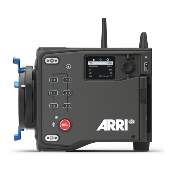
Page 8: Camera Body Overview
LBUS Connector (4-pin LEMO) The LBUS connector is used to connect daisy chainable LBUS devices of the ECS Electronic Control System (lens motors, ARRI Master Grips, ARRI OCU-1) to the camera and supplies regulated 24.0 V with a maximum current of 4.0 A. - Page 9 Right Camera Status LED VF 2 Viewfinder Connector (CoaXPress) VF 2 is the second viewfinder port. The camera uses an industrial CoaXPress interface with an ARRI custom connector to connect the MVF-2 viewfinder with the camera. The interface transmits power,...
- Page 10 2.0 A. PWR (8-pin LEMO) The PWR connector is the main power input for the ALEXA 35 and accepts an input voltage range from 20.5 to 33.6 V DC. You can use power cables KC50-S (K2.75007.0) or KC50-SP-S (K2.0001275) to power the camera from an external source.
- Page 11 Camera Body Overview PWR and BAT Status LEDs The BAT LED indicates the status of the power source connected to the BAT interface on the back of the camera used for onboard batteries, the PWR LED indicates the status of the power source connected to the PWR connector.
- Page 12 Camera Body Overview Camera Top Mounting Points for Accessories Top Connector Fan Outlet WiFi Antenna Connector Mounting Point for Accessories WiFi Antenna Connector Top Connector For future use. WiFi Antenna Connectors (RP-SMA) The camera is equipped with a 2.4 GHz WiFi module and two WiFi antennas, both located on the back of the camera.
- Page 13 The camera saves data such as user setups, frame grabs and log files to USB-C memory sticks formatted with FAT32 or exFAT file systems. Software updates, additional frame lines and ARRI look files are loaded onto the camera from the USB-C memory stick. The USB-C connector (1) can also be...
-
Page 14: Multi Viewfinder Mvf-2 Overview
Multi Viewfinder MVF-2 Overview Multi Viewfinder MVF-2 Overview Flip-out Monitor Diopter Adjustment Proximity Sensor ZOOM Button EXP Button PLAY Button VF 1&2 User Buttons Top Tally Light SET Button User Wheel LOCK Switch REC Button Dove Tail Service Cover Bottom Tally Light Product Label Viewfinder Connector Headphones Out... - Page 15 Multi Viewfinder MVF-2 Overview NOTICE Permanent Activation of the Viewfinder OLED Display Permanent activation can cause irreversible burn-ins on the viewfinder OLED display. Do not cover the viewfinder proximity sensor. When covered, the viewfinder OLED display will be switched on permanently. If you need to cover the viewfinder, disable the viewfinder OLED display first using the EVF Power setting.
- Page 16 K1.0024074 - XXXXX. Viewfinder Connector The ALEXA 35 uses industrial CoaXPress interfaces with a custom ARRI connector to connect the MVF-2 viewfinder with the camera. The interface transmits power, video and control data and supports cable lengths of up to 10 m (33 ft). The VF connector (17) comes without a key, so the VF cables plug in regardless of their orientation and support hot plugging of the viewfinder.
- Page 17 Multi Viewfinder MVF-2 Overview Adjusting the Flip-out Monitor Fold out, swivel and fold in the monitor to put the display visible in the folded-in position. The image on the monitor automatically adjusts its orientation, or can be set to the desired orientation in the camera menu.
-
Page 18: Power Supply
Power Supply Power Supply NOTICE Always keep the PWR connector accessible so that the cable can be unplugged quickly in case of emergency. Unplug the power cable by gripping the power plug, not the cable. Do not use power cables longer than 4m. Operate the system using only the type of power source indicated in the manual. - Page 19 4.0 A. Power Consumption The ALEXA 35 draws between 85 W and 135 W while recording, depending on the set recording resolution and sensor frame rate (with MVF-2 connected, but no further accessories attached). The camera will switch off at 19.5V supply level.
- Page 20 Power Supply ► Select MENU > System > Power > Onboard Battery (BAT) Warning (V) to set the warning threshold (Volts) for the BAT input. Info: When using two B-Mount batteries simultaneously, the BAT warning will not be issued until both batteries have reached the warning threshold.
-
Page 21: Menu Operation
Menu Operation Menu Operation MENU / BACK Button Jogwheel User Wheel HOME / LIVE Button SET Button ► Press the MENU / BACK button (1) on the MVF-2 to access the camera menu. ► Rotate the jogwheel (3) or the user wheel (5) to scroll up or down to select the desired menu entry: Entries with a ">"... - Page 22 Menu Operation FPS (Sensor Frame Rate) The FPS label shows the current sensor frame rate in frames per second. Press the FPS screen button to adjust the sensor frame rate. The FPS label turns orange if the sensor frame rate does not match the project frame rate.
- Page 23 WiFi is active and in client mode. The camera is connected to a network. is not connected to a network. The ARRI ECS White Radio is active and uses WiFi is active and in host mode. the displayed channel number.
-
Page 24: On-Screen Keyboard
Menu Operation On-screen Keyboard When working with textual parameters on the camera, an on-screen keyboard serves to enter text. You need to use the keyboard, for example, to enter the name when saving a user setup. ► Use the jogwheel to select and enter charac- ters. - Page 25 Menu Operation ► Press the SET button (3) to add the new value to the presets list, or the CANCEL button (1) to exit. Info: the SET button will be grayed out and the value displayed in red if the entered value is out of range.
-
Page 26: Side Display
Menu Operation Side Display The camera's side display (1) offers access to main parameters and provides an overview of important settings. The Home Page offers to adjust the main parameters Sensor FPS, Shutter, Exposure Index, ND Filter and White Balance. The Info Page provides an overview about important parameters such as the remaining time of the record- ing medium or the set Look and Texture. -
Page 27: Info Screens
Preparing the folder structure on the USB medium within the camera will not alter existing folders and files on the USB medium. ► Open the media door and insert the USB medium. ► Select MENU > Media > Prepare USB Medium to create the ALEXA 35 folder structure on the USB medium: ARRI/ALEXA35/ FRAMELINES... - Page 28 Menu Operation False Color Info The False Color Info displays a reference chart explaining the color coding used for the False Color exposure tool. PWR/BAT LED Info The PWR/BAT LED Info displays a reference chart explaining the LED states of the PWR and the BAT LEDs.
- Page 29 Menu Operation Export HW Info File HW (HardWare) Info files are required to generate licenses in the ARRI License Shop or may be requested by camera service to get detailed information on the camera's hardware and components revisions. The HW Info file will be exported to the USB medium in the ARRI/ALEXA35/LICENSES folder.
-
Page 30: Status Information And Overlays
Status Information and Overlays Status Information and Overlays The camera displays camera status information on the EVF and the SDI outputs. At the top and bottom of the screen, the camera displays status information in text form. The top status bar displays the current settings of sensor FPS, shutter angle, exposure index, ND filter, and white balance. - Page 31 Status Information and Overlays Status Info Left 13 EVF / SDI 1 / SDI 2 Status Output processing icon. Shows the current processing for the respective output (LogC4 or Look). Exposure tool icon. Indicates that False Color is active on the respective output. Peaking Icon.
- Page 32 Overlays Center marker, marks the center of the image to help in framing. Frame line (here: ARRI 1:2.39) Electronic Horizon overlay. Can be set to display numeric roll and tilt values. 20 The Master Grips / OCU-1 Control overlay indicates which axis is controlled by connected Master Grips and OCU-1.
- Page 33 Status Information and Overlays Enables/disables status overlay of Master Grips / OCU-1 axis control (20). Master Grips / OCU-1 Control Enables/disables the left section of the status info. Info Left Info Right Enables/disables the right section of the status info. Info Top Enables/disables the top section of the status info.
-
Page 34: Main Parameters
Main Parameters Main Parameters Project Settings The project settings menu contains settings that should be configured at the beginning of each project and can be found at MENU > Recording > Project Settings. Project Rate The project rate determines how many frames the timecode counts per second, and also determines the frame rate at which clips are played back. -
Page 35: Sensor Frame Rate
Main Parameters Camera Index Color Set the color of the camera index letter displayed in the Status Info of the SDI outputs (e.g. to match it to the color coding of your cameras). ► Select MENU > Monitoring > SDI > SDI 1 Processing > Overlays > Status Components > Camera Index Letter to display the camera index letter in the SDI 1 Status Info. - Page 36 Main Parameters Shows the effective sensor exposure time. With varying frame rates, it remains identical. Exposure Time Info: Maximum exposure time with a given frame rate is 1/fps, with a limit of 1/1 seconds. When the selected exposure time is no longer possible because you changed the frame rate, the camera uses the longest exposure time possible.
-
Page 37: Exposure Index
Main Parameters Exposure Index The exposure index selects which sensor signal becomes mid gray in the LogC4 image and consequently in the monitor image. Mid gray is encoded as 28% in the LogC4 signal. When the output is set to Rec. 709 and no look file is loaded that modifies the signal, mid gray becomes 40% in the video signal. -
Page 38: Nd Filter
Info Pane visible in the exposure index screen. ND Filter The ALEXA 35 has a built-in motorized and sealed filter stage for Full Spectrum Neutral Density filters (FSND) with densities of 0.6, 1.2 and 1.8 (and an optical clear filter). In comparison to IRND filters, which have an uneven spectral behavior, or to an ordinary ND filter, which opens up at about 675 nm, the FSND filters offer a true, even light attenuation over the whole spectrum. -
Page 39: Timecode
Main Parameters Info: Under- or overexposed images may cause the automatic white balance to fail. Always trigger automatic white balance with properly exposed images. User Button Auto WB supports to quickly execute an auto white balance. Timecode Timecode ensures that each frame of recorded material can be identified with a unique value and synchronized with the appropriate media, such as audio or the second camera in a multicamera application. - Page 40 Main Parameters Regen Based on the timecode run mode, the camera determines the timecode source automatically when set to Regen. If the Run Mode is set to Free Run, the camera regenerates timecode from the timecode connector. The timecode source must be connect- ed to the camera permanently.
- Page 41 Main Parameters Timecode Offset You can apply an offset to LTC input signals to compensate for timecode offsets in external devices. ► Select HOME > TC > Options > TC Offset. ► Adjust the timecode offset in the range of -20 to +20 frames.
-
Page 42: Look Settings
Color Processing and Color Space LogC4 ARRI LogC4 is a direct successor to the prior LogC3 encoding definition in use since 2011 and was designed to optimize the encoding precision and production usability of the increased dynamic range of the ALEXA 35's ALEV4 sensor. -
Page 43: Look File Alf4
10.2 Look File ALF4 The ALEXA 35 uses a new look file (ALF4) which can be created with the ARRI Reference Tool. While the previous ALF-2 look file contained both the creative intent and the conversion to a display color space, the new ALF4 look file is a Log-to-Log file that only contains the creative intent. -
Page 44: Look Intensity
► Insert the USB medium into the camera. ► Select MENU > Image > Look > Look. ► Select a look from the list and press EXPORT. The look file is stored in folder ARRI/ALEXA35/LOOKFILES on the USB medium. 10.4 Look Intensity The Look Intensity adjusts the level of look application to the LogC4 image, where 100% translates to a fully applied look and 0% to a plain LogC4 image. -
Page 45: Arri Textures
ARRIRAW and ProRes. If a texture other than the K445 Default texture is to be used, it is very important for ARRI Textures to be tested during preproduction, in the highest quality viewing environment possible. An ARRI Texture that looks right in a DI suite or on a high end display will be very subtle or perhaps even invisible when viewed in the camera's viewfinder or on the camera's SDI outputs. - Page 46 L345 Shadow texture. Works best for mid to high EI settings. Naming Scheme ARRI Texture names consist of two parts: a technical summary of the texture and a more memorable word or words that describe the texture. While ARRI Textures represent about 30 image processing settings, we have distilled those to four important attributes for the technical summary, so you can quickly tell what to expect.
-
Page 47: Recording
Compact Drives are currently available with 1 TB (960 GB usable) and 2 TB (1920 GB usable) capacity. The 2 TB drive offers about double speed for all ARRIRAW formats on ALEXA 35. There is no advantage other than capacity for the Mini LF. At 24 fps ARRIRAW 4.6K 3:2 Open Gate, the recording time is a little over 25/50 min. - Page 48 Recording The camera records its data to the ARRI UDF file system which is accessible for operating systems without the need for special software. Depending on performance vs budget requirements, you can choose between a USB-C Reader or a Thunderbolt 3 Dock. Mac users who own a SXR Capture Drive Dock can get a Compact Drive Adapter, which combines high performance with lower pricing.
-
Page 49: Recording Codec
ARRIRAW frame. This checksum is recorded as part of the image header and can be used by software like the ARRI Reference Tool, to verify that the ARRIRAW image content has not changed during any copy step. Note that this checksum does not validate the entire file, only the image data. Note that... -
Page 50: Sensor Mode & Recording Resolution
The ideal choice for productions that are shooting for premium image quality, YCbCr are looking for extreme color grading and want to preserve the superior tonal range of ARRI's Log C signal. 13 bit log Use for cinema production, visual effects and high quality TV. It is the best ARRIRAW format for creative color correction, visual effects work and archiving. - Page 51 Recording 4.6K 16:9 Full sensor width recording in a 16:9 format that suits many spherical Super 35 and all large format lenses, with room for flexibility in post. Lower data rate than Open Gate. Active Image Area (Photo sites) Recording Resolutions 4608 x 2592 4.6K (4608 x 2592) Active Image Area (Dimensions)
-
Page 52: Starting Recording
Starting Recording The camera supports various ways to start and stop recording. Recording can be started and stopped The REC button on the camera body, the MVF-2 and ARRI hand units such as the WCU-4 and Hi-5 The Camera Companion App... -
Page 53: Prerecording
Recording Starting recording returns the MVF-2 as well as the side display to their HOME screen and disables access to sensor fps, timecode, shutter, exposure index, auto white balance, erase media, playback and most menu settings. 12.5 Prerecording Prerecording writes images into an internal ring buffer for up to 20 seconds in real time instead of recording them directly to the recording medium. - Page 54 Recording Sensor Mode Recording Resolution Codec Prerec Duration @ 24fps Apple 422 HQ 14.2 s UHD (3840 x 2160) Apple 4444 9.9 s Apple 4444 XQ 6.6 s Apple 422 HQ 2K (2048 x 1152) Apple 4444 20.0 s Apple 4444 XQ Apple 422 HQ HD (1920 x 1080) Apple 4444...
-
Page 55: Clip Naming Scheme
Recording 12.6 Clip Naming Scheme Camera Index The camera index consists of two characters, A-Z + _. User assignable, it should match the camera unit. For example, the camera index A_ can be assigned to the A camera, and B_ to the B camera etc. Reel Counter 4 characters, 0001-9999. -
Page 56: Audio Recording
Recording 12.7 Audio Recording The camera supports to record up to 4 channels of linear PCM audio (24 bit, 48 kHz). Audio Inputs The AUDIO connector (1) is located on the right side of the camera. It is a two channel +24 dBu line level audio input with additional 12 V power output to supply microphone preampli- fiers. - Page 57 Recording Activation of Audio Recording ► Select MENU > Recording > Audio Recording > Audio Recording to enable/disable audio recording. Enabled audio recording is indicated through the audio meters displayed on the HOME screen as well as in the Status Info. The meters show the current level of the channel signal in dBFS. Audio recording is temporarily disabled if the frame rate of the sensor does not match the frame rate of the project.
-
Page 58: Rec Beeper And Tally
Recording to adjust the gain in steps of 1.0 dB for each channel which has either Line In L or Line In R assigned as source. User Buttons Audio Ch1 Increase, Audio Ch1 Decrease, Audio Ch2 Increase, Audio Ch2 Decrease support to quickly adjust gain of channels 1 and 2. User Button Audio Mute int. -
Page 59: Playback
Playback Playback In-camera playback plays back the clips on the recording media at their project frame rate and is output to EVF, Monitor, SDI 1 and SDI 2. Playback can be controlled from a variety of locations such as the MVF-2, the Web Remote, the Camera Companion App or hand units such as the Hi5. - Page 60 Playback Note: Clips may be grayed out if they can not be played back because their recording resolution is not compatible with the currently set recording resolution. Playback Options ► Select PLAY > Options. The Play End Mode defines the behavior when playback reaches the end of a clip and offers the following options: Pause on end Playback pauses at the end of the clip.
-
Page 61: Monitoring
Monitoring Monitoring 14.1 Surround View Surround View displays additional pix- els outside the captured image area (1), allowing the operator to see out- side the captured image and keep un- wanted objects, such as microphone booms, out of the shot. The Surround View area (2) is separated from the captured image area by the Surround Mask (here: 75% Mask). -
Page 62: Magnification
Two screen grabs from an ALEXA 35 in sensor mode 4.6K 3:2 Open Gate with a custom 16:9 4K frame line (red rectangle) ap- plied. The left screen shot shows the SDI 1 output without magnification applied. The right screen grab shows the SDI 1 output with magnification applied to enlarge the image (in this example set to 130%). -
Page 63: Frame Lines
Monitoring Info: Magnification can only be applied on the SDI output(s) with SDI Image set to Processed. Magnification is not available when using 2K or HD Recording Resolutions. Magnification is reset to 100% when Sensor Mode or Recording Resolution is changed. Magnification range is limited when using UHD SDI formats (6G and 12G). - Page 64 Frame Line Display When creating custom frame lines using the ARRI Frame Line & Lens Illumination Tool, you have the possibility to place up to three different frame lines (A, B, C) in one frame line file. However, the camera does not always have to display all three frame lines at the same time, but offers the possibility to configure which frame line(s) are displayed.
-
Page 65: False Color
Monitoring You can configure width, height and offset (position from left and top of image area). ► Select MENU > Monitoring > Frame Lines > User Rectangles > User Rectangles. Following options are available: User Rectangles are not displayed. Rectangle 1 Only user rectangle 1 is displayed. -
Page 66: Peaking
Monitoring Additionally, False Color can be activated in the camera menu: ► Select MENU > Monitoring > SDI > SDI 1 Processing > False Color to activate False Color on the SDI 1 output. ► Select MENU > Monitoring > SDI > SDI 2 Processing > False Color to activate False Color on the SDI 2 output. -
Page 67: Zoom
Monitoring Cyan White Green Magenta Blue Yellow Activation of Peaking User Buttons VF Peaking and SDI 1 Peaking support to quickly enable/disable peaking on the respective output. Active peaking is indicated through the peaking icon displayed in the Status Info of the respective output. 14.6 Zoom The camera supports to zoom into the image e.g. -
Page 68: Sdi Settings
Monitoring Info: SDI Zoom is not available when using UHD SDI formats (6G & 12G). 14.7 SDI Settings SDI Image The setting for the SDI image determines whether the SDI image is output as a clean feed or including status information and status overlays. ►... -
Page 69: Evf And Flip-Out Monitor Settings
Monitoring SDI Frame Rate The SDI frame rate determines the number of images that are output per second on the SDI output(s). It should be set equal to the sensor frame rate. If the frame rate is lower than the sensor frame rate, frame drops will occur. -
Page 70: Return In
Monitoring EVF Eyepiece Heating The MVF-2 viewfinder is equipped with a built-in eyepiece heater to prevent fogging of the eyepiece when shooting in cold environments. The eyepiece heater becomes active when the eyepiece has a temperature of 15° C / 59° F or below. In really cold environments please use the Heated Eyecup HE-7. ►... -
Page 71: 14.10 Sdi Color Bars
Monitoring Activation of Return In Return In can only be switched on and off using a user button assigned with Return In. ► Select MENU > User Buttons and assign Return In to the desired button. ► Press the user button to activate Return In. 14.10 SDI Color Bars The camera supports to output SMPTE color bars on the SDI outputs. -
Page 72: User Buttons
In addition to the user buttons of the camera and the MVF-2, the camera supports to assign functions to the user buttons of electronic accessories such as the hand units HI-5 and WCU-4, ARRI Master Grips, Operator Control Unit OCU-1 and the GPIO box. - Page 73 User Buttons Turns SDI color bars on or off. SDI Color Bars Increases the exposure index to the next value in the list. EI Increase EI Decrease Decreases the exposure index to the next lower value in the list. FPS Increase Sets the sensor frame rate to the next higher value in the list.
-
Page 74: Synchronization
Synchronization Synchronization The camera's sensor and SDI outputs can be synchronized to either a genlock signal (a tri-level HD signal or an analog black burst sig- nal) present at the BNC SYNC IN connector (1) or a timecode signal present at the 5-pin LEMO TC connector (2). The camera's sensor needs to run at equal or double the frame rate of the reference signal to establish synchronization. -
Page 75: Sensor Settings
When shooting ARRIRAW, it is not necessary to load the User Pixel Mask into the camera. Instead, it can be applied to the ARRIRAW files in post production using the ARRI Reference Tool or any third party software that has implemented the User Pixel Mask feature through the ARRI Image SDK. - Page 76 ► Import the ARRIRAW frame grab into the ARRI Reference Tool. ► Use the ARRI Reference Tool to mark defect pixels. The marked pixel coordinates are stored in an XML file called the User Pixel Mask. Please note that it is advisable to mark the least number of pixels necessary, as too many marked pixels can be counter productive.
-
Page 77: System Settings
System Settings System Settings 18.1 Language Setting ► Select MENU > System > Language to set the system language between English and Chinese (simplified). 18.2 System Time and Date ► Select MENU > System > System Time + Date to set the system time and date. 18.3 Button and Display Settings ►... -
Page 78: 18.6.1 Update Of Camera Software
LBUS devices such as cforce mini motors, cforce Plus motors, ARRI Master Grips, ARRI Operator Control Unit OCU-1 and ARRI LCUBE can be updated by the camera. The update requires an update file which can be downloaded from the ARRI website. -
Page 79: 18.6.4 Update Of Codex Compact Drive
System Settings ► Select the LBUS device you want to update and press UPDATE. ► Press CONFIRM to start the update. Cancel with BACK. 18.6.4 Update of Codex Compact Drive The camera supports to update Codex Compact Drives. Updating does not require a dedicated update file. -
Page 80: User Setups
The camera loads the selected user setup and shows a result message. The pop up highlights the parameters that you should check in case certain parameters could not be loaded. Factory Reset You can reset the camera to the ARRI factory default values. ► Select MENU > Setup > Factory Reset. ► Press RESET. - Page 81 User Setups General Groups the general camera configuration and basic project settings. Project Rate Installed Look Files Sensor FPS Presets SDI 1&2 Format Audio (All Settings) Installed Texture Files Shutter Presets SDI 1&2 Frame Rate Timecode (All Settings) Installed Frame Line Files WB Presets SDI 1&2 Image Metadata (All Settings)
-
Page 82: Network
Network Network A network connection can be used to remotely control the camera. The camera's Web Remote, the Camera Companion App or other applications communicating with the camera via the Camera Access Protocol (CAP) can be connected to the camera via Ethernet or WiFi. The Ethernet connector (1) is located on the right side of the camera. - Page 83 The following table gives an overview of suitable channel configurations: ARRI White Radio Channel Number WiFi Channel ZigBee IEEE 802.15.4 Radio Channel Number WiFi Password (Host Mode) The camera uses WPA-2 encryption and requires a password when connecting to it.
-
Page 84: Ethernet Settings
The camera supports to stream real time metadata via Ethernet, to be used in virtual studios (aka volumes with an LED wall, aka mixed reality production systems). For more information please refer to the ARRI Live Link Metadata Manual, available in the White Papers section on the ARRI website. - Page 85 Network Streaming Port ► Select MENU > System > Network / WiFi > Streaming Metadata > Streaming Port to set the destination port between 1024 and 65535. Enable Streaming ► Select MENU > System > Network / WiFi > Streaming Metadata > Enable Streaming to enable metadata streaming.
-
Page 86: Metadata
Metadata Metadata An ARRI camera automatically collects metadata when shooting. This metadata is stored in the header of recorded MXF/Apple ProRes and MXF/ARRIRAW files. The data is also stored in separate Avid Log Exchange ALE files, which keep track of all statics that are recorded on one recording media. -
Page 87: Lens & Electronic Control System (Ecs)
Lens & Electronic Control System (ECS) 22.1 White Radio Configuration The camera has an integrated radio unit via which the ARRI HI-5, WCU-4 and SXU-1 hand held units can be connected to the cam- era. It enables wireless lens control, lens data communication and remote control of basic camera functions. -
Page 88: Lens Motors
For more information about lens motors, please download the lens motor user manuals from the Lens Motors section of the ARRI website. When connecting a cforce plus motor to the camera, please check if the LBUS connector(s) on both motor and lens mount are equipped with a sil- ver washer placed below the red nut (2) of the connector. -
Page 89: Lens Data
The Lens Data System (LDS) allows ARRI cameras and accessories to identify connected lenses and exchange dynamic lens data reflecting the current lens settings. It works with cine lenses using ARRI LDS or LDS-2 technology, lenses using Cooke /i technology and even cine lenses without lens data... - Page 90 These files are available from the Lens Data Archive (LDA), a local library of lens files, which can also be extended by the user. The LDA exists in ARRI cameras or accessories like the UMC-4, RIA-1, or cforce mini RF or in the ECS sync app for iOS.
-
Page 91: Lens Data Archive
Lens & Electronic Control System (ECS) Focus unit is displayed according to the markings on the lens (requires LDS or Cooke /i lens). Lens Default Focus unit is displayed in Feet. Imperial Metric Focus unit is displayed in Meter. 22.4 Lens Data Archive The Lens Data Archive (LDA) is an archive that contains lens tables. -
Page 92: Changing A Lens
Lens & Electronic Control System (ECS) 22.5 Changing a Lens NOTICE Risk of damage and injury when using lenses exceeding the supported entry depth! LPL mount lenses with more than 30.00 mm entry depth and PL mount lenses with more than 38.00 mm entry depth might damage the camera's internal filters. -
Page 93: Ef Lens Iris Adjustment
This option is only available when the camera is equipped with an EF Mount. Furthermore, the iris of EF lenses can be controlled using the ARRI Master Grips or the Operator Control Unit OCU-1. ► Select HOME > EI > Iris. -
Page 94: Enable Lens Mount
Lens & Electronic Control System (ECS) 22.7 Enable Lens Mount You can disable the LDS contacts of the lens mount. Usually this is not necessary, but it can be helpful when e.g. lenses with faulty lens data are used. Please note that as soon as an LDA lens table is activated, the LDS contacts of the lens mount are switched off automatically. -
Page 95: Remote Control
Remote Control Remote Control 23.1 Web Remote The camera can be remotely controlled via WiFi or Ethernet using the camera's Web Remote feature. ► Connect the camera to your computer via WiFi or Ethernet. ► Open a web browser and enter the URL ALEXA35-xxxxx.local (replace xxxxx with the camera's 5- digit serial number). -
Page 96: Camera Access Protocol (Cap)
23.2 Camera Access Protocol (CAP) The Camera Access Protocol (CAP) is an IP based API used to control and monitor ARRI cameras via a network connection. The protocol incorporates functions to perform color grading, query and set values like exposure index or sensor frame rate, start and stop recording and many more. Information on the Camera Access Protocol is available through the ARRI Partner Program free of charge. -
Page 97: Hand Units Hi-5 And Wcu-4
Remote Control 23.4 Hand Units Hi-5 and WCU-4 The ARRI hand units Hi-5 and WCU-4 support to control basic settings of the camera. The following settings can be accessed through the hand units: Rec start/stop White Balance False Color Full Playback Control... -
Page 98: Alexa 35 Accessories
Compatible with ARRI LDS-1 and Cooke /i. The adapter can be mounted either so that the LDS contacts are in the 12:00 position for ARRI lenses, or so that the LDS contacts are in the 3:00 position for Cooke lenses. -
Page 99: 24.1.1 Changing The Lens Mount
(K2.0001107) and the EF Lens Mount (K2.0001103) are mechanically compatible with the ALEXA 35, but these lens mounts are not sufficiently stray light optimized to be used with the ALEXA 35. New lens mounts specifically designed for the ALEXA 35 (PL Mount (LBUS) (K2.0042651), PL Mount (Hirose) (K2.0042652), EF Mount (LBUS) (K2.0019965) ensure that the high dynamic range... - Page 100 ALEXA 35 Accessories NOTICE Dust particles on the sensor cover glass may affect the recorded image! When no lens or lens cap is attached to the camera, dirt and dust particles may enter the camera and settle on the sensor cover glass. Particles on the sensor cover glass can later be visible in the recordings made by the camera.
- Page 101 ALEXA 35 Accessories NOTICE When adjusting the flange focal depth on the LPL mount make sure to insert the shims in the correct orientation. Inserting the shims in the incorrect ori- entation (flipped) may result in a short circuit on the LDS print, compromising LDS functionality (lens de- tection and lens data).
-
Page 102: Mechanical Accessories
35 bottom. Once mounted to the camera, the BUD-1's wide dovetail allows the cam- era to be securely and quickly attached and detached from and to all ALEXA 35 acces- sories that sit below the camera including the CBP-5, CBP-6, BPA-6, CSP-2 and SAM-5 through 9. - Page 103 The Stabilizer Adapter Mount SAM-5 is a sliding dove tail plate with a very small height that connects the ALEXA 35 to a MōVI Pro or M15. The SAM-5 top dove tail slides into the bottom of the Balance Utility Dovetail BUD-1. The SAM-5 bottom is a rail that slides into the top stage of the MōVI Pro or M15.
-
Page 104: 24.2.2 Top Accessories
24.2.2 Top Accessories Low Mode Support LMS-4 K2.0034178 The Low Mode Support LMS-4 is a fully featured top plate for the ALEXA 35. A new quick release mechanism allows the CCH-5 top handle to be easily removed, without tools, while retaining superior rigidity while mounted. Dual rod clamps for optically cen- tered 15 mm rods allow for top mounted motors or traditional viewfinder mounting brack- ets. - Page 105 The Mini Viewfinder Bracket MVB-1 allows the MVF-1 viewfinder to attach to the ALEXA Mini and it allows the MVF-2 viewfinder to attach to the ALEXA 35 or ALEXA Mini LF. This is the traditional viewfinder mounting method found on ALEXA, ALEXA Mini and ALEXA Mini LF cameras.
-
Page 106: 24.2.3 Side Accessories
Camera Side Bracket CSB-1L K2.0033573 The Camera Side Bracket CSB-1L allows mounting of accessories to the left side of the ALEXA 35. It features an ARRI rosette for hand grips and multiple 1/4-20, 3/8-16 and M4 mounting holes. Camera Side Bracket CSB-1R K2.0033571 The Camera Side Bracket CSB-1R allows mounting of accessories to the right side of the ALEXA 35. -
Page 107: 24.2.4 Other Accessories
Plates, Bridge Plate Adapters, Shoulder Pads and the Stabilizer Adapter Mounts. Vertical Top Plate K2.0043666 The Vertical Top Plate attaches to the ALEXA 35's left side and acts as a top plate to support the lightweight Camera Handle LCH-1. Case for ALEXA 35 K2.0040234 The Case for ALEXA 35 support the camera in various rigging configurations and has cut-outs that fits specific support accessories, recording media and media readers. -
Page 108: Electronic Accessories
The Audio Extension Module AEM-1 adds a high-quality audio interface and extra ac- cessory power outputs to the ALEXA 35. Featuring two ultra-low noise microphone pre- amplifier channels, the AEM-1 mounts directly to the rear of the camera as an integrat- ed electronic module. -
Page 109: Battery Adapters
The Battery Adapter Back BAB-LF attaches into the recessed area at the back of the ALEXA 35, the Power Distribution Module PDM-1 or the Audio Extension Module AEM-1 and offers an interface to alternative on-board battery systems originally intended to use... -
Page 111: Appendix
Appendix Appendix 25.1 Data Rates, Recording Times and Max. FPS Rec Time @ 24fps Max. FPS Data Rate @ 24 fps (hh:mm) Sensor Mode Recording Resolution (incl. audio) 1 TB 2 TB 1 TB 2 TB 2.055 GB/h (ARRIRAW) 0:28 00:56 35 fps 75 fps... - Page 112 Appendix Rec Time @ 24fps Max. FPS Data Rate @ 24 fps (hh:mm) Sensor Mode Recording Resolution (incl. audio) 1 TB 2 TB 1 TB 2 TB 324 GB/h (Apple 422 HQ) 2:57 5:55 3.8K 2:1 Ana 2x 482 GB/h (Apple 4444) 1:59 3:59 100 fps...
-
Page 113: Companion Tools
The ARRI Reference Tool (ART) combines the functionality of the ARRIRAW Converter, ARRI Color Tool, and ARRI Meta Extract. It supports all ALEXA 35 recording formats and allows the creation of ALF4 look files, conversion to SDR and HDR color spaces with looks applied, and export to Apple ProRes, OpenEXR and TIFF files. -
Page 114: Connector Pin-Outs
Appendix 25.3 Connector Pin-Outs All pin-outs appear as seen by the user. PWR (LEMO EEJ.2B.308) RS (Fischer DPB102A052-130) Batcom Power GND Power GND Power GND 24 V Aux Batcom GND Batplus Batplus Batplus 12V (LEMO EEG.0B.302.CLN.A365) AUDIO (LEMO EEA.0B.306.CLN) CH 1 (+) CH 1 (-) 12 V Aux CH 2 (+) - Page 115 3 RING 1 GND L Out Audio Cable K2.0023988 ARRI offers an ALEXA Mini LF / ALEXA 35 audio cable with a matching connector to create audio adapters. The following table shows the wire assignments of this cable. Wire Function...
-
Page 116: Dimensional Drawings
Appendix 25.4 Dimensional Drawings ALEXA 35 with LPL Mount (LBUS). All measurements in mm.