Table of Contents
Advertisement
Copyright
This publication, including all photographs, illustrations and software, is protected
under international copyright laws, with all rights reserved. Neither this manual, nor
any of the material contained herein, may be reproduced without written consent of
the author.
Version 1.0
Disclaimer
The information in this document is subject to change without notice. The manufac-
turer makes no representations or warranties with respect to the contents hereof
and specifically disclaims any implied warranties of merchantability or fitness for
any particular purpose. The manufacturer reserves the right to revise this publica-
tion and to make changes from time to time in the content hereof without obligation
of the manufacturer to notify any person of such revision or changes.
Trademark Recognition
Microsoft, MS-DOS and Windows are registered trademarks of Microsoft Corp.
MMX, Pentium, Pentium-II, Pentium-III, Celeron are registered trademarks of Intel
Corporation.
Other product names used in this manual are the properties of their respective owners
and are acknowledged.
Federal Communications Commission (FCC)
This equipment has been tested and found to comply with the limits for a Class B
digital device, pursuant to Part 15 of the FCC Rules. These limits are designed to
provide reasonable protection against harmful interference in a residential instal-
lation. This equipment generates, uses, and can radiate radio frequency energy and,
if not installed and used in accordance with the instructions, may cause harmful
interference to radio communications. However, there is no guarantee that interfer-
ence will not occur in a particular installation. If this equipment does cause harmful
interference to radio or television reception, which can be determined by turning
the equipment off and on, the user is encouraged to try to correct the interference by
one or more of the following measures:
Reorient or relocate the receiving antenna
•
Increase the separation between the equipment and the receiver
•
Connect the equipment onto an outlet on a circuit different from that to
•
which the receiver is connected
•
Consult the dealer or an experienced radio/TV technician for help
Shielded interconnect cables and a shielded AC power cable must be employed with
this equipment to ensure compliance with the pertinent RF emission limits govern-
ing this device. Changes or modifications not expressly approved by the system's
manufacturer could void the user's authority to operate the equipment.
Q77H2-TI USER MANUAL
Preface
Advertisement
Table of Contents

Related Manuals for ECS Q77H2-TI


Summary of Contents for ECS Q77H2-TI
- Page 1 Shielded interconnect cables and a shielded AC power cable must be employed with this equipment to ensure compliance with the pertinent RF emission limits govern- ing this device. Changes or modifications not expressly approved by the system’s manufacturer could void the user’s authority to operate the equipment. Q77H2-TI USER MANUAL...
-
Page 2: Declaration Of Conformity
Provides information on us- page 29 ing the BIOS Setup Utility. Using BIOS Chapter 4 Describes the motherboard page 61 software. Using the Motherboard Software Chapter 5 page 65 Provides basic trouble shoot- Trouble Shooting ing tips. Q77H2-TI USER MANUAL... -
Page 3: Table Of Contents
About the Setup Utility...............29 The Standard Configuration...........29 Entering the Setup Utility............29 Resetting the Default CMOS Values........30 Using BIOS..................30 BIOS Navigation Keys..............31 Main Menu................32 Advanced Menu..............33 Chipset Menu................49 Tweak Menu................52 Boot Menu................57 Security Menu.................58 Exit Menu................59 Updating the BIOS..............60 Q77H2-TI USER MANUAL... - Page 4 Chapter 4 Using the Motherboard Software Auto-installing under Windows XP/7/8........61 ..Running Setup..............61 Manual Installation................63 Chapter 5 Trouble Shooting Start up problems during assembly..........65 Start up problems after prolong use..........66 Maintenance and care tips..............66 Basic Troubleshooting Flowchart...........67 Q77H2-TI USER MANUAL...
-
Page 5: Introducing The Motherboard
Chapter 1 Introducing the Motherboard Introduction Thank you for choosing the Q77H2-TI motherboard. This motherboard is a high performance, enhanced function motherboard designed to support the LGA1155 ® ® ® socket for Intel Generation Core vPro i7/i5 and Core i3/Pentium /Celeron processors for high-end business or personal desktop markets. -
Page 6: Specifications
Rear Panel I/O • 1 x Display port (DP) • 1 x 19V DC_IN port • 1 x RJ45 LAN connector • 4 x USB 3.0 ports • 1 x Audio port (1 x line-out, 1 x Microphone) Q77H2-TI USER MANUAL... - Page 7 - F7 hot key for boot up devices option - Supports PgUp clear CMOS Hotkey (Has PS2 KB Model only) - Supports Multi-Language AP Support • Supports Norton/Cyberlink Form Factor • Thin Mini ITX Size, 170mm x 170mm Q77H2-TI USER MANUAL...
-
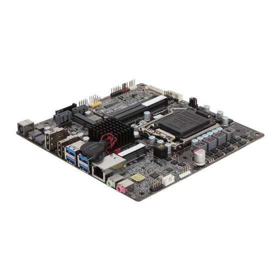
Page 8: Motherboard Components
Motherboard Components Q77H2-TI USER MANUAL... - Page 9 5-pin USB 2.0 header supports one USB 2.0 device 21. LVDS LVDS connector (optional) 22. CIR Consumer infrared header 23. DISP_BRT LVDS brightness control header 24. MON_SW LVDS brightness ON/OFF switch header 25. LCD_SEL LCD panel select header (optional) Q77H2-TI USER MANUAL...
-
Page 10: I/O Ports
No data Activity LED Orange blinking Active No link Link LED Green Link LAN Port 6. Line-out (lime) It is used to connect to speakers or headphones. 7. Microphone (pink) It is used to connect to a microphone. Q77H2-TI USER MANUAL... -
Page 11: Installing The Motherboard
Place the motherboard over the mounting brack- ets and secure the motherboard onto the mounting brackets with screws. Do not over-tighten the screws as this can stress the motherboard. Q77H2-TI USER MANUAL... -
Page 12: Checking Jumper Settings
1. LCD_SEL: LCD panel select header (optional) 1.When your panel connects to LVDS, please check LCD_SEL header setting first. 2.Due to the differences of the panel parameters, please follow the above illustration to place the jumper caps. Q77H2-TI USER MANUAL... - Page 13 The following illustration shows the location of the motherboard jumpers. Pin 1 is labeled. To avoid the system instability after clearing CMOS, we recommend users to enter the main BIOS setting page to “Load Default Settings” and then “Save and Exit Setup”. 3. ME_UNLOCK: ME unlock jumper Q77H2-TI USER MANUAL...
-
Page 14: Installing Hardware
Lift the tail of the load lever and rotate the load plate to fully open position. Grasp the edge of the package substrate. Make sure pin 1 indicator is on your bottom-left side. Aim at the socket and place the package carefully into the socket by purely vertical motion. Q77H2-TI USER MANUAL... - Page 15 Spreader). Engage the load lever while pressing down lightly onto the load plate. Secure the load lever with the hook under retention tab. Then the cover will flick automatically. Please save and replace the cover onto the CPU socket if processor is re- moved. Q77H2-TI USER MANUAL...
-
Page 16: Installing The Cpu Cooler
B. Fasten the cooling fan supporting base onto the CPU socket on the motherboard. And make sure the CPU fan is plugged to the CPU fan connector. C. Connect the CPU cooler power connector to the CPU_FAN connector. Q77H2-TI USER MANUAL... -
Page 17: Installing Memory Modules
Refer to the following to install the memory modules. Install the DIMM module into the slot and press it firmly down until it fits in place. Check that the cutouts on the DIMM module edge connector match the notches in the DIMM slot. Q77H2-TI USER MANUAL... -
Page 18: Installing Add-On Cards
Before installing an add-on card, check the documentation for the card carefully. If the card is not Plug and Play, you may have to manually configure the card before installation. Q77H2-TI USER MANUAL... - Page 19 Make the other end of the cable (with a gold screw) through the upper hole of the bracket, and tighten the antenna on to the gold screw after install- ing a metal gasket on the screw (Please refer to Picture 3). Picture 1 Picture 2 Picture 3 * For reference only Q77H2-TI USER MANUAL...
-
Page 20: Connecting Optional Devices
2-4-5. Connecting Optional Devices Refer to the following for information on connecting the motherboard’s optional devices: Components Components F_USB MON_SW USB_CAM USB_CR DMIC F_AUDIO USB_TP CASE LVDS SATA1~2 DISP_BRT SATA_PWR Q77H2-TI USER MANUAL... - Page 21 A different pin assignment may cause damage or system hang- 2 & 3 & 5. USB_CAM/USB_CR/USB_TP: 5-pin USB 2.0 header supports camera /card reader or other USB 2.0 devices Users please note to install the card to the correct header. Q77H2-TI USER MANUAL...
- Page 22 2.Due to the chipset limitation, using dual displays LVDS(AIO) + VGA or LVDS(AIO) + HDMI will cause the problem that you may not enter BIOS setup or have the display problem. Q77H2-TI USER MANUAL...
- Page 23 7. DISP_BRT: LVDS connector (optional) 8. MON_SW: LVDS brightness ON/OFF switch header Q77H2-TI USER MANUAL...
- Page 24 9. CIR: Consumer infrared header 10. DMIC: Digital microphone header (optional) Q77H2-TI USER MANUAL...
- Page 25 97 Front Panel, please tick off the option of “ Disabled Front Panel Detect ”. If you use HD Audio Front Panel, please don’ t tick off “Disabled Front Panel Detect ” . * For reference only Q77H2-TI USER MANUAL...
- Page 26 SATA1~2 connectors are used to support the Serial ATA 6Gb/s device. Simpler disk drive cabling and easier PC assembly. It eliminates limitations of the current Paral- lel ATA interface. But maintains register compatibility and software compatibility with Parallel ATA. Q77H2-TI USER MANUAL...
- Page 27 14. SATA_PWR: SATA power connector Q77H2-TI USER MANUAL...
-
Page 28: Installing A Hard Disk Drive/Optical Disk Drive
Attach the other end of the combo HDD/ODD cable to the SATA port and SATA_PWR connector on the motherboard. Please note that, connect the black cable to the SATA_PWR connector, and connect the orange cable to the SATA port. * For reference only Q77H2-TI USER MANUAL... - Page 29 Your motherboard features two Mini PCI Express x1 slots, the PCIE2 supports full- card, you can install a Mini SATA (mSATA) card into it. Refer to the illustration below for proper installation: Insert a Mini SATA (mSATA) card into the PCIE2 Slot. Lower the handle and tighten the screws. Q77H2-TI USER MANUAL...
-
Page 30: Connecting Case Components
2-4-7. Connecting Case Components After you have installed the motherboard into a case, you can begin connecting the motherboard components. Refer to the following: Components F_PANEL SYS_FAN CPU_FAN SPKR Q77H2-TI USER MANUAL... - Page 31 50 ms to signal the power supply to switch on or off. The time requirement is due to internal de-bounce circuitry. After receiving a power on/off signal, at least two seconds elapses before the power supply recognizes another on/off signal. Q77H2-TI USER MANUAL...
- Page 32 Users please note that the fan connector supports the CPU cooling fan of 1.1A ~ 2.2A (26.4W max) at +12V. 4. SPKR: 2 Channel audio speaker header (optional) Connect the case speaker cable to SPKR. This concludes Chapter 2. The next chapter covers the BIOS. Q77H2-TI USER MANUAL...
-
Page 33: Using Bios
When you power on the system, BIOS enters the Power-On Self Test (POST) routines. POST is a series of built-in diagnostics performed by the BIOS. After the POST routines are completed, the following message appears: Press DEL to enter SETUP Q77H2-TI USER MANUAL... -
Page 34: Resetting The Default Cmos Values
Some options (marked with a triangle ) lead to submenus that enable you to change the values for the option. Use the cursor arrow keys to scroll through the items in the submenu. Q77H2-TI USER MANUAL... -
Page 35: Bios Navigation Keys
BIOS items presented in this manual. The BIOS setup screens shown in this chapter are for reference only and may differ from the actual BIOS. Please visit the manufacture’s website for updated manual. Q77H2-TI USER MANUAL... -
Page 36: Main Menu
The Date and Time items show the current date and time on the computer. If you are running a Windows OS, these items are automatically updated whenever you make changes to the Windows Date and Time Properties utility. Q77H2-TI USER MANUAL... -
Page 37: Advanced Menu
Trusted Computing F2:Previous Values Intel(R) Rapid Start Technology F3:Optimized Defaults Intel(R) Smart Connect Technology F4:Save & Exit ESC:Exit Version 2.15.1229. Copyright (C) 2012 American Megatrends, Inc. Q77H2-TI USER MANUAL... -
Page 38: Lan Configuration
F3:Optimized Defaults F4:Save & Exit ESC:Exit Version 2.15.1229. Copyright (C) 2012 American Megatrends, Inc. Onboard LAN Controller (Enabled) Use this item to enable or disable Onboard LAN 1 controller. Press <Esc> to return to the Advanced Menu page. Q77H2-TI USER MANUAL... -
Page 39: Pc Health Status
If you choose Manual mode, the fan speed will be adjust depending on users’ parameters. Press <Esc> to return to the PC Health Status page. Q77H2-TI USER MANUAL... - Page 40 System temperature, CPU & DIMM voltage, CPU & System fan speed... etc. • System Temperature • CPU Fan Speed • System Fan Speed • CPU Voltage • AXG Voltage • DIMM Voltage Press <Esc> to return to the Advanced Menu page. Q77H2-TI USER MANUAL...
-
Page 41: Power Management Setup
EUP Function (Enabled) This item allows user to enable or disable EUP support. Power LED Type (Single Color LED) This item shows the type of the power LED. Press <Esc> to return to the Advanced Menu page. Q77H2-TI USER MANUAL... -
Page 42: Acpi Configuration
Version 2.15.1229. Copyright (C) 2012 American Megatrends, Inc. ACPI Sleep State [S3(Suspend to RAM)] This item allows user to enter the ACPI S3 (Suspend to RAM) Sleep State (default). Press <Esc> to return to the Advanced Menu page. Q77H2-TI USER MANUAL... -
Page 43: Cpu Configuration
This item shows that the computer supports Intel VT-x Technology or not. Limit CPUID Maximum (Disabled) Use this item to enable or disable the maximum CPUID value limit, you can enable this item to prevent the system from “rebooting” when trying to install Windows NT 4.0. Q77H2-TI USER MANUAL... - Page 44 Use this item to enable or disable CPU C6 (ACPI C3) report to OS. Enhanced Halt (ClE) (Enabled) Use this item to enable the CPU energy-saving function when the system is not run- ning. Press <Esc> to return to the Advanced Menu page. Q77H2-TI USER MANUAL...
-
Page 45: Sata Configuration
Spin Up Device (Disabled) Use this item to enable or disable the spin up device. External SATA (Disabled) Use this item to enable or disable the external SATA. Press <Esc> to return to the Advanced Menu page. Q77H2-TI USER MANUAL... -
Page 46: Usb Configuration
All USB Devices (Enabled) Use this item to enable or disable all USB devices. Legacy USB Support (Enabled) Use this item to enable or disable support for legacy USB devices. Press <Esc> to return to the Advanced Menu page. Q77H2-TI USER MANUAL... -
Page 47: Amt Configuration
If enabled, this requires additional firmware in the SPI device. MEBx Setting Screen (Disabled) Use this item to enable or disable Intel ME BIOS Extension setting screen. Press <Esc> to return to the Advanced Menu page. Q77H2-TI USER MANUAL... -
Page 48: Intel Txt Configuration
Secure Mode Extensions (Enabled) Use this item to enable or disable secure mode extension. Intel TXT(LT) Configuration (Disabled) Use this item to enable or disable Intel Intel(R) TXT(LT) support. Press <Esc> to return to the Advanced Menu page. Q77H2-TI USER MANUAL... -
Page 49: Super Io Configuration
This item allows you to enable or disable serial port. Device Settings (IO=3F8h; IRQ=4) This item shows the information of the device settings. Change Settings (Auto) Use this item to change device settings. Press <Esc> to return to the Super IO Configuration page. Q77H2-TI USER MANUAL... -
Page 50: Trusted Computing
F3:Optimized Defaults F4:Save & Exit ESC:Exit Version 2.15.1229. Copyright (C) 2012 American Megatrends, Inc. TPM Support (Enabled) Use this item to enable or disable the TPM support. O.S will not show TPM. Reset of platform is required. Q77H2-TI USER MANUAL... -
Page 51: Intel Rapid Start Technology
F4:Save & Exit ESC:Exit Version 2.15.1229. Copyright (C) 2012 American Megatrends, Inc. Intel(R) Rapid Start Technology (Disabled) Use this item to enable or disable Intel(R) Rapid Start Technology. Press <Esc> to return to the Advanced Menu page. Q77H2-TI USER MANUAL... -
Page 52: Intel Smart Connect Technology
F2:Previous Values F3:Optimized Defaults F4:Save & Exit ESC:Exit Version 2.15.1229. Copyright (C) 2012 American Megatrends, Inc. ISCT Configuration (Disabled) Use this item to enable or disable ISCT configuration. Press <Esc> to return to the Advanced Menu page. Q77H2-TI USER MANUAL... -
Page 53: Chipset Menu
VT-d Capability (Supported) This item shows that the computer supports VT-d capability or not. VT-d (Enabled) Use this item to check to enable VT-d function on MCH. Press <Esc> to return to the Chipset Menu page. Q77H2-TI USER MANUAL... -
Page 54: Pch Configuration
This item enables or disables the warning if the case is opened up, and the item below indicates the current status of the case. Chassis Opened (No) This item indicates whether the case has been opened. Press <Esc> to return to the Chipset Menu page. Q77H2-TI USER MANUAL... - Page 55 F1:General Help F2:Previous Values F3:Optimized Defaults F4:Save & Exit ESC:Exit Version 2.15.1229. Copyright (C) 2012 American Megatrends, Inc. ME FW Version (8.1.0.1265) This item shows the ME FW version. Press <Esc> to return to the Chipset Menu page. Q77H2-TI USER MANUAL...
-
Page 56: Tweak Menu
This item shows the information of CPU frequency. CPU Ratio (20) This item allows users to control non turbo CPU ratio. Enhanced Intel SpeedStep Technology (Enabled) This item allows users to enable or disable the EIST (Enhanced Intel SpeedStep Tech- nology). Q77H2-TI USER MANUAL... - Page 57 Use this item to control iGFX Core Current Limit. Long Duration Maintained (28) Use this item to control the time window over PL1 value should be maintained. This is for Turbo mode. Press <Esc> to return to the Tweak Menu page. Q77H2-TI USER MANUAL...
- Page 58 Active to Active Delay(tRRD) (4) This item controls the active bank x to active bank y in memory clock cycles. Read CAS# Precharge(tRTP) (4) This item controls the Read to precharge delay for memory devices, in memory clock cycles. Q77H2-TI USER MANUAL...
- Page 59 Graphics Core Ratio Limit (20) This item allows you to control the internal GFX Turbo ratio. Graphics Voltage(1/256) (0) This item allows you to adjust the internal GFX voltage. Press <Esc> to return to the Tweak Menu page. Q77H2-TI USER MANUAL...
- Page 60 2. Press and hold the “Page Up Key (PgUp)” of the keyboard, and then boot the PC 3. Two seconds after the PC boots up, release the “Page Up Key (PgUp)”. 4. The BIOS returns to the default setting by itself. Q77H2-TI USER MANUAL...
-
Page 61: Boot Menu
Use this item to select boot mode. Set Boot Priority This item enables you to set boot priority for all boot devices. Boot Option #1 /2 /3 /4 /5 /6 /7 These items show the boot priorities. Q77H2-TI USER MANUAL... -
Page 62: Security Menu
Secure Boot state (Disabled) This item allows you to enable or disable the secure boot state. Secure Boot (Disabled) This item is used to control the secure boot flow, it is possible only if system runs in User Mode. Q77H2-TI USER MANUAL... -
Page 63: Exit Menu
This item enables you to save the changes that you have made as user defaults. Restore User Defaults This item enables you to restore the user defaults. Boot Override Use this item to select the boot device. Q77H2-TI USER MANUAL... -
Page 64: Updating The Bios
BIOS jumper, reset the jumper to protect the newly installed BIOS from being overwritten. The computer will restart automatically. This concludes Chapter 3. Refer to the next chapter for information on the software supplied with the motherboard. Q77H2-TI USER MANUAL... -
Page 65: Using The Motherboard Software
Click Setup. The installation program begins: The following screens are examples only. The screens and driver lists will be different according to the motherboard you are installing. The motherboard identification is located in the upper left-hand corner. Q77H2-TI USER MANUAL... - Page 66 Windows 8 will show the following screen after system restart, you must select “Desktop” in the bottom left to install the next driver. Q77H2-TI USER MANUAL...
-
Page 67: Manual Installation
If the driver you want to install does not have a setup program, browse to the oper- ating system subfolder and locate the readme text file (README.TXT or README.DOC) for information on installing the driver or software for your operating system. Q77H2-TI USER MANUAL... - Page 68 Memo Q77H2-TI USER MANUAL...
-
Page 69: Trouble Shooting
CPU heatsink. Check if the CPU fan is working properly while the system is running. 2. From the BIOS setting, try to disable the Smartfan function to let the fan run at default speed. Doing a Load Optimised Default will also disable the Smartfan. Q77H2-TI USER MANUAL... -
Page 70: Start Up Problems After Prolong Use
6. If possible, ensure the power cord has an earth ground pin directly from the wall outlet. This will reduce voltage fluctuation that may damage sensitive devices. Q77H2-TI USER MANUAL... - Page 72 Memo Q77H2-TI USER MANUAL...