Table of Contents
Advertisement
1
Chapter 1
Introducing the Motherboard
Introduction
Thank you for choosing the H11H4-I motherboard. This motherboard is a high
performance, enhanced function motherboard designed to support Intel Skylake
processors for high-end business or personal desktop markets.
This motherboard is based on integrated Intel Chipset for best desktop platform
solution. Skylake is a dual-core processor. The chipset for Skylake is highly inte-
grated and high performance. Moreover, Skylake will feature DirectX11.1-compli-
ant GCN-based graphics and support Win8 and UEFI Secure Boot. This motherboard
supports up to 16 GB 260pin SO-DIMM memory with
dual-channel DDR4 2133
(1GB/ 2GB/ 4GB/ 8GB)
SDRAM. One PCI Express x16 slot is supported, is fully
compliant to the PCI Express Base Specification revision 2.0. One Mini PCIE is also
supported. It implements an EHCI (Enhanced Host Controller Interface) compliant
interface that provides four USB 2.0 ports (two USB 2.0 headers support additional
four USB 2.0 ports and one port is supported by mPCIE 2.0 USB signal) and four USB
3.0 ports at the rear panel.
The motherboard is equipped with advanced full set of I/O ports in the rear panel,
including PS/2 mouse and PS/2 keyboard connectors, two Serial ports (COM), one
VGA port, two Lan ports, four USB 3.0 ports, one HDMI port and audio jacks for
line-out and Mic-in.
In addition, this motherboard supports two SATA 6.0Gb/s connectors.
Introducing the Motherboard
Advertisement
Table of Contents

Related Manuals for ECS H11H4-I


Summary of Contents for ECS H11H4-I
-
Page 1: Chapter 1 Introducing The Motherboard
Chapter 1 Introducing the Motherboard Introduction Thank you for choosing the H11H4-I motherboard. This motherboard is a high performance, enhanced function motherboard designed to support Intel Skylake processors for high-end business or personal desktop markets. This motherboard is based on integrated Intel Chipset for best desktop platform solution. - Page 2 Feature Processor The motherboard uses Skylake CPU that carries the following features: • DirectX11.1-compliant GCN-based graphics architecture • Supports “Hyper-Threading” technology APU • Supports Win7/ Win8.1/ Win10 and UEFI Secure Boot. “Hyper-Threading” technology enables the operating system into thinking it’s hooked up to two processors, allowing two threads to be run in parallel, both on separate “logical”...
-
Page 3: Ethernet Lan
Ethernet LAN The onboard LAN provides the following features: • Supports PCI Express • IEEE 802.3/z • Wake-on-LAN (including from S3, S4, S5, power button off) and remote wake-up support • PXE and RPL support Expansion Options The motherboard comes with the following expansion options: •... -
Page 4: Specifications
Specifications • Intel Skylake series processors, up to 4 cores • Supports “Hyper-Threading” technology APU Chipset • Integrated Intel Skylake H110 chip Memory • Dual-channel DDR4 memory architecture • 2 DDR4 260pin SO-DIMM sockets support up to 16 GB • Supports 2133 (1GB/ 2GB/ /4GB/ 8GB) SDRAM Expansion •... - Page 5 • AMI BIOS with 64Mb SPI Flash ROM System BIOS • Supports Plug and Play, S1 / STR (S3) / STD (S4) , Hard- ware monitor • Supports ACPI & DMI • Audio, LAN, can be disabled in BIOS • Supports Dual Display •...
-
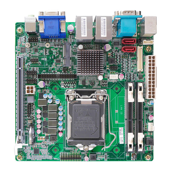
Page 6: Motherboard Components
Motherboard Components Introducing the Motherboard... - Page 7 Table of Motherboard Components LABEL COMPONENTS 1. CPU Socket LGA1151 socket for Intel Skylake processors 2. LPT Printer header 3. COM3~6 Onboard serial port headers 4. ATX_12V 4-pin +12V power in connector 5. F_PANEL Front panel switch/LED header 6. CLR_CMOS Clear CMOS button with jumper 7.
- Page 8 Memo Introducing the Motherboard...
-
Page 9: Chapter 2 Installing The Motherboard
Chapter 2 Installing the Motherboard Safety Precautions • Follow these safety precautions when installing the motherboard • Wear a grounding strap attached to a grounded device to avoid dam- age from static electricity • Discharge static electricity by touching the metal case of a safely grounded object before working on the motherboard •... -
Page 10: Checking Jumper Settings
Do not over-tighten the screws as this can stress the motherboard. Checking Jumper Settings This section explains how to set jumpers for correct configuration of the motherboard. Setting Jumpers Use the motherboard jumpers to set system configuration options. Jumpers with more than one pin are numbered. -
Page 11: Setting (Default)
Checking Jumper Settings The following illustration shows the location of the motherboard jumpers. Pin 1 is labeled. Jumper Settings Type Jumper Description Setting (default) Press the button to clear CMOS CLR_CMOS Button Clear CMOS Before clearing the CMOS, make sure to turn off the system. -
Page 12: Installing Hardware
Installing Hardware Installing Memory Modules This motherboard accommodates two memory modules. It can support DDR4 2133 (1GB/ 2GB/ 4GB/ 8GB). The total memory capacity is 16 GB. Do not remove any memory module from its antistatic packaging until you are ready to install it on the motherboard. Handle the modules only by their edges. -
Page 13: Installation Procedure
Installation Procedure Refer to the following to install the memory modules. This motherboard supports unbuffered DDR4 SDRAM . Push the latches on each side of the DIMM slot down. Align the memory module with the slot. The DIMM slots are keyed with notches and the DIMMs are keyed with cutouts so that they can only be installed correctly. -
Page 14: Expansion Slots
Expansion Slots Installing Add-on Cards The slots on this motherboard are designed to hold expansion cards and connect them to the system bus. Expansion slots are a means of adding or enhancing the motherboard’s features and capabilities. With these efficient facilities, you can in- crease the motherboard’s capabilities by adding hardware that performs tasks that are not part of the basic system. - Page 15 Follow these instructions to install an add-on card: Remove a blanking plate from the system case corresponding to the slot you are going to use. Install the edge connector of the add-on card into the expansion slot. Ensure that the edge connector is correctly seated in the slot. Secure the metal bracket of the card to the system case with a screw.
-
Page 16: Connecting Optional Devices
Connecting Optional Devices Refer to the following for information on connecting the motherboard’s optional devices: F_AUDIO: Front Panel Audio Header The front panel audio header allows the user to install auxiliary front-oriented microphone and line-out ports for easier access. This header supports HD audio by default. - Page 17 COM3~6 : Onboard serial port header Connect a serial port extension bracket to this header to add a second serial port to your system. Signal Name Signal Name C3_DCD C5_DCD C3_DSR C5_DSR C3_RXD C5_RXD C3_RTS C5_RTS C3_TXD C5_TXD C3_CTS C5_CTS C3_DTR C5_DTR C3_RI...
- Page 18 SATA1~2: Serial ATA 6.0Gb/s connector This connector is used to support the Serial ATA devices for the highest data transfer rates (6.0 Gb/s), simpler disk drive cabling and easier PC assembly. Signal Name Signal Name Ground Ground Ground No pin CASE: Opened Chassis detective header This detects if the chassis cover has been removed.
- Page 19 F_USB1~2: Front Panel USB 2.0 Headers The motherboard has two USB 2.0 headers supporting four USB 2.0 ports. Additionally, some computer cases have USB ports at the front of the case. If you have this kind of case, use auxiliary USB connector to connect the front-mounted ports to the motherboard.
- Page 20 LVDS: LVDS Connector Signal Name Signal Name VDDSAFE LVDS_L2_P VDDSAFE LVDS_U2_P VDDSAFE LVDS_CLKL_N VDDSAFE LVDS_CLKU_N LVDS_L0_N LVDS_CLKL_P LVDS_U0_N LVDS_CLKU_P LVDS_L0_P LVDS_U0_P LVDS_CH7511_DDC_CLK LVDS_CH7511_DDC_DATA LVDS_L1_N LVDS_U1_N LVDS_L1_P LVDS_L3_N LVDS_U1_P LVDS_U3_N LVDS_L3_P LVDS_U3_P LVDS_L2_N Back Light En LVDS_U2_N VCON Installing the Motherboard...
-
Page 21: Installing A Sata Hard Drive
Installing a SATA Hard Drive This section describes how to install a SATA Hard Drive. About SATA Connectors Your motherboard features two SATA connectors supporting a total of two drives. SATA refers to Serial ATA (Advanced Technology Attachment) is the standard inter- face for the IDE hard drives which are currently used in most PCs. -
Page 22: Connecting I/O Devices
Connecting I/O Devices The backplane of the motherboard has the following I/O ports: PS2 Mouse Use the upper PS/2 port to connect a PS/2 pointing device. PS2 Keyboard Use the lower PS/2 port to connect a PS/2 keyboard. Serial port (COM) Use the COM port to connect the serial devices such as mice or fax/modems. -
Page 23: Connecting Case Components
Connecting Case Components After you have installed the motherboard into a case, you can begin connecting the motherboard components. Refer to the following: Connect the system cooling fan connector to SYS_FAN. Connect the CPU cooling fan connector to CPU_FAN. Connect the case switches and indicator LEDs to the F_PANEL. Connect the case speaker cable to SPKR. - Page 24 Connecting 4-pin power in cable The ATX_12V power in connector is used to provide power to the CPU. When installing 4-pin power cable, the latches of power cable and the ATX12V match perfectly. 4-pin power cable SYS_FAN: System Cooling FAN Power Connector Signal Name Function System Ground...
- Page 25 ATX_POWER: Standard ATX 24-pin Power Connector Signal Name Signal Name +3.3V +3.3V +3.3V -12V PS_ON PWRGD +5VSB +12V +12V +3.3V Installing the Motherboard...
-
Page 26: Hard Drive Activity Led
Front Panel Header The front panel header (F_PANEL) provides a standard set of switch and LED headers commonly found on ATX or Micro ATX cases. Refer to the table below for information: Signal Signal Hard disk LED (+) Power Switch (+) MSG LED (+) Reset Switch (+) Hard disk LED (-)