
Related Manuals for B&B Electronics EIR405-SFP-T


Summary of Contents for B&B Electronics EIR405-SFP-T
- Page 1 Manual Documentation Number EIR405-SFP-T-0109m www.bb-elec.com www.bb-europe.com...
- Page 2 All Brand names used in this manual are the registered trademarks of their respective owners. The use of trademarks or other designations in this publication is for reference purposes only and does not constitute an endorsement by the trademark holder Manual Documentation Number EIR405-SFP-T-0109m www.bb-elec.com...
-
Page 3: Table Of Contents
Wiring the Power Inputs ..........................4 Wiring the Fault Alarm Contact ........................5 LED Indicators..............................6 Ports................................6 Cabling .................................7 Mounting Installation ..........................12 DIN-Rail Mounting ............................12 Wall Mount Plate Mounting ........................14 Hardware Installation..........................15 Installation Steps ............................16 Trouble shooting............................17 Technical Specification ..........................18 Manual Documentation Number EIR405-SFP-T-0109m www.bb-elec.com www.bb-europe.com... -
Page 4: Overview
Fault LED will light. The contacts for the alarm output will also open. Flexible Mounting The EIR405-SFP-T can be DIN or Panel mounted. The compact design is suitable for space-constrained environments such as a small cabinet. Manual Document Number EIR-SFP-T-0109m www.bb-elec.com... -
Page 5: Features
Overview Advanced Protection The power line input on the EIR405-SFP-T supports up to 3,000 VDC EFT protection, which secures the equipment against unregulated voltages and makes the system safer and more reliable. The Ethernet ports support up to 4,000 VDC ESD protections which makes the switch suitable for harsh environments. -
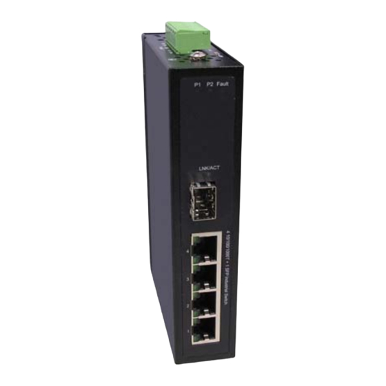
Page 6: Hardware Description
Hardware Description Hardware Description Front Panel The Front Panel of the EIR405-SFP-T is shown below. Manual Documentation Number EIR-SFP-T-0109M www.bb-elec.com www.bb-europe.com... -
Page 7: Top View
Hardware Installation Top View The top panel view of the EIR405-SFP-T is equipped with one terminal block connector that consists of two 12 to 48 VDC power inputs and the fault alarm output. Wiring the Power Inputs Follow the steps below to insert the power wires. -
Page 8: Wiring The Fault Alarm Contact
Hardware Installation Wiring the Fault Alarm Contact The fault alarm contact is in the middle of terminal block connector as shown below. If one of the power sources fails a fault will be detected causing the circuit to open. Insert the wires into the fault alarm contact (No. 3 & 4) Note The wire gauge for the terminal block should be 12 to 24 AWG. -
Page 9: Led Indicators
Hardware Installation LED Indicators Below is a table that explains the status of each the power and network status LED’s found on the front panel of the EIR405-SFP-T. Color Description Power input 1 is active Green Power input 1 is inactive... -
Page 10: Cabling
Hardware Installation All copper ports on the EIR405-SFP-T support automatic MDI/MDI-X operation, you can use straight-through cables (See Figure below) for all network connections to PCs or servers, or to other switches or hubs. In straight-through cables, pins 1, 2, 3, and 6, at one end of the cable, are connected straight through to pins 1, 2, 3 and 6 at the other end of the cable. - Page 11 Hardware Installation The small form-factor pluggable (SFP) is a compact optical transceiver. Manual Document Number EIR-SFP-T-0109m www.bb-elec.com www.bb-europe.com...
- Page 12 Hardware Installation To connect the transceiver and fiber cable, follow the steps below. (Note: modules typically terminate with an LC fiber connector) First, insert the SFP transceiver into the SFP module cage. Notice that the triangle mark is at the bottom of the module. Transceiver Inserted Manual Document Number EIR-SFP-T-0109m www.bb-elec.com...
- Page 13 Hardware Installation Second, insert the fiber cable into the transceiver. LC fiber cable shown installed into the transceiver Removing the LC fiber cable and SFP transceiver, follow the steps below: First, press the upper side of the LC connector down and pull it out before releasing. Remove LC connector Manual Document Number EIR-SFP-T-0109m www.bb-elec.com...
- Page 14 Hardware Installation Second, swivel the metal latch away from the switch and pull the transceiver out. Pull out the SFP module Manual Document Number EIR-SFP-T-0109m www.bb-elec.com www.bb-europe.com...
-
Page 15: Mounting Installation
Hardware Installation Mounting Installation DIN-Rail Mounting The DIN rail clip comes screwed on to the switch, from the factory. If the DIN rail clip is not screwed on the switch, please see the following figure to re-attach the DIN-Rail clip. Then follow the steps below to hang the switch onto a DIN rail. - Page 16 Hardware Installation First, insert the top of DIN rail clip onto the piece DIN rail track. Then, lightly push the bottom of the switch so it can snap the rest of the way onto the DIN rail track. Check that the switch is held tightly to the DIN rail track. Manual Document Number EIR-SFP-T-0109m www.bb-elec.com www.bb-europe.com...
-
Page 17: Wall Mount Plate Mounting
Hardware Installation To remove the switch from the track, reverse the steps above. • First pushing down lightly on the switch will give enough room for the bottom of the switch to clear the bottom of the DIN rail track. •... -
Page 18: Hardware Installation
Hardware Installation Hardware Installation The diagram below shows a typical switch installation for the EIR405-SFP-T. Manual Documentation Number EIR-SFP-T-0109M www.bb-elec.com www.bb-europe.com... -
Page 19: Installation Steps
Hardware Installation Installation Steps Unpack the switch. Check that the DIN rail clip is screwed onto the switch. If the DIN rail clip is not screwed onto the switch, please refer to DIN-Rail Mounting section for DIN-Rail installation. If you want to wall or panel mount the switch, then please refer to Wall or Panel Mount Plate Mounting section for wall place installation. -
Page 20: Trouble Shooting
Trouble shooting Trouble shooting • Verify that you are using a power supply ranging from 12 to 48VDC. Applying more than 48VDC could cause damage to the switch. • Be sure the proper cable is used in your network. Refer to the Cabling section of this manual for help. -
Page 21: Technical Specification
Technical Specifications Technical Specification Communications Compatibility IEEE 802.3, 802.3u, 802.3ab IEEE 802.3x, 802.3z 10/100/1000Base-T, 1000Base-FX Up to 1000 Mbps Transmission Speed Interface Connectors 4 x RJ-45 (4-port 10/100/1000TX) 1 x SFP port (mini-GBIC port) 6-pin removable screw terminal (power input & fault relay output) LED Indicators Unit: P1, P2, Fault Ethernet port: Link/Active, 1000M... - Page 22 Technical Specifications Protection ESD (Ethernet) 4,000 VDC Surge (EFT for power) 3,000 VDC Reverse Power Overload current protection Environment Operating Temperature -40 to 75 C (-40 to 167 Operating Humidity 5% to 95% (non-condensing) Storage Temperature -40 to 85 C (-40 to 185 Certifications Safety UL, cUL, CE EN60950-1...