Table of Contents
Advertisement
Quick Links
Download this manual
See also:
Instruction Manual
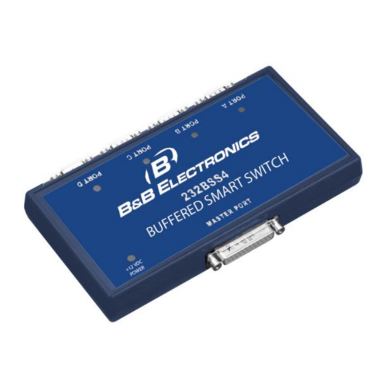
Buffered Smart Switch
Model 232BSS4
Documentation Number: 232BSS4-2907
This product designed and manufactured in Ottawa, Illinois USA
of domestic and imported parts by
707 Dayton Road -- P.O. Box 1040 -- Ottawa, IL 61350 USA
Phone (815) 433-5100 -- General Fax (815) 433-5105
Phone (815) 433-5100 -- General Fax (815) 433-5105
Website:
www.bb-elec.com
Sales e-mail:
orders@bb-elec.com
-- Fax (815) 433-5109
Technical Support e-mail:
support@bb.elec.com
-- Fax (815) 433-5104
European Headquarters
B&B Electronics
Westlink Commercial Park -- Oranmore, Co. Galway, Ireland
Phone +353 91-792444 -- Fax +353 91-792445
Website:
www.bb-europe.com
Sales e-mail:
sales@bb-europe.com
Technical Support e-mail:
support@bb-europe.com
B&B Electronics Mfg. Co. Inc. -- July 2007
Manual Documentation Number: 232BSS4-2907
B&B Electronics Mfg Co Inc – 707 Dayton Rd - PO Box 1040 - Ottawa IL 61350 - Ph 815-433-5100 - Fax 815-433-5104 – www.bb-elec.com
B&B Electronics – Westlink Commercial Park – Oranmore, Galway, Ireland – Ph +353 91-792444 – Fax +353 91-792445 – www.bb-europe.com
Advertisement
Table of Contents

Related Manuals for B&B Electronics 232BSS4


Summary of Contents for B&B Electronics 232BSS4
- Page 1 B&B Electronics Mfg. Co. Inc. -- July 2007 Manual Documentation Number: 232BSS4-2907 B&B Electronics Mfg Co Inc – 707 Dayton Rd - PO Box 1040 - Ottawa IL 61350 - Ph 815-433-5100 - Fax 815-433-5104 – www.bb-elec.com B&B Electronics – Westlink Commercial Park – Oranmore, Galway, Ireland – Ph +353 91-792444 – Fax +353 91-792445 – www.bb-europe.com...
- Page 2 This document contains information that is proprietary and confidential to B&B Electronics Mfg. Co. Inc. The methods described herein are for the exclusive use of B&B Electronics authorized personnel. Any unauthorized use or dissemination of the information contained in the document is strictly forbidden. B&B Electronics Mfg Co Inc –...
-
Page 3: Table Of Contents
APPENDIX C: BLOCK DIAGRAM............1 APPENDIX D: DECLARATION OF CONFORMITY......1 Manual Documentation Number: 232BSS4-2907 Table of Contents B&B Electronics Mfg Co Inc – 707 Dayton Rd - PO Box 1040 - Ottawa IL 61350 - Ph 815-433-5100 - Fax 815-433-5104 – www.bb-elec.com... - Page 4 Documentation Number 232BSS4-2907m B&B Electronics Mfg Co Inc – 707 Dayton Rd - PO Box 1040 - Ottawa IL 61350 - Ph 815-433-5100 - Fax 815-433-5104 – www.bb-elec.com B&B Electronics – Westlink Commercial Park – Oranmore, Galway, Ireland – Ph +353 91-792444 – Fax +353 91-792445 – www.bb-europe.com...
-
Page 5: Chapter 1 - Introduction
Two units can also be used back-to-back to provide automatic connection between devices over a single data channel. LEDs on the 232BSS4 indicate when the unit is powered up and which port is selected to send data to the Master port. -
Page 6: Specifications
Windows 95/98/NT/2000/XP/Vista Supplied Accessories: CDROM with Setup Program Instruction Manual Default Parameters When shipped, the 232BSS4 comes set up for the following parameters: Auto Select mode OFF DTR NOT required to accept commands THREE character command Char1 = ESC (Decimal 27) Char2 = STX (Decimal 2) Char3 = “0”... -
Page 7: Checklist
Examine the shipping carton and contents for physical damage. If damage is found, file a claim with the shipper immediately. The following equipment should be in the shipping carton: 1. RS-232 Buffered Smart Switch model 232BSS4 2. Instruction Manual 3. (2) 3.5" floppy disks If any of the items above are not in the shipping carton contact the shipper immediately. - Page 8 Documentation Number 232BSS4-2907m B&B Electronics Mfg Co Inc – 707 Dayton Rd - PO Box 1040 - Ottawa IL 61350 - Ph 815-433-5100 - Fax 815-433-5104 – www.bb-elec.com B&B Electronics – Westlink Commercial Park – Oranmore, Galway, Ireland – Ph +353 91-792444 – Fax +353 91-792445 – www.bb-europe.com...
-
Page 9: Chapter 2: Operation
LED Indicators The 232BSS4 has five LED indicators. The first, labeled “+12 VDC POWER” indicates that power is applied to the switch. The other four, labeled “PORT A” to “PORT D” indicate which Slave port is currently selected to transmit to the Master. -
Page 10: Onfigurations
On the Master port, pin four (RTS) would have to be held high by the host device in order for the 232BSS4 to send data. On the Slaves, pin eight (CTS) needs to be held high by the Slave device for the 232BSS4 to send data. -
Page 11: Smart Switch
Thus the command sequence would look like: {Char1}{Char2}{Char3}{Command Character} Char1-3 would be defined by the user through the setup software. Char3 would only be sent if the 232BSS4 was set up for a four character command. Documentation Number 232BSS4-2907m &B Electronics Mfg Co Inc – 707 Dayton Rd - PO Box 1040 - Ottawa IL 61350 - Ph 815-433-5100 - Fax 815-433-5104 – www.bb-elec.com... -
Page 12: Xplanation
Four Character Command Format: Char1 Char2 Char3 Command Char Control Char Control Char is only needed for Tx Only, Clear Buffer, and Ignore Commands Table 2.1 - 232BSS4 Command Summary Function Command Control Comments Char. Char. Select Port A Tx & Rx “A”... - Page 13 The Slave port that is sending to the Master is not affected. The lowest four bits of the control byte tell the 232BSS4 which ports should receive the following data. Bit 0 represents port A, Bit 1 represents port B, Bit 2 represents port C, and Bit 3 represents port D.
- Page 14 Slave port buffers before it is sent to the Master. The lowest four bits of the control byte tell the 232BSS4 which ports’ buffers to purge. Bit 0 represents port A, Bit 1 represents port B, Bit 2 represents port C, and Bit 3 represents port D.
- Page 15 15 or 79 “O” Note: The 232BSS4 ignores the upper 4 bits of the control byte. If the Master device is incapable of sending characters outside the printable ASCII range, decimal 64 can be added to each of the control bytes and the switch will operate properly.
- Page 16 Note that these procedures are not needed if the binary file will be transferred from the Slave devices to the Master device. No switching commands are used in the 232BSS4 with data from this direction, so no inadvertent switching can occur.
- Page 17 Method2 – Ignore Commands Using DTR The second method of ignoring command sequences is to set the 232BSS4 to ignore commands if DTR is low from the Master device. This option is enabled through the setup software. This method is useful if the length of the binary file transfers are not known.
-
Page 18: Auto Select
Auto Select mode. The Port Time and Inactivity Time tell the 232BSS4 how much time to spend on each port, and how long a port must be inactive before switching to the next port. - Page 19 When the specified Port Time has elapsed, the 232BSS4 checks in sequence for other Slave ports with buffered data and switches to them. If no other Slave ports need access to the Master, the current Slave port will again be connected until another Port Time has elapsed.
-
Page 20: Using The Back Tob
To configure the 232BSS4 as a four port splitter/combiner: • Set up the ports on the 232BSS4 to match the data format of the connected devices. If the Slave devices stream data, the Master port should be set to a higher baud rate than the slaves. - Page 21 For details on how to use the setup software, see Chapter 4. Note that in Back to Back operation the 232BSS4 Master ports will normally be connected to either the Master port of another switch or some type of modem.
- Page 22 If you have more than four devices that are sending data, more than one 232BSS4 can be cascaded, allowing more ports to be added. The 232BSS4 buffers data from all ports at once, making it well suited for devices that will send a fixed amount of data at sporadic intervals, such as measurement instruments, security access card readers, barcode scanners, or time clocks.
- Page 23 PC should be written to recognize this preamble as an address or identifier of the data source. Documentation Number 232BSS4-2907m &B Electronics Mfg Co Inc – 707 Dayton Rd - PO Box 1040 - Ottawa IL 61350 - Ph 815-433-5100 - Fax 815-433-5104 – www.bb-elec.com...
- Page 24 Documentation Number 232BSS4-2907m B&B Electronics Mfg Co Inc – 707 Dayton Rd - PO Box 1040 - Ottawa IL 61350 - Ph 815-433-5100 - Fax 815-433-5104 – www.bb-elec.com...
-
Page 25: Chapter 3: Port Connections
Chapter 3: PORT CONNECTIONS DTE/DCE Explanation In order to determine the proper port connections to the 232BSS4, it is necessary to have a basic understanding of the terms DTE and DCE. RS- 232 was designed, using DB-25 connectors, for connecting a DTE (Data Terminal Equipment) device to a DCE (Data Communication Equipment) device. - Page 26 DCE, a null modem adapter such as B&B’s model 232DTE is needed. If the user chooses to use the DTR signal to tell the 232BSS4 when to accept commands, the DTR output from the Master device should be connected to pin 20.
-
Page 27: Chapter 4: Setup Software
Connection A serial (COM) port of the computer should be connected to the Master port of the 232BSS4. If the computer’s serial port is a 25 pin D-sub, a straight through connection cable is required. If the computer’s serial port is a 9-pin D-sub, the cable should be an XT to AT adapter cable such as B&B’s model 232CAM, or a cable that would normally be used with a... -
Page 28: Nstallation
Software Installation The setup software for the 232BSS4 must be installed on your hard drive before it can be run. All directions assume the CDROM drive is assigned to drive D. If your drive is assigned another drive name, replace that name for D in the instructions. -
Page 29: Utorial
Step 4: If you are creating a configuration without a switch connected, proceed to “Single Unit Main screen.” Otherwise, select the way that the 232BSS4 will be used. If the 232BSS4 is going to be used with an intelligent Master device, or if only certain parameters are going to change, select Single Unit operation. - Page 30 Read Module Configuration: This button will read the configuration from the connected 232BSS4. The 232BSS4 is read upon entering the Main Screen, so it should not have to be read again unless it is necessary to set the parameters back after changing.
- Page 31 Be sure to review all changes before saving using the View Module Configuration button. Run Self Test: The 232BSS4 is programmed with a Self Test mode. The microprocessor checks the UARTs, RAM, and EEPROM and reports any errors back to the setup software. If the software reports an error, contact B&B Technical Support.
- Page 32 #2 tab is selected. The user should not have to reload the configuration except when the parameters need to be reset to those already saved in the switch. The load configuration button will load the configuration from the connected switch and assume these apply to the selected Unit. View Module Configuration: Each unit’s configuration can be reviewed on one screen by selecting the appropriate tab and clicking the View Module Configuration...
- Page 33 Copying Parameters Between Switches: The 232BSS4 setup software can save configuration data to a file for copying of parameters. Any unit’s setup can be copied by first reading the data from one switch, then saving to another. Step 1: Run the setup software.
- Page 34 Documentation Number 232BSS42907 Manual B&B Electronics Mfg Co Inc – 707 Dayton Rd - PO Box 1040 - Ottawa IL 61350 - Ph 815-433-5100 - Fax 815-433-5104 B&B Electronics Ltd – Westlink Commercial Park – Oranmore, Galway, Ireland – Ph +353 91-792444 – Fax +353 91-792445...
-
Page 35: Appendix A: Ascii Character Codes
Appendix A: ASCII Character Codes DECIMAL to HEX to ASCII CONVERSION TABLE DEC HEX ASCII KEY DEC HEX ASCII DEC HEX ASCII DEC HEX ASCII ctrl @ ctrl A ctrl B “ ctrl C ctrl D ctrl E ctrl F &... - Page 36 Appendix A Documentation Number 232BSS42907 Manual B&B Electronics Mfg Co Inc – 707 Dayton Rd - PO Box 1040 - Ottawa IL 61350 - Ph 815-433-5100 - Fax 815-433-5104 B&B Electronics Ltd – Westlink Commercial Park – Oranmore, Galway, Ireland – Ph +353 91-792444 – Fax +353 91-792445...
-
Page 37: Appendix B: Cable Charts
(DSR) * <---------> (GND) <----------- (DCD) * -----------> (DTR) * * - Pins 6, 8, & 20 looped back internally on the 232BSS4 Chart B.2. DTE (PC) DB9 Connector to Master Port DTE (PC) 232BSS4 Serial Port Signal Master Port (DCE) - Page 38 (RTS) <----------- (CTS) * - Pins 6, 8, & 20 looped back internally on the 232BSS4 Appendix B: Cable Charts Documentation Number 232BSS42907 Manual B&B Electronics Mfg Co Inc – 707 Dayton Rd - PO Box 1040 - Ottawa IL 61350 - Ph 815-433-5100 - Fax 815-433-5104...
-
Page 39: Dce (Modem ) Db25 C
Chart B.3. DCE (Modem) DB25 Connector to Master Port DCE (Modem) 232BSS4 Serial Port Signal Master Port (DCE) DB25 Connector Direction DB25 Connector <----------- (RD) -----------> (TD) <----------- (CTS) -----------> (RTS) -----------> (DTR) * <---------> (GND) <----------- (DSR) * • - Pins 6, 8, & 20 looped back internally on the 232BSS4 Chart B.4. - Page 40 • - Pins 6, 8, & 20 looped back internally on the 232BSS4 Slave Port Connections: Chart B.5. Ports A - D (DTE) to DTE (PC) DB25 Connector 232BSS4 DTE (PC) Ports A - D (DTE) Signal Serial Port DB9 Connector...
- Page 41 ----------> 8 (CTS) <---------- * - Pins 1, 4, & 6 looped back internally on the 232BSS4 Documentation Number 232BSS42907 Manual Appendix B: Cable Charts B&B Electronics Mfg Co Inc – 707 Dayton Rd - PO Box 1040 - Ottawa IL 61350 - Ph 815-433-5100 - Fax 815-433-5104...
- Page 42 Appendix B: Cable Charts Documentation Number 232BSS42907 Manual B&B Electronics Mfg Co Inc – 707 Dayton Rd - PO Box 1040 - Ottawa IL 61350 - Ph 815-433-5100 - Fax 815-433-5104 B&B Electronics Ltd – Westlink Commercial Park – Oranmore, Galway, Ireland – Ph +353 91-792444 – Fax +353 91-792445...
-
Page 43: Appendix C: Block Diagram
Appendix C: Block Diagram 232BSS4 Block Diagram Documentation Number 232BSS42907 Manual Appendix C B&B Electronics Mfg Co Inc – 707 Dayton Rd - PO Box 1040 - Ottawa IL 61350 - Ph 815-433-5100 - Fax 815-433-5104 B&B Electronics Ltd – Westlink Commercial Park – Oranmore, Galway, Ireland – Ph +353 91-792444 – Fax +353 91-792445... - Page 44 Appendix C Documentation Number 232BSS42907 Manual B&B Electronics Mfg Co Inc – 707 Dayton Rd - PO Box 1040 - Ottawa IL 61350 - Ph 815-433-5100 - Fax 815-433-5104 B&B Electronics Ltd – Westlink Commercial Park – Oranmore, Galway, Ireland – Ph +353 91-792444 – Fax +353 91-792445...
-
Page 45: Appendix D: Declaration Of Conformity
DECLARATION OF CONFORMITY Manufacturer’s Name: B&B Electronics Manufacturing Company Manufacturer’s Address: P.O. Box 1040 707 Dayton Road Ottawa, IL 61350 USA Model Numbers: 232BSS4 Description: RS-232 4-Port Buffered Smart Switch Type: Light industrial ITE equipment Application of Council Directive: 89/336/EEC Standards:...