Sony Handycam DCR-PC1 Service Manual
Digital video camera recorder
Hide thumbs
Also See for Handycam DCR-PC1:
- Operating instructions manual (103 pages) ,
- Service manual (64 pages) ,
- Limited warranty (1 page)
Table of Contents
Advertisement
SERVICE MANUAL
Ver 1.0 1998. 07
D200 MECHANISM
DCR-PC1: NTSC model
DCR-PC1E: PAL model
MICROFILM
DCR-PC1/PC1E
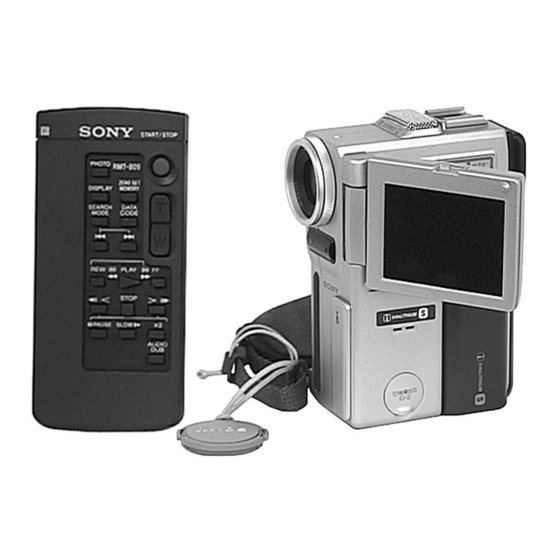
Photo: DCR-PC1E
RMT-809
For MECHANISM ADJUSTMENTS, refer to the "DV MEHCANICAL
ADJUSTMENT MANUAL
supplement: 9-973-815-81) and "DV MECHANICAL ADJUSTMENT
MANUAL
D200 MECHANISM " (original: 9-973-981-11).
SPECIFICATIONS
DIGITAL VIDEO CAMERA RECORDER
RMT-808/809
US Model
Canadian Model
AEP Model
UK Model
Australian Model
Chinese Model
Hong Kong Model
Tourist Model
D MECHANISM " (original: 9-973-815-11,
— Continued on next page —
DCR-PC1
DCR-PC1E
E Model
DCR-PC1/PC1E
Advertisement
Table of Contents

Related Manuals for Sony Handycam DCR-PC1


Summary of Contents for Sony Handycam DCR-PC1
- Page 1 DCR-PC1/PC1E RMT-808/809 SERVICE MANUAL US Model Canadian Model DCR-PC1 AEP Model Ver 1.0 1998. 07 UK Model Australian Model Chinese Model DCR-PC1E E Model Hong Kong Model Tourist Model Photo: DCR-PC1E D200 MECHANISM RMT-809 DCR-PC1/PC1E DCR-PC1: NTSC model For MECHANISM ADJUSTMENTS, refer to the “DV MEHCANICAL DCR-PC1E: PAL model ADJUSTMENT MANUAL D MECHANISM ”...
- Page 2 MARK ! ON THE SCHEMATIC DIAGRAMS AND IN THE PARTS CRITIQUES POUR LA SÉCURITÉ DE FONCTIONNEMENT. NE LIST ARE CRITICAL TO SAFE OPERATION. REPLACE THESE REMPLACER CES COMPOSANTS QUE PAR DES PIÈSES SONY COMPONENTS WITH SONY PARTS WHOSE PART NUMBERS DONT LES NUMÉROS SONT DONNÉS DANS CE MANUEL OU APPEAR AS SHOWN IN THIS MANUAL OR IN SUPPLEMENTS DANS LES SUPPÉMENTS PUBLIÉS PAR SONY.
-
Page 3: Table Of Contents
TABLE OF CONTENTS SERVICE NOTE Trouble check ······································································ 1-26 Self-diagnosis function ························································ 1-27 Power Supply During Repairs ············································ 5 Identifying the parts ····························································· 1-28 How to Take a Cassette Out When the Main Power Warning indicators ······························································· 1-30 Cannot Be Turned on ·························································· 5 DISASSEMBLY SELF-DIAGNOSIS FUNCTION 2-1. - Page 4 • DD-111 (DC/DC Converter) D Page Table ·································································· 5-32 Printed Wiring Board ···································· 4-72 3-3. System Control System Adjustment ······························ 5-34 • DD-111 (DC/DC Converter) Battery End Adjustment (VC-210 board) ······················ 5-34 Schematic Diagram ······································· 4-75 3-4. Servo and RF System Adjustment ································· 5-35 Cap FG Duty Adjustment (MR-40 board) ·····················...
-
Page 5: Service Note
SERVICE NOTE POWER SUPPLY DURING REPAIRS In this unit, about 10 seconds after power is supplied (4.2V) to the battery terminal using the regulated power supply, the power is shut off so that the unit cannot operate. This following two methods are available to prevent this. Take note of which to use during repairs. -
Page 6: Self-Diagnosis Function
SELF-DIAGNOSIS FUNCTION SELF-DIAGNOSIS FUNCTION SELF-DIAGNOSIS DISPLAY When problems occur while the unit is operating, the counter of the When problems occur while the unit is operating, the self-diagnosis function starts working, and displays on the viewfinder or LCD viewfinder shows a 4-digit display consisting of an alphabet and screen what to do. -
Page 7: Self-Diagnosis Code Table
SELF-DIAGNOSIS CODE TABLE Self-diagnosis Code Block Detailed Symptom/State Correction Function Code Condensation. Remove the cassette, and insert it again after one hour. Video head is dirty. Clean with the optional cleaning cassette. Non-standard battery is used. Use the info LITHIUM battery. LOAD direction. -
Page 8: General
DCR-PC1/PC1E SECTION 1 This section is extracted from instruction manual GENERAL of DCR-PC1E (3-864-275-51). - Page 17 1-10...
- Page 18 1-11...
- Page 19 1-12...
- Page 20 1-13...
- Page 21 1-14...
- Page 22 1-15...
- Page 23 1-16...
- Page 24 1-17...
- Page 25 1-18...
- Page 26 1-19...
- Page 27 1-20...
- Page 28 1-21...
- Page 29 1-22...
- Page 30 1-23...
- Page 31 1-24...
- Page 32 1-25...
- Page 33 1-26...
- Page 34 1-27...
- Page 35 1-28...
- Page 36 1-29...
- Page 37 1-30E...
-
Page 38: Disassembly
DCR-PC1/PC1E SECTION 2 DISASSEMBLY The following flow chart shows the disassembly procedure. DCR-PC1 2-1. CABINET (L) ASSEMBLY, CABINET (R) ASSEMBLY 1 - @¡ PD-102 board 1 - 6 MD block assembly 2-2. 2-5. 7 , 8 EVF assembly 9 - !£ Microrophone unit 1 - 6 , @™... -
Page 39: Cabinet (L) Assembly, Evf, Md Block Assembly
2-2. CABINET (L) ASSEMBLY, EVF, MD BLOCK ASSEMBLY !™ Microphone unit !£ Microphone case assembly !¡ Microphone GEL sheet 2 Screw (0-No. +P2 M1.7) !º Microphone retainer plate 9 Pan head small screw 7 Move in the direction of (0-No. special M2 × 4) the arrow a . -
Page 40: Control Switch Block
2-4. CONTROL SWITCH BLOCK Be sure to disengage the catch. Slant here in the direction of the arrow a and remove it in the direction of the arrow b . 2 Remove an end of the grip belt. Be sure to disengage the catch. !º... -
Page 41: Cabinet (R) Assembly, Pd-102 Board
2-5. CABINET (R) ASSEMBLY, PD-102 BOARD Cabinet (R) assembly @£ LCD hinge assembly #• LCD lock pin @™ Two screws #ª LCD lock retainer (M1.7) $º LCD lock #¶ Push the area $¡ Compres- @¢ Remove the shown by the sion coil claw with arrow. -
Page 42: Board
2-6. CD-203 BOARD !º CCD fitting adapter CCD block assembly 4 Two screws 6 CD-203 board 3 Connector (0-No. +P2 B1.7) (CD-203 board CN450) 7 CD frame 2 Peel lens flexible sheet off. 5 Two screws (0-No. +P3 B1.7) VF lens assembly (Refer to sec. 2-7.) 9 Filter block 8 Sealing rubber !¡... -
Page 43: Service Position (Mainly For Adjustment)
2-8. SERVICE POSITION (Mainly for adjustment) Firstly: Remove the cabinet (R) referring to section 2-1. Then connect the CPC-6 jig, the adjustment remote commander and the AC adapter as shown below. CPC-6 terminal board jig Adjustment remote commander (J-6082-371-A) (RM-95) CPC-6 flexible jig (J-6082-370-A) AC adapter (4.2 Vdc) -
Page 44: Circuit Boards Location
2-10.CIRCUIT BOARDS LOCATION VF-125 CD-203 (BACK-LIGHT DRIVE) (CCD IMAGER) PD-102 PR-31 RGB DRIVER, (PANEL REVERSE) TIMING GENERATOR VC-210 CAMERA PROCESS, MECHA SP CONTROL, BLOCKING, CAMERA HI CONTROL, AUDIO PROCESSOR, EVF DRIVER, DC/DC CONVERTER, LINE OUT AMP TB-37 (BATTERY TERMINAL) DD-111 MR-40 (DC/DC CONVERTER) DRUM/CAPSTAN DRIVE,... -
Page 45: Flexible Boards Location
2-11.FLEXIBLE BOARDS LOCATION CONTROL SWITCH BLOCK (FK-4780) CONTROL SWITCH BLOCK (ME-4780) FP-586 (From LOADING MOTOR) (From VIDEO HEAD) (From DRUM MOTOR) FP-585 (MODE) (From CAPSTAN MOTOR) 2-8E... -
Page 46: Block Diagrams
DCR-PC1/PC1E SECTION 3 BLOCK DIAGRAMS 3-1. OVERALL BLOCK DIAGRAM... -
Page 47: Power Block Diagram
DCR-PC1/PC1E 3-2. POWER BLOCK DIAGRAM 3-8E... -
Page 48: Printed Wiring Boards And Schematic Diagrams
DCR-PC1/PC1E DCR-PC1/PC1E SECTION 4 PRINTED WIRING BOARDS AND SCHEMATIC DIAGRAMS 4-1. FRAME SCHEMATIC DIAGRAM FRAME SCHEMATIC DIAGRAM... -
Page 49: Printed Wiring Boards And Schematic Diagrams
DCR-PC1/PC1E 4-2. PRINTED WIRING BOARDS AND SCHEMATIC DIAGRAMS CD-203 (CCD IMAGER) PRINTED WIRING BOARD — Ref. No. CD-203 Board; 4,000 Series — CD-203 BOARD THIS NOTE IS COMMON FOR WIRING BOARDS AND SCHEMATIC DIAGRAMS (In addition to this, the necessary note is printed in each block) C450 CN451 D-9 C451... - Page 50 DCR-PC1/PC1E DCR-PC1/PC1E CD-203 BOARD CAMERA REC IC450 1,2 6.5Vp-p IC450 3,4 6.6Vp-p IC450 !¡,!™ 16.33MHz 3Vp-p Q450 E 0.96Vp-p CCD IMAGER 4-10 CD-203...
- Page 51 DCR-PC1/PC1E DCR-PC1/PC1E VC-210 BOARD (SIDE A) VC-210 (CAMERA PROCESS, MECHA SP CONTROL, BLOCKING, CAMERA HI CONTROL, AUDIO PROCESSOR, EVF DRIVER, DC/DC CONVERTER, LINE OUT AMP) PRINTED WIRING BOARD — Ref. No. VC-210 Board; 10,000 Series — C202 C2054 C-12 D2203 D-8 Q2216 D-8 R1622 C-5 R2247 E-7...
- Page 52 DCR-PC1/PC1E DCR-PC1/PC1E VC-210 BOARD (SIDE B) C231 E-10 C2058 A-10 R238 E-11 C232 E-10 C2059 C-10 R245 E-11 C233 E-11 C2060 B-11 R246 F-10 C234 E-11 C2061 C-10 R247 E-11 C235 D-10 C2062 B-11 R250 E-11 C236 D-10 C2063 B-11 R252 E-10 C239...
- Page 53 DCR-PC1/PC1E For schematic diagram • Refer to page 4-13 for printed wiring board. VC-210 BOARD (1/8) CAMERA REC IC203 @§,@¶ R2.5/P0 R1.9/P0 0.96Vp-p R1.8/P0 –0.5 R2.5/P0 IC203 2-!¡ 2.6Vp-p 56nsec IC202 5 CAMERA REC/PB 3.2Vp-p 36.0MHz IC202 !™ CAMERA REC/PB 18.0MHz 3.2Vp-p IC206 $º...
- Page 54 DCR-PC1/PC1E DCR-PC1/PC1E For schematic diagram • Refer to page 4-13 for printed wiring board. VC-210 BOARD (2/8) CAMERA REC/PB IC2401 1 (X2400) 2.2Vp-p 20.0MHz MECHA SP CONTROL 4-23 4-24 4-25 VC-210 (2/8)
- Page 55 DCR-PC1/PC1E For schematic diagram • Refer to page 4-14 for printed wiring board. VC-210 BOARD (3/8) CAMERA REC/PB Q1500 E 0.22Vp-p Q1501 E 0.2Vp-p !£ Q1502 E 0.26Vp-p !º Q1503 E 0.32Vp-p !¡ Q1504 E 0.4Vp-p !™ IC1502 8 3.5Vp-p 13.5MHz !º...
- Page 56 DCR-PC1/PC1E For schematic diagram • Refer to page 4-14 for printed wiring board. PR-31 (PANEL SW) PRINTED WIRING BOARD VF-125 CD-203 (BACK-LIGHT DRIVE) (CCD IMAGER) R0.4/P2.7 PD-102 PR-31 RGB DRIVER, (PANEL REVERSE) TIMING GENERATOR !∞ !¢ VC-210 BOARD (4/8) CAMERA REC/PB !¢...
- Page 57 DCR-PC1/PC1E DCR-PC1/PC1E For schematic diagram • Refer to page 4-14 for printed wiring board. AUDIO PROCESSOR 4-37 4-38 VC-210 (5/8)
-
Page 58: Evf Driver
DCR-PC1/PC1E For schematic diagram • Refer to page 4-14 for printed wiring board. VC-210 BOARD (6/8) CAMERA REC/PB !§ @™ IC5000 8 IC5002 $¡ 0.26Vp-p 2.8Vp-p 16.1MHz !¶ @£ IC5000 9 IC5002 !• @¡ @º 0.2Vp-p @¢ 17.0msec 2.7Vp-p !ª @§... -
Page 59: Dc/Dc Converter
DCR-PC1/PC1E DCR-PC1/PC1E For schematic diagram • Refer to page 4-14 for printed wiring board. 15.6 12.2 14.9 14.9 12.2 15.6 12.3 14.9 14.9 -0.2 -6.6 -7.1 -7.1 -7.8 -6.6 DC/DC CONVERTER 4-43 4-44 VC-210 (7/8) -
Page 60: Line Out Amp
DCR-PC1/PC1E For schematic diagram • Refer to page 4-14 for printed wiring board. VC-210 BOARD (8/8) CAMERA REC/PB @¶ IC1402 @∞ 0.4Vp-p @• IC1402 @ª 0.32Vp-p @¶ #¡ @ª IC1402 7 @• #º 2.2Vp-p @ª #º IC1402 !™ 1.4Vp-p #¡ IC1402 !§... -
Page 61: Drum/Capstan Drive, Rec/Pb Head Amp
DCR-PC1/PC1E MR-40 (DRUM/CAPSTAN DRIVE, REC/PB HEAD AMP) PRINTED WIRING BOARD — Ref. No. MR-40 Board; 10,000 Series — MR-40 BOARD C1804 C2583 R1943 A-8 C1805 C2585 R1944 A-8 C1806 C2586 R1945 B-8 C1807 C2587 R1946 A-7 C1809 C2588 R1947 D-8 C1833 C2589 R1949 B-8... -
Page 62: Drum/Capstan Drive
DCR-PC1/PC1E MR-40 BOARD (1/2) CAMERA REC/PB IC2503 4 IC2503 ^º 2.6Vp-p 2.6Vp-p 6.7msec 1.1msec 900kHz IC2503 @™,@£,@¢ IC2503 ^£ !º 0.23Vp-p 0.1Vp-p 1.1msec 1.1msec 900kHz IC2503 @∞,@§,@¶ IC2504 !¶ 2.3Vp-p 2.6Vp-p 1.1msec 0.92msec !º IC2503 $∞ IC2504 #¡,#£,#¢ 0.6Vp-p 2.7Vp-p 80msec 0.56sec R2.6/P1.3... -
Page 63: Rec/Pb Head Amp
DCR-PC1/PC1E For schematic diagram • Refer to page 4-49 for printed wiring board. MR-40 BOARD (2/2) !™ IC1900 !¡ CAMERA REC 2.2Vp-p 25nsec !™ !£ IC1816 1267 CAMERA REC 3.5Vp-p !¢ 6.8msec !¢ IC1816 @¶ PB !£ 0.35Vp-p 6.8msec REC/PB HEAD AMP 4-54 4-55 4-56... -
Page 64: Rgb Driver
DCR-PC1/PC1E DCR-PC1/PC1E For schematic diagram • Refer to page 4-63 for printed wiring board. PD-102 BOARD (1/2) CAMERA REC/PB IC8001 8 0.26Vp-p IC8001 9 0.2Vp-p IC8001 !º 0.22Vp-p IC8001 @º 7Vp-p IC8001 @™ 7Vp-p IC8001 @¢ 7Vp-p IC8001 #¶ 3Vp-p 5.507MHz RGB DRIVER 4-57... -
Page 65: Timing Generator
DCR-PC1/PC1E DCR-PC1/PC1E PD-102 BOARD (2/2) IC8201 #¢ CAMERA REC/PB 3.0Vp-p 15.9kHz TIMING GENERATOR 4-61 4-62 PD-102 (2/2) -
Page 66: Rgb Driver, Taming Generator) Printed Wiring Board
DCR-PC1/PC1E PD-102 (RGB DRIVER, TIMING GENERATOR) PRINTED WIRING BOARD — Ref. No. PD-102 Board; 10,000 Series — PD-102 BOARD C8001 D8200 B-1 R8020 D-2 C8002 D8201 C-2 R8021 D-3 C8003 IC8000 C-1 R8022 D-3 C8004 IC8001 D-2 R8023 D-3 C8005 IC8200 B-3 R8024 D-2 C8006... -
Page 67: Back-Light Driver
DCR-PC1/PC1E VF-125 (BACK-LIGHT DRIVER) PRINTED WIRING BOARD — Ref. No. VF-125 Board; 10,000 Series — VF-125 BOARD C5500 C5501 C5502 CN5500 B-6 CN5501 A-1 CN5502 C-1 Q5500 D-1 Q5501 D-1 Q5502 A-1 Q5503 A-1 Q5504 A-1 Q5505 A-2 Q5506 A-1 Q5507 A-1 R5500 D-1 R5501 D-1... - Page 68 DCR-PC1/PC1E DCR-PC1/PC1E BACK-LIGHT DRIVER CONTROL SWITCH BLOCK 4-67 4-68 4-69 VF-125 FK-4780...
- Page 69 DCR-PC1/PC1E TB-37 (BATTERY TERMINAL) PRINTED WIRING BOARD DD-111 (DC/DC CONVERTER) PRINTED WIRING BOARD — Ref. No. DD-111 Board; 10,000 Series — DD-111 BOARD C3201 D3210 C-9 R3222 C-5 C3202 D3212 C-9 R3223 D-5 C3203 D3213 B-10 R3224 B-7 C3204 D3215 C-9 R3225 B-6 C3206 D3221 B-7...
- Page 70 DCR-PC1/PC1E DD-111 BOARD CAMERA REC/PB LANC IC3200 1 (REMOTE) 5Vp-p 2.5msec IC3200 ^¢ (PLUG IN POWER) 4.2Vp-p 2.5msec S-1 VIDEO VIDEO/AUDIO OUT (HEADPHONES) DC/DC CONVERTER 4-75 4-76 4-77 4-78E DD-111...
-
Page 71: Adjustments
DCR-PC1/PC1E SECTION 5 ADJUSTMENTS 5-1. CAMERA SECTION ADJUSTMENT When performing adjustments, refer to the layout diagrams for adjustment related parts beginning from page 5-46. NTSC model : DCR-PC1 PAL model : DCR-PC1E 1-1. PREPARATIONS BEFORE ADJUSTMENT (CAMERA SECTION) 1-1-1. List of Service Tools •... -
Page 72: Preparations
1-1-2. Preparations Note 1: For details of how remove the cabinet and boards, refer to “2. DISASSEMBLY”. Pattern box Note 2: When performing only the adjustments, the lens block and boards need not be disassembled. Note 3: As the power supply of this machine, use the AC adapter that is unique to this machine. - Page 73 Must be connected when using the MENU button To PR-31 board Must be connected when using the LCD display To PD-102 board CN8000 Adjustment CPC-6 terminal board jig remote commander (J-6082-371-A) Cabinet (R) Must be connected when performing the view finder system adjustments.
-
Page 74: Precaution
1-1-3. Precaution 1. Setting the Switch Unless otherwise specified, set the switches as follows and perform adjustments without loading cassette. POWER switch (FK4780) ........CAMERA FOCUS (FK4780) ..........MANUAL DEMO MODE (Menu display) ........OFF DIGITAL EFFECT (ME4780) ......... OFF DIGITAL ZOOM (Menu display) ........ -
Page 75: Initialization Of F, E Page Data
1-2. INITIALIZATION OF F, E PAGE DATA 1. Initializing the F, E Page Data 3. F Page Table Note: If the F, E page data has been initialized, the following adjustments Note: Fixed data-1 : Initialized data ( Refer to “1. Initializing the F, E need to be performed again. - Page 76 Initial value Initial value Address Remark Address Remark NTSC NTSC PAL Fixed data-2 Fixed data-1 Angular velocity sensor sensitivity adj. (Initialized data) Optical axis adj. Color reproduction adj. Fixed data-1 (Initialized data) Hall adj. Fixed data-1 (Initialized data)
- Page 77 Initial value Initial value Address Remark Address Remark NTSC PAL NTSC PAL Fixed data-1 Fixed data-1 (Initialized data) (Initialized data) Table. 5-1-1...
- Page 78 4. E Page table Initial value Address Remark Note: Fixed data-1 : Initialized data ( Refer to “1. Initializing the F, E NTSC Page Data”.) Fixed data-1 Fixed data-2 : Modified data (Refer to “2. Modification of F, E Page Data”).
-
Page 79: Camera System Adjustments
1-3. CAMERA SYSTEM ADJUSTMENTS Before perform the camera system adjustments, check that the specified value of “Base Band Block Adjustment” of “VIDEO SYSTEM ADJUSTMENT” are satisfied. 1. 36 MHz Origin Oscillation Adjustment 2. HALL Adjustment (VC-210 board) For detecting the position of the lens iris, adjust the HALL amplifier Set the frequency of the clock for synchronization. -
Page 80: Flange Back Adjustment
3. Flange Back Adjustment The inner focus lens flange back adjustment is carried out automatically. In whichever case, the focus will be deviated during auto focusing/manual focusing. 3-1. Flange Back Adjustment (1) 3-2. Flange Back Adjustment (2) Perform this adjustment after performing “Flange Back Adjustment Subject Flange back adjustment chart (1)”. -
Page 81: Flange Back Check
4. Flange Back Check Subject Siemens star (2.0 m from the front of the lens) (Luminance: approx. 230 lux) Measurement Point Check operation on monitor TV Measuring Instrument (Note) Specified Value Focused at the TELE end and WIDE end. Note: When the auto focus is ON, the lens can be checked if it is focused or not by observing the data on the page A of the adjustment remote commander. -
Page 82: Optical Axis Adjustment
5. Optical Axis Adjustment Align the lens optical axis with the that of the CCD imager. If deviated, center of picture can lose focus when zoom is operated from the WIDE end to the TELE end. Subject Siemens star Measurement Point Check on monitor TV Measuring Instrument Adjusting Page... -
Page 83: Picture Frame Setting
6. Picture Frame Setting 7. AGC Gain Calibration Adjustment Subject Color bar chart standard picture frame Subject Clear chart (Color bar chart standard (1.5 m from the front of the lens) picture frame) Measurement Point Video output terminal Measurement Point DDS display of LCD or monitor TV Measuring Instrument Oscilloscope and monitor TV... -
Page 84: Color Reproduction Adjustment
8. Color Reproduction Adjustment For NTSC model Adjust the color Separation matrix coefficient so that proper color reproduction is produced. Subject Color bar chart standard picture frame Measurement Point Video output terminal Measuring Instrument Vectorscope Adjustment Page Adjustment Address 2E, 30, 44, 45 Specified Value All color luminance points should settle within each color reproduction... -
Page 85: Max Gain Adjustment
9. MAX GAIN Adjustment 10. Auto White Balance & LV Standard Data Input Setting the minimum illumination. Subject Clear chart (Color bar chart standard If it is not consistent, the image level required for taking subjects in picture frame) low illuminance will not be produced (dark). Adjustment Page Subject Clear chart (Color bar chart standard... -
Page 86: Auto White Balance Adjustment
11. Auto White Balance Adjustment 12. White Balance Check Adjust to the proper auto white balance output data. Subject Clear chart (Color bar chart standard If it is not correct, auto white balance and color reproducibility will picture frame) be poor. Filter Filter C14 for color temperature Subject... -
Page 87: Angular Velocity Sensor Sensitivity Adjustment
13. Angular Velocity Sensor Sensitivity Adjustment • This adjustment is performed only when replacing the angular velocity sensor. Although this adjustment need not be performed when the circuit is damaged, etc., check the operations. • Note down the sensitivity displayed on the angular velocity sensor of the repair parts. -
Page 88: Color Electronic Viewfinder System Adjustment
1-4. COLOR ELECTRONIC VIEWFINDER 1. VCO Adjustment (VC-210 board) Set the VCO free-run frequency. If deviated, the LCD display will SYSTEM ADJUSTMENT be blurred. Note 1: When replacing the LCD unit, be careful to prevent damages Mode VTR stop caused by static electricity. Signal No signal Note 2: Switch setting... -
Page 89: Bright Adjustment (Vc-210 Board)
2. Bright Adjustment (VC-210 board) 3. Contrast Adjustment (VC-210 board) Set the level of the VIDEO signal for driving the LCD to the specified Set the level of the VIDEO signal for driving the LCD to the specified value. If deviated, the screen image will lose sharpness, or will be value. -
Page 90: White Balance Adjustment (Vc-210 Board)
4. White Balance Adjustment (VC-210 board) Correct the white balance. If deviated, the reproduction of the EVF screen may degenerate. Mode Camera Subject Arbitrary Measurement Point Check on EVF screen Measuring Instrument Adjustment Page Adjustment Address 71, 72 Specified Value The EVF screen should not be colored Adjusting method: 1) Select page: 0, address: 01, and set data: 01. -
Page 91: Lcd System Adjustment
1-5. LCD SYSTEM ADJUSTMENT 1. VCO Adjustment (PD-102 board) Set the VCO free-run frequency. If deviated, the LCD display will be blurred. Note 1: The back light (fluorescent tube) is driven by a high voltage AC power supply. Therefore, do not touch the back light holder to Mode VTR stop avoid electrical shock. -
Page 92: Black Limit Adjustment (Pd-102 Board)
2. Black Limit Adjustment (PD-102 board) 3. Bright Adjustment (PD-102 board) Set the dynamic range of the LCD driver to an appropriate level. Set the VIDEO signal level to an appropriate level for driving the If deviated, the LCD image will be blackish or saturated (whitish). LCD. -
Page 93: Gamma-1 Adjustment (Pd-102 Board)
4. Gamma-1 Adjustment (PD-102 board) 5. Contrast Adjustment (PD-102 board) Set the VIDEO signal level to an appropriate level for driving the Set the VIDEO signal level to an appropriate level for driving the LCD to the specified value. If deviated, the LCD image will be LCD to the specified value. -
Page 94: Center Level Adjustment (Pd-102 Board)
6. Center Level Adjustment (PD-102 board) 7. White Balance Adjustment (PD-102 board) Set the VIDEO signal center level of the LCD panel to an appropriate Correct the white balance. value. If deviated, the LCD display color cannot be reproduced. Mode Camera Mode Camera... -
Page 95: Mechanism Section Adjustment
5-2. MECHANISM SECTION ADJUSTMENT On the mechanism section adjustment For details of mechanism section adjustments, checks, and replacement of mechanism parts, refer to the separate volume “DV MECHANICAL ADJUSTMENT MANUAL D Mechanism ” and “MECHANICAL ADJUSTMENT MANUAL D200 Mechanism ”. 2-3. -
Page 96: Video Section Adjustments
5-3. VIDEO SECTION ADJUSTMENTS When performing adjustments, refer to the layout diagrams for adjustment related parts beginning from page 5-46. NTSC model : DCR-PC1 PAL model : DCR-PC1E 3-1. PREPARATION BEFORE ADJUSTMENTS Use the following measuring instruments for video section adjustments. -
Page 97: Precaution On Adjusting
3-1-2. Precaution on Adjusting Note 1: Setting the “Forced VTR Power ON” mode (VTR mode) The adjustment of this unit are performed in the VTR mode or 1) Select page: 0, address: 01, and set data: 01. camera mode. 2) Select page: D, address: 10, set data :02, and press the PAUSE To enter the VTR mode, set the power switch to “VTR”... -
Page 98: Connecting The Equipment
3-1-4. Connecting the Equipment Connect the measuring instruments as shown in Fig. 5-3-1, and perform the adjustments. Monitor TV VIDEO (Yellow) Main unit AUDIO L (White) Adjustment remote commander AUDIO R (Red) LANC jack AUDIO/VIDEO/HEADPHONES terminal Fig. 5-3-1 3-1-5. Alignment Tapes Use the alignment tapes shown in the following table. -
Page 99: Initialization Of C, D Page Data
3-2. INITIALIZATION OF C, D PAGE DATA Initial value Address Remark NTSC 1. Initializing the C Page Data Fixed data-1 Note: If the page C data is initialized, the following adjustments must be (Initialized data) performed again. 1) Modification of C page data 2) Servo and RF system adjustment Switching position adj. - Page 100 Initial value Initial value Address Remark Address Remark NTSC NTSC PAL Fixed data-1 Fixed data-1 (Initialized data) PLL f final adj. Fixed data-1 (Initialized data) Fixed data-2 Fixed data-1 (Initialized data) APC adj. Fixed data-1 (Initialized data) Fixed data-2 Fixed data-1 5-30...
- Page 101 Initial value Address Remark NTSC PAL Fixed data-2 Fixed data-1 (Initialized data) E0 to FF Table. 5-3-1 5-31...
-
Page 102: Initializing The D Page Data
4. Initializing the D Page Data 6. D Page Table Note: If the page D data is initialized, the following adjustments must be performed again. Note: Fixed data-1 : Initialized data. ( Refer to “4. Initializing the C Page 1) Modification of D page data Data”.) 2) “Base Band Block Adjustment”... - Page 103 Initial value Initial value Address Remark Address Remark NTSC NTSC Fixed data-2 Bright adj.(EVF) Fixed data-1 Contrast adj.(EVF) Fixed data-2 Fixed data-1 Fixed data-1 (Initialized data) White balance adj.(LCD) Battery down adj. Fixed data-1 Black limit adj.(LCD) (Initialized data) Gamma1 adj.(LCD) VCO adj.(LCD) Center voltage adj.(LCD) Fixed data-1...
-
Page 104: System Control System Adjustment
3-3. SYSTEM CONTROL SYSTEM ADJUSTMENT 1. Battery End Adjustment (VC-210 board) Set the battery end voltage. If the voltage is incorrect, the life of the battery will shorten. The image at the battery end will also lose synchronization. Mode Camera recordings Subject Arbitrary Measurement Point... -
Page 105: Servo And Rf System Adjustment
3-4. SERVO AND RF SYSTEM ADJUSTMENT 3. PLL f & LPF f Adjustment (MR-40 board) Before performing the servo and RF system adjustments, check that Mode VTR stop the specified value of “36 MHz Master Oscillator Adjustment” of Measurement Point Display data of page: 3, address: 03 “CAMERA SYSTEM ADJUSTMENT”... -
Page 106: Switching Position Adjustment (Mr-40 Board)
4. Switching Position Adjustment (MR-40 board) 5. AGC Center Level Adjustment (MR-40 board) Mode VTR playback Mode Camera record and playback Signal SW/OL reference tape (XH2-3) Subject Arbitrary Pin @º of CN2904 (RF MON) on VC- Measurement Point Display data of page: 3, address: 03 Measurement Point 210 board (Note 1) Measuring Instrument... -
Page 107: Apc & Aeq Adjustment (Mr-40 Board)
6. APC & AEQ Adjustment (MR-40 board) 7. PLL f & LPF f Final Adjustment (MR-40 board) Mode Camera record and playback Mode VTR playback Subject Arbitrary Signal Arbitrary Pin @º of CN2904 (RF MON) on VC- Measurement Point Measurement Point Display data of page: 3, address: 03 210 board (Note 1) Measuring Instrument... -
Page 108: Video System Adjustments
3-5. VIDEO SYSTEM ADJUSTMENTS 2. Line Output Y, Cr, Cb Level Adjustment (VC-210 board) Before perform the video system adjustments, check that the specified value of “36 MHz Master Oscillator Adjustment” of “CAMERA SYSTEM ADJUSTMENT” is satisfied. Mode Camera Subject Arbitrary 3-5-1. -
Page 109: Av Jack Burst Level Check
3. AV Jack Burst Level Check Mode VTR stop Signal No signal Measurement Point AUDIO/VIDEO jack (terminated in 75 Ω) Measuring Instrument Oscilloscope Specified Value A = 286 ± 18 mV (NTSC) A = 300 ± 18 mV (PAL) Checking Method: Check that the burst signal level (A) has the specified value. -
Page 110: Bist Check
3-5-2. BIST Check 1-4. IC1600 (SFD) BIST (PB) Check 1) Select page: 0, address: 01, and set data: 01. 1. Playback System Check 2) Select page: C, address: AC, set data: 21, and press the PAUSE 1-1. Preparation for Playback button of the adjustment remote commander. -
Page 111: Ic1501 (Vfd) Bist(Pb) Check
1-5. IC1501 (VFD) BIST(PB) Check • UPY Cr BIST Check Select page: 0, address: 01, and set data: 01. 14) Select page: 3, address: 10, set data: 89, and press the PAUSE Select page: C, address: 51, set data: 0F, and press the PAUSE button of the adjustment remote commander. -
Page 112: Recording System Check
• ENC Ya BIST Check 2. Recording System Check 29) Select page: 3, address: 10, set data: 8C, and press the PAUSE 2-1. Preparation for Recording button of the adjustment remote commander. 30) Select page: 3, address: 12, set data: 10, and press the PAUSE 1) Playback the BIST check tape (XH5-6 (NTSC), XH5-6P (PAL)). -
Page 113: Ic1601 (Tfd) Bist (Rec) Check
10) When the recording system from IC1501 (VFD) to IC1600 (SFD) is normal, the display data (combination data) of page: 3, addresses: 1A and 1B agree with any combination as shown below. NTSC model PAL model Address Data Address Data 11) Select page: C, address: AC, set data: 20, and press the PAUSE button of the adjustment remote commander. -
Page 114: Audio System Adjustments
3-6. AUDIO SYSTEM ADJUSTMENTS 1. Playback Level Check Mode VTR playback [Connection of Audio System Measuring Devices] Signal Alignment tape: Connect the audio system measuring devices as shown in Fig. 5-3- For audio operation check (XH5-3 (NTSC), XH5-3P (PAL)) Measurement Point AUDIO/VIDEO/HEADPHONES Main unit Recording (Camera mode) -
Page 115: Overall Noise Level Check
4. Overall Noise Level Check ARRANGEMENT DIAGRAM FOR ADJUSTMENT PARTS Mode Camera recording and playback VC-210 BOARD (SIDE A) Signal No signal: MIC jack left and right (Insert a shorting plug in the MIC jack) CN2904 IC202 Measurement Point AUDIO/VIDEO/HEADPHONES OUT terminal, R- and L-channels 37 42 (across 47 kΩ... -
Page 116: Service Mode
5-4. SERVICE MODE 4-1. ADJUSTMENT REMOTE COMMANDER 2. Precautions Upon Using the Adjustment Remote Commander The adjustment remote commander is used for changing the calculation coefficient in signal processing, EVR data, etc. The Mishandling of the adjustment remote commander may erase the correct adjustment data at times. -
Page 117: Data Process
4-2. DATA PROCESS The calculation of the DDS display and the adjustment remote commander display data (hexadecimal notation) are required for obtaining the adjustment data of some adjustment items. In this case, after converting the hexadecimal notation to decimal notation, calculate and convert the result to hexadecimal notation, and use it as the adjustment data. -
Page 118: Service Mode
4-3. SERVICE MODE 2-1. EMG Code (Emergency Code) 1. Setting the Test Mode Codes corresponding to the errors which occur are written in Page D Address 10 addresses 30, 34 and 38. The type of error indicated by the code are shown in the following table. -
Page 119: Msw Code
2-2. MSW Code MSW when errors occur: Information on MSW (mode SW) when errors occur MSW when movement starts: Information on MSW when movements starts when the mechanism position is moved (When the L motor is moved) MSW of target of movement: Information on target MSW of movement when the mechanism position is moved Mechanism Position ←... -
Page 120: Bit Value Discrimination
3. Bit Value Discrimination 4. Switch Check (1) Bit values must be discriminated using the display data of the Page 2 Address 43 adjustment remote commander for following items. Use the table below to discriminate if the bit value is “1” or “0”. Function When bit value=1 When bit value=0... -
Page 121: Switch Check (2)
5. Switch Check (2) Page 2 Address 60 to 67 Using method: 1) Select page: 2, address: 60 to 67. 2) By discriminating the display data, the pressed key can be discriminated. Data Address 00 (00 to 0A) 19 (0B to 24) 32 (25 to 44) 59 (45 to 6E) 85 (4F to 9F) -
Page 122: Repair Parts List
DCR-PC1/PC1E SECTION 6 REPAIR PARTS LIST 6-1. EXPLODED VIEWS NOTE: • -XX, -X mean standardized parts, so they may • The mechanical parts with no reference number The components identified by mark ! or have some differences from the original one. in the exploded views are not supplied. -
Page 123: Main Board Section
6-1-2. MAIN BOARD SECTION Mechanism block (See page 6-6 to 9) not supplied Ref. No. Part No. Description Remarks Ref. No. Part No. Description Remarks 3-051-230-01 PLATE, BATT 3-051-223-01 FRAME, MD 1-694-459-11 TERMINAL BOARD, BATTERY A-7094-009-A VC-210 BOARD, COMPLETE (PC1) 1-670-873-11 TB-37 PRINTED WIRING BOARD A-7073-710-A VC-210 BOARD, COMPLETE (PC1E:AEP,UK) 1-666-101-11 FP-585 FLEXIBLE BOARD... -
Page 124: Cabinet (R) Block Assembly
6-1-3. CABINET (R) BLOCK ASSEMBLY 111 112 113 not supplied LCD901 - 1 0 ND901 Ref. No. Part No. Description Remarks Ref. No. Part No. Description Remarks 3-051-253-11 CABINET (R), LCD (PC1/PC1E:CN,E,HK,JE) 3-051-192-01 SPRING, COMPRESSION 3-051-253-21 CABINET (R), LCD (PC1E:AEP,UK,AUS) X-3948-980-1 COVER ASSY, S TERMINAL (PC1E) 3-973-497-41 SCREW (M1.7), 0-NO. -
Page 125: Cabinet (L) Block Assembly
6-1-4. CABINET (L) BLOCK ASSEMBLY EVF block assembly not supplied not supplied not supplied Ref. No. Part No. Description Remarks Ref. No. Part No. Description Remarks X-3948-894-1 CABINET (G) ASSY (E) (PC1/PC1E:CN,E,HK,JE) 3-051-248-11 WINDOW, CASSETTE COMPARTMENT (PC1E) X-3948-895-1 CABINET (G) ASSY (CE) (PC1E:AEP,UK,AUS) 1-475-919-11 SWITCH BLOCK, CONTROL (FK-4780) 3-051-187-01 BELT, GRIP X-3948-896-1 CABINET (L) ASSY (E) -
Page 126: Evf Block Assembly
6-1-5. EVF BLOCK ASSEMBLY LCD902 ND902 Be sure to read “Note on the CCD Imager replacement” on page 4-10 when changing the CCD Imager. Ref. No. Part No. Description Remarks Ref. No. Part No. Description Remarks 8-848-728-01 DEVICE (LSV-620A (SOC)), LENS 3-051-221-01 RING, VF REGULATION * 202 3-051-226-01 BRACKET (R), LENS... -
Page 127: Cassette Compartment And Drum Assembly
6-1-6. CASSETTE COMPARTMENT AND DRUM ASSEMBLY FP-242 (See page 6-7) not supplied Attaching precedure Note M901 Note: Once remove No. 720 CC fastener, don't use it again. Be sure to replace it with new one. (Attaching procedure is as shown above figure.) Ref. -
Page 128: Ls Chassis Block Section
6-1-7. LS CHASSIS BLOCK SECTION Note 1: About FP-242 and FP-584 The FP-242 and FP-584 flexible boards are installed to a chassis with a hot press, which are included in the Ref. No. 762 chassis (D2) assy, LS block section, They are not supplied separately because the high precision for installation is needed. Note 2: Selecting the T washer Select proper parts for the Ref. -
Page 129: Mechanism Chassis Block Section-1
6-1-8. MECHANISM CHASSIS BLOCK SECTION-1 Note: Be sure to remember the installed position (one of two position), direction and thickness of the Ref. No. 820 (head spacer) when the M902 (capstan motor )is removed. Refer to “3-9. Capstan motor” on page 15 in the “DV MECHANICAL ADJUSTMENT MANUAL ”... -
Page 130: Mechanism Chassis Block Section-2
6-1-9. MECHANISM CHASSIS BLOCK SECTION-2 supplied not supplied Ref. No. Part No. Description Remarks Ref. No. Part No. Description Remarks X-3945-640-1 PULLEY ASSY, RELAY 3-748-738-02 GEAR, NO.2 3-315-414-31 WASHER 3-748-741-03 GEAR, NO.1 X-3748-600-1 ARM ASSY, COMPULSION 3-748-731-02 ARM, POSITION X-3748-605-1 CAM (S) ASSY X-3945-639-1 PULLEY ASSY, CONVERSION 3-976-452-01 LEVER, EJECT 3-748-734-01 BELT, RELAY... -
Page 131: Electrical Parts List
CD-203 DD-111 6-2. ELECTRICAL PARTS LIST NOTE: • Due to standardization, replacements in the • RESISTORS When indicating parts by reference number, parts list may be different from the parts All resistors are in ohms. please include the board name. specified in the diagrams or the components METAL: metal-film resistor The components identified by mark ! or... - Page 132 DD-111 Ref. No. Part No. Description Remarks Ref. No. Part No. Description Remarks C3219 1-164-941-11 CERAMIC CHIP 0.0047uF 10% D3223 8-719-056-61 DIODE MAZS082008SO C3220 1-164-874-11 CERAMIC CHIP 100PF D3224 8-719-056-57 DIODE MAZS091008SO C3221 1-107-682-11 CERAMIC CHIP D3225 8-719-056-57 DIODE MAZS091008SO C3222 1-115-566-11 CERAMIC CHIP 4.7uF...
- Page 133 DD-111 FP-242 FP-584 Ref. No. Part No. Description Remarks Ref. No. Part No. Description Remarks Q3211 8-729-043-94 TRANSISTOR CPH3106-PM-TL R3283 1-218-965-11 RES,CHIP 1/16W Q3212 8-729-043-94 TRANSISTOR CPH3106-PM-TL R3284 1-218-990-11 SHORT Q3213 8-729-044-33 TRANSISTOR CPH6701-TL R3285 1-218-989-11 RES,CHIP 1/16W Q3214 8-729-043-94 TRANSISTOR CPH3106-PM-TL R3286 1-216-864-11 METAL CHIP 1/16W...
- Page 134 < DIODE > C1903 1-117-919-11 TANTAL. CHIP 10uF 6.3V C1904 1-164-943-11 CERAMIC CHIP 0.01uF D2500 8-719-056-23 DIODE MA2S111-(K8).SO D2501 8-719-061-82 DIODE TLSU1002(TPX1,SONY) C1909 1-125-777-11 CERAMIC CHIP 0.1uF D2502 8-719-404-49 DIODE MA111-TX C1910 1-164-943-11 CERAMIC CHIP 0.01uF C1914 1-164-943-11 CERAMIC CHIP 0.01uF...
- Page 135 MR-40 PD-102 Ref. No. Part No. Description Remarks Ref. No. Part No. Description Remarks < COIL > R2517 1-218-989-11 RES,CHIP 1/16W R2530 1-218-971-11 RES,CHIP 1/16W L1803 1-414-771-91 INDUCTOR CHIP 10uH R2531 1-217-671-11 METAL CHIP 1/10W L1804 1-414-771-91 INDUCTOR CHIP 10uH R2532 1-217-671-11 METAL CHIP 1/10W...
- Page 136 PD-102 Ref. No. Part No. Description Remarks Ref. No. Part No. Description Remarks C8009 1-117-919-11 TANTAL. CHIP 10uF 6.3V < TRANSISTOR > C8010 1-125-777-11 CERAMIC CHIP 0.1uF C8011 1-164-943-11 CERAMIC CHIP 0.01uF Q8000 8-729-037-74 TRANSISTOR UN9213J-(K8).SO C8012 1-125-838-91 CERAMIC CHIP 2.2uF 6.3V Q8001...
- Page 137 PD-102 PR-31 TB-37 VC-210 Ref. No. Part No. Description Remarks Ref. No. Part No. Description Remarks R8043 1-218-965-11 RES,CHIP 1/16W C217 1-115-156-11 CERAMIC CHIP R8044 1-218-965-11 RES,CHIP 1/16W C218 1-125-777-11 CERAMIC CHIP 0.1uF R8100 1-218-941-11 RES,CHIP 1/16W C220 1-125-777-11 CERAMIC CHIP 0.1uF R8200 1-218-977-11 RES,CHIP...
- Page 138 VC-210 Ref. No. Part No. Description Remarks Ref. No. Part No. Description Remarks C1423 1-125-839-91 TANTAL. CHIP 47uF 6.3V C2023 1-117-919-11 TANTAL. CHIP 10uF 6.3V C1433 1-164-943-11 CERAMIC CHIP 0.01uF C2028 1-164-943-11 CERAMIC CHIP 0.01uF C1436 1-135-149-21 TANTALUM CHIP 2.2uF C2030 1-109-935-11 TANTAL.
- Page 139 VC-210 Ref. No. Part No. Description Remarks Ref. No. Part No. Description Remarks * C2238 1-125-837-91 CERAMIC CHIP 6.3V CN2904 1-778-595-21 CONNECTOR, BOARD TO BOARD 20P C2400 1-164-937-11 CERAMIC CHIP 0.001uF CN2906 1-785-283-21 PIN, CONNECTOR (PC BOARD) 14P C2402 1-164-850-11 CERAMIC CHIP 10PF 0.5PF CN2908 1-785-282-41 CONNECTOR, BOARD TO BOARD 90P...
- Page 140 VC-210 Ref. No. Part No. Description Remarks Ref. No. Part No. Description Remarks IC2006 8-759-541-70 IC RN5RG28AA-TL Q501 8-729-037-53 TRANSISTOR 2SA1832F-Y/GR(TPL3) IC2200 8-759-398-90 IC S-81236PG-P7-T1 Q502 8-729-037-52 TRANSISTOR 2SC4738F-Y/GR(TPL3) IC2201 8-759-424-79 IC S-8423YFS-T2 Q503 8-729-037-52 TRANSISTOR 2SC4738F-Y/GR(TPL3) IC2203 8-759-536-72 IC TL1596CPWR Q1500 8-729-037-52 TRANSISTOR 2SC4738F-Y/GR(TPL3) IC2204...
- Page 141 VC-210 Ref. No. Part No. Description Remarks Ref. No. Part No. Description Remarks R213 1-218-953-11 RES,CHIP 1/16W R1498 1-218-989-11 RES,CHIP 1/16W R214 1-218-973-11 RES,CHIP 1/16W R1507 1-218-949-11 RES,CHIP 1/16W R217 1-218-945-11 RES,CHIP 1/16W R1508 1-218-959-11 RES,CHIP 3.3K 1/16W R218 1-218-941-11 RES,CHIP 1/16W R1509 1-218-961-11 RES,CHIP...
- Page 142 VC-210 Ref. No. Part No. Description Remarks Ref. No. Part No. Description Remarks R2012 1-218-957-11 RES,CHIP 2.2K 1/16W R2232 1-218-965-11 RES,CHIP 1/16W R2013 1-218-957-11 RES,CHIP 2.2K 1/16W R2233 1-218-958-11 RES,CHIP 2.7K 1/16W R2014 1-218-952-11 RES,CHIP 1/16W R2234 1-218-938-11 RES,CHIP 0.50% 1/16W R2015 1-218-990-11 SHORT R2235...
- Page 143 VC-210 VF-125 Ref. No. Part No. Description Remarks Ref. No. Part No. Description Remarks R2297 1-218-953-11 RES,CHIP 1/16W R3416 1-218-969-11 RES,CHIP 1/16W R2298 1-218-953-11 RES,CHIP 1/16W R3417 1-208-943-11 RES,CHIP 220K 0.50% 1/16W R2299 1-218-953-11 RES,CHIP 1/16W R3418 1-218-978-11 RES,CHIP 120K 0.50% 1/16W R2300 1-218-953-11 RES,CHIP...
- Page 144 VF-125 Ref. No. Part No. Description Remarks Ref. No. Part No. Description Remarks < TRANSISTOR > ACCESSORIES ************ Q5500 8-729-037-52 TRANSISTOR 2SC4738F-Y/GR(TPL3) Q5501 8-729-037-52 TRANSISTOR 2SC4738F-Y/GR(TPL3) 1-475-141-21 COMMANDER, REMOTE (RMT-808) Q5502 8-729-037-52 TRANSISTOR 2SC4738F-Y/GR(TPL3) (PC1/PC1E:EXCEPT AEP,UK) Q5503 8-729-037-52 TRANSISTOR 2SC4738F-Y/GR(TPL3) 1-475-141-31 COMMANDER, REMOTE (RMT-809) Q5504 8-729-037-52 TRANSISTOR 2SC4738F-Y/GR(TPL3)
- Page 145 〈PARTS REFERENCE SHEET〉 You can find the parts position of location of mount locations applying to MR-40 board of a set. MR-40 SIDE A DCR-PC1/PC1E IC2500 I C 1 6 0 0 CN2501 M R - 4 0 S I D E B D C R - P C 1 / P C 1 E 〈PARTS REFERENCE SHEET〉...
- Page 146 〈 〉 OPTICAL AXIS FRAME Take a copy of CAMERA COLOR REPRODUCTION FRAME and Parts referencesheets with a clear sheet for use. — 216 —...
- Page 147 〈 〉 FOR CAMERA COLOR REPRODUCTION ADJUSTMENT For NTSC model DCR-PC1 Take a copy of CAMERA COLOR REPRODUCTION FRAME and Parts referencesheets with a clear sheet for use. For PAL model DCR-PC1E — 217 —...
- Page 148 DCR-PC1/PC1E Sony Corporation 98G1649-1 Printed in Japan ©1998.7 Personal A&V Products Company 9-974-094-11 Published by Quality Engineering Dept. — 218 — (Osaki East)