Table of Contents
Advertisement
Quick Links
Download this manual
See also:
User Manual
Advertisement
Table of Contents

Related Manuals for IDEAL Mexico Slimline CF3/40


Summary of Contents for IDEAL Mexico Slimline CF3/40
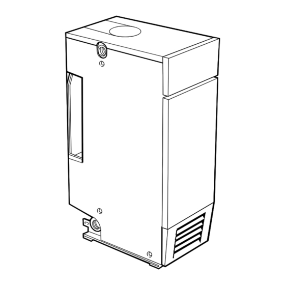
- Page 2 Mexico: The Floor Standing Gas Boiler The Ideal Mexico is a range of cast iron floor standing gas central heating boilers. Both balanced or conventional flue versions are available. A complete range of both natural gas and propane models. The range offers Super models and, for when space is tight, there are Slimline models available.
- Page 3 GENERAL Table 1 - General Data Boiler Size CF 3/40 CF 3/50 Gas Supply Connection in. BSP Rc 1/2 (1/2) Flow and Return Connections Rc 1 (1" BSP) MAXIMUM Static Water Head m (ft.) 30.5 (100) (3 bar) MINIMUM Static Water Head m (ft.) 1.0 (3.3) Electrical Supply...
-
Page 4: Table Of Contents
CONTENTS Mexico Slimline Mexico Slimline CF 3/40 G.C. No. 41 348 01 Air Supply............... 7 Mexico Slimline CF 3/50 G.C. No. 41 348 03 Boiler Assembly - Exploded view ........ 9 B.G. Certified - P.I. No. 87 AT 15 Boiler Clearances ............ -
Page 5: Gas Safety Regulations
GENERAL GAS SAFETY Health and Safety Document No. 635. The Electricity at Work Regulations, 1989. Gas Safety (Installation and Use) Regulations 1994, amendments 1996 or rules in force. Manufacturer’s notes must NOT be taken in any way as overriding It is law that all gas appliances are installed by a CORGI registered statutory obligations. -
Page 6: Boiler Clearances
GENERAL GAS SUPPLY Timber Framed Buildings If the boiler is to be fitted in a timber framed building it should be The local gas supplier should be consulted, at the installation fitted in accordance with the Institute of Gas Engineering planning stage, in order to establish the availability of an document IGE/UP/7:1998. -
Page 7: Air Supply
GENERAL FLUE INSTALLATION This device in not a substitute for an independently mounted carbon monoxide detector. The flue must be installed in accordance with the recommendations of BS. 5440:1. In cases of repeated or continuous shutdown a competent person should be called to investigate and rectify the condition The following notes are intended for general guidance: causing this and carry out an operational test after each 1. -
Page 8: Electrical Supply
GENERAL EFFECT OF AN EXTRACTOR FAN IMPORTANT If there is any type of extractor fan fitted in the premises there is The boiler must be vented. If venting cannot be done via a flow a possibility that, if an adequate air inlet area from outside is not connection a separate vent MUST be fitted by the installer. -
Page 9: Boiler Assembly - Exploded View
INSTALLATION 3 BOILER ASSEMBLY - Exploded View LEGEND 1. Heat exchanger. 21. Gas cock. 6. Front plate assembly. 2. Boiler feet assembly. 39. Split pin. 9. Main burner. 3. Thermostat pocket. 40. Diverter assembly. 15. Gas valve. 4. Cleanout cover. 41. - Page 10 INSTALLATION UNPACKING To avoid damage to the boiler casing it is recommended that the casing is removed BEFORE the boiler body is taken off the pallet. PACK CONTENTS complete boiler assembly the Hardware Pack (listed separately below) these Installation and Servicing Instructions User's Instructions.
-
Page 11: Ttb Thermostat
INSTALLATION BOILER CASING REMOVAL It is preferable to remove the casing to install the boiler. 1. Lift off the lower front panel. 2. Remove 2 screws and lift off the grille assembly. 3. Remove the gas valve cover by removing the retaining screw. -
Page 12: Preparing The Boiler
INSTALLATION PREPARING THE BOILER 2. Select the desired pumped flow tapping. Note. Before placing the boiler in the selected position any gas and 3. Connect pipe fittings to the rear tappings and plug any water connections at the rear of the boiler should be prepared, unused tappings. -
Page 13: Pump
INSTALLATION WATER CONNECTIONS Notes. 1. Connect the system flow and return pipework to the boiler a. Isolating valves must be fitted as close to the pump as as appropriate. possible. Refer to Frames 10 and 11 for guidance on system b. - Page 14 INSTALLATLON 11 GRAVITY HOT WATER & PUMPED CENTRAL HEATING 1. Separate flow and return connections are used for each service. All possible configurations are given in Frame 1 but ONLY those shown should be used. 2. The use of a cylinder thermostat is recommended. This will prevent excessive DHW temperatures and thus reduce gas consumption.
-
Page 15: Electrical Connections
INSTALLATION 12 FLUE CONNECTION Connect the flue pipe to the flue outlet. The flue pipe spigot and socket connections should be sealed with fibreglass rope or similar, and suitable fireclay cement. Notes. a. The boiler flue connection outlet size is suitable for flue pipe conforming to BS 567. -
Page 16: External Controls
INSTALLATION 15 EXTERNAL CONTROLS External wiring must be in accordance with the current I.E.E. (BS.7671) Wiring Regulations. The wiring diagrams illustrated in Frames 17- 19 cover the systems most likely to be fitted to this appliance. For wiring external controls to the Mexico Slimline 3 CF boiler reference should be made to the system wiring diagrams supplied by the relevant manufacturer, in conjunction... - Page 17 INSTALLATION 17 FULLY PUMPED - Y PLAN Notes. 1. Some earth wires are omitted for clarity. Ensure proper earth continuity when wiring. 2. Numbering of terminals on thermostats is specific to the manufacturer indicated. 3. This is a fully controlled system - set the boiler thermostat to maximum.
-
Page 18: Frost Protection
INSTALLATION 19 HONEYWELL 'C' PLAN Gravity HW & Pumped CH Notes. 1. Some earth wires are omitted for clarity. Ensure proper earth continuity when wiring 2. Numbering of terminals on thermostats is specific to the manufacturer. b blue LEGEND bk black gy grey w white br brown... -
Page 19: Fitting The Casing
INSTALLATION 21 FITTING THE CASING 1. Offer up the LH side panel and secure the panel to the baseplate and collector hood. 2. Repeat step 1 to refit the RH side panel. 3. Place the top panel on top of the side panels. -
Page 20: Initial Lighting
INSTALLATION 23 INITIAL LIGHTING LEGEND A Gas control knob B Burner pressure test point C Main burner pressure adjuster D Inlet pressure test point E Gas service cock F Sightglass G Piezo unit ignition H Boiler thermostat knob J Overheat thermostat (optional) reset button. -
Page 21: Water Circulation
INSTALLATION 24 GENERAL CHECKS 4. Water Circulation System a. With the system HOT, examine all water connections Make the following checks for correct operation: for soundness. 1. Turn the boiler thermostat OFF and ON to check that the b. With the system still hot, turn off the gas, water and main burner is extinguished and relit in response. -
Page 22: Servicing
SERVICING 26 SCHEDULE e. Check the condition of the thermocouple. f. Check that the flue is unobstructed and that the flue To ensure the continued safe and efficient operation of the system, including the flue cleanout cover, is sealed appliance, it is recommended that it is checked at regular correctly. -
Page 23: Cleaning The Burner Assembly
SERVICING 28 BURNER AND CONTROLS ASSEMBLY 1. Lift off lower front panel (refer to Frame 27) and remove the grille assembly. Undo the gas cock union 2. Undo the 2 wing nuts and washers securing the burner front plate to remove the burner/ controls assembly complete from the boiler. -
Page 24: Gas Pressure Adjustment
SERVICING 31 RE-ASSEMBLY Re-assemble the boiler in the following order : 1. Refit the flue baffle into the boiler flueway, ensuring that 5. Check the sightglass in the front plate - clean or renew as they are correctly repositioned. Refer to Frame 6. necessary. -
Page 25: Replacement Of Parts
SERVICING REPLACEMENT OF PARTS 33 GENERAL 34 SIGHTGLASS REPLACEMENT 1. Unfasten the two wing nuts and washers. Remove the assembly from the When replacing any component: front plate. 2. Fit the new 1. Isolate the electricity supply. sightglass and re- assemble in the 2. -
Page 26: Controls Panel Replacement
SERVICING 37 BOILER THERMOSTAT REPLACEMENT 1. Lift off the front lower panel - Refer to Frame 27. 2. Pull off the thermostat knob. 3. Remove the 2 screws and pull down the control panel tabs clear of the top panel. 4. -
Page 27: Overheat Thermostat Replacement
SERVICING 39 OVERHEAT THERMOSTAT REPLACEMENT 1. Lift off the lower front panel. Refer to Frame 27. 2. Remove the 2 screws and pull down the control panel tabs to clear the top panel. 3. Remove the split pin at the thermostat pocket and withdraw the phials from the pocket. -
Page 28: Ignition Electrode Replacement
SERVICING 41 IGNITION ELECTRODE REPLACEMENT 1. Lift off lower front panel and remove the grille assembly. Undo the gas cock union. Remove the burner and controls assembly. Refer to Frames 27 & 28. 2. Pull off the ignition lead at the electrode. The electrode is secured by a nut. -
Page 29: Main Burner Replacement
SERVICING 43 MAIN BURNER REPLACEMENT 1. Lift off lower front panel and remove the grille assembly. Undo the gas cock union. Remove the burner and controls assembly. Refer to Frames 27 & 28. Undo the 2 wing nuts and remove the burner and controls assembly. -
Page 30: Gas Valve Replacement
SERVICING 45 GAS VALVE REPLACEMENT 1. Lift off lower front panel and remove the grille assembly. Undo the gas cock union. Remove the burner and controls assembly. Refer to Frames 27 & 28. 2. Undo the pilot pipe and thermocouple connections at the gas valve. -
Page 31: Fault Finding
FAULT FINDING Before attempting any electrical fault finding ALWAYS carry Detailed instructions on the cleaning and adjustment out preliminary electrical system checks, i.e. earth continuity, or replacement of faulty components are contained in polarity and resistance to earth using a suitable meter. the 'Servicing' section of this publication. -
Page 32: Short List Of Parts
SHORT LIST OF PARTS The following are parts commonly required as replacement When ordering spares please quote: components, due to damage or expendability. Their failure or absence is likely to affect safety or performance of this appliance. 1. Boiler model 2. - Page 33 LIST OF PARTS 50 SHORT PARTS Mexico Slimline CF 3/40 & 3/50 - Installation...
- Page 34 LIST OF PARTS 51 BURNER AND CONTROLS ASSEMBLY - Exploded View Legend 6. Front plate assembly 16. 'O' ring. 7. Sightglass assembly. 17. Piezo unit. 8. Pilot pipe. 18. Ignition electrode. 9. Main burner. 19. Ignition (HT) lead. 11. Main burner injector. 20.
- Page 35 LIST OF PARTS 52 CONTROL BOX ASSEMBLY - Exploded View Legend 23. Control panel complete. 24. Control box. 25. Control thermostat. 26. Thermostat knob. 27. Controls panel. 28. Magnetic strip. 29. Controls front panel. Mexico Slimline CF 3/40 & 3/50 - Installation...
-
Page 36: Boiler Casing Assembly
LIST OF PARTS 53 BOILER CASING ASSEMBLY Legend 22. Casing complete. 23. Control panel complete. 32. L.H. side panel. 33. R.H. side panel. 34. Top panel. 35. Grille panel. 36. Front lower panel. 37. Top panel infill piece. Mexico Slimline CF 3/40 & 3/50 - Installation... - Page 37 Mexico Slimline CF 3/40 & 3/50 - Installation...
- Page 38 For details of courses please ring: ....01270 413 624 September 1999 151 905 A04 Ideal Installer/Technical Helpline Tel: 01482 498 663 Mexico Slimline CF 3/40 & 3/50 - Installation...
- Page 39 Your feedback and your chance to win a free boiler At Ideal we've been leaders in the design and engineering of robust and reliable boilers for over 90 years. We want to continue as leaders by listening to your suggestions for how to improve our boilers and our service.
-
Page 40: Further Information
Further information If you would like information about Ideal Boilers please complete this sheet and fax it to us on 01482 498699 or post it to Caradon Plumbing Limited, PO Box 103, National Avenue, Kingston upon Hull, HU5 4JN. Installer details...