Advertisement
Table of Contents
- 1 Wall Mounted
- 2 Outline and Dimensions
- 3 Safety Precautions
- 4 Installation of the Outdoor Unit
- 5 Installation Manual
- 6 Installation of the Indoor Unit
- 7 Refrigerant Piping Work
- 8 Electrical Wiring Connection
- 9 Vacuuming and Charging
- 10 Indicator Lights
- 11 Air Conditioner Unit Operation
- 12 Standard Operating Conditions
- 13 Auto Random Re-Start Function
- 14 Service and Maintenance
- 15 Troubleshooting
- Download this manual
Advertisement
Table of Contents

Summary of Contents for Daikin FT20FV1M
-
Page 1: Wall Mounted
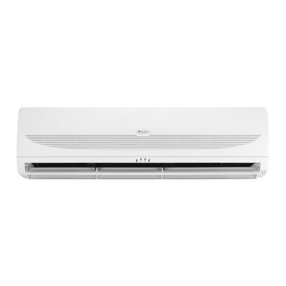
INSTALLATION MANUAL WALL MOUNTED SPLIT TYPE AIR CONDITIONER WALL MOUNTED Part No.: R08019028786 IM-WMG-0906-DAIKIN... -
Page 3: Outline And Dimensions
Indoor Unit TOP VIEW FRONT VIEW SIDE VIEW INSTALLATION PLATE All dimensions are in mm/ (in) Dimension FT20FV1M/FT25FV1M (31.5) (10.2) (7.8) (15.0) (9.7) (7.3) (4.9) (0.3) (2.2) (2.0) (12.6) (15.0) (2.0) (5.1) (5.2) FT28FV1M/FT35FV1M (35.4) (10.2) (7.8) (23.2) (9.7) (7.3) (4.9) (0.3) - Page 4 Outdoor Unit Dimension R20FV1M/R25FV1M (23.6) (18.7) (9.6) R35FV1M (27.5) (20.5) (9.8) Dimension R20FV1M/R25FV1M (16.4) (6.9) (1.3) R35FV1M (19.1) (6.8) (1.4) Dimension R20FV1M/R25FV1M (3.6) (3.1) (3.2) R35FV1M (3.7) (3.6) (3.3) Dimension R20FV1M/R25FV1M (2.2) (15.6) (3.9) R35FV1M (2.6) (17.3) (5.1) Dimension R20FV1M/R25FV1M (3.8) (0.6) (0.8) R35FV1M All dimensions are in mm/ (in)
-
Page 5: Safety Precautions
This manual provides the procedures of installation to ensure a safe and good standard of operation for the air condi- tioner unit. Special adjustment may be necessary to suit local requirements. Before using your air conditioner, please read this instruction manual carefully and keep it for future reference. MODEL Indoor Outdoor FT20FV1M R20FV1M FT25FV1M R25FV1M FT35FV1M R35FV1M FT50FV1M... -
Page 6: Installation Of The Indoor Unit
INSTALLATION OF THE INDOOR UNIT The indoor unit must be installed in such a way so as to prevent short circuit of 50.0 mm 50.0 mm the cool discharged air with the hot return air. Please follow the installation clearance shown in the figure. Do not place the indoor unit where there could be direct sunlight shining on it. -
Page 7: Refrigerant Piping Work
As a result, the compressor may become defective. Always choose the shortest path and follow the recommendations as tabulated below: Outdoor Unit Model FT20FV1M FT25FV1M FT28FV1M FT35FV1M FT50FV1M FT60FV1M9 Maximum length, m (ft), L 12 (39) 12 (39) -
Page 8: Electrical Wiring Connection
Indoor Unit Terminal Block Terminal Block COMP COMP Power Supply Cable There must be a double pole switch with a minimum 3mm contact gap and FT20FV1M FT50FV1M fuse/circuit breaker as recommended FT25FV1M FT60FV1M9 in the fixed installation circuit. Model FT28FV1M... -
Page 9: Vacuuming And Charging
If the piping length is more than 7.62m (25ft), then use the additional charge valve as indicated in the table. Additional charge in gram (For R22 models) Model 10m/32.8ft 12m/39.4ft 15m/49.2ft FT20FV1M / FT25FV1M FT28FV1M/FT35FV1M FT50FV1M FT60FV1M9 Charge Operation This operation must be done by using a gas cylinder and a precise weigh-... -
Page 10: Indicator Lights
INDICATOR LIGHTS IR Signal Receiver When an infrared remote control operating signal has been transmitted, the signal receiver on the indoor unit will make a <beep> sound to confirm acceptance of the signal transmis- sion. IR Receiver Cooling Unit LED Indicator Lights The table shows the LED indicator lights for the air conditioner unit under normal operation and fault conditions. -
Page 11: Air Conditioner Unit Operation
AIR CONDITIONER UNIT OPERATION Dry Mode Frost Prevention • When the air humidity is high, the unit can operate in dry • When the air filter is dirty, the evaporating temperature will mode. Press <MODE> button and choose <DRY>. decrease and eventually cause frosting. •... -
Page 12: Auto Random Re-Start Function
INSTALLATION OF UNIT WITH O2 THERAPY FEATURE 3. Insert the end hose to the connector (indoor) Hose Refrigerant Piping 2. Insert the end hose to the connector (outdoor) 1. Open valve cover to connecting the hose AUTO RANDOM RE-START FUNCTION If there is a power cut when the unit is operating, it will automatically resume the same operating mode when the power is restored. - Page 13 Off the unit. Unscrew the air discharge housing. Flip open the air discharge housing. Clean the blower. Close the air discharge housing and tighten it with screw. ! CAUTION Do not operate any heating apparatus too close to the air conditioner unit. This may cause the plastic panel to melt or deform as a result of the excessive heat.
-
Page 14: Troubleshooting
TROUBLESHOOTING If any malfunction of the air conditioner unit is noted, immediately switch off the power supply to the unit. Check the following fault conditions and causes for some simple troubleshooting tips. Fault Causes / Action 1. The compressor does not operate 3 minutes after the air - Protection against frequent starting. - Page 16 • In the event that there is any conflict in the interpretation of this manual and any translation of the same in any languages, the ENGLISH version of this manual shall prevail. • The manufacturer reserves right to revise any of the specification and design contain herein at any time without prior notification. OYL MANUFACTURING COMPANY SDN.


