Table of Contents
Advertisement
Advertisement
Table of Contents

Related Manuals for LevelOne WBR-6804


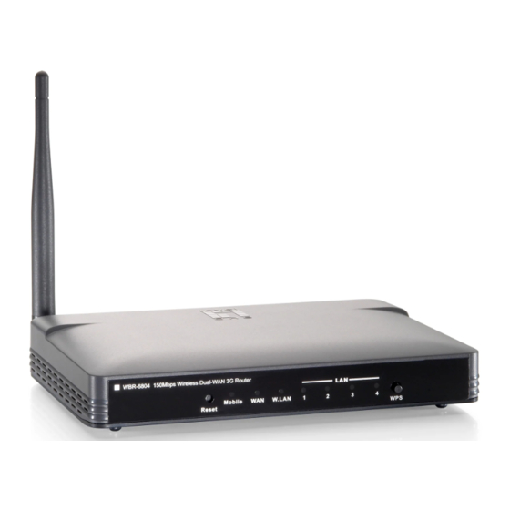
Summary of Contents for LevelOne WBR-6804
-
Page 1: User Manual
LevelOne User Manual WBR-6804 150Mbps Wireless Dual-WAN 3G Router Ver. 1.0... - Page 2 Council Directive 89/336/EEC on the approximation of the laws of the Member States relating to electromagnetic compatibility. CE Marking Warning Hereby, Digital Data Communications, declares that this product is in compliance with the essential requirements and other relevant provisions of Directive 1999/5/EC. The CE-Declaration of Conformity can be downloaded at: http://www.levelone.eu/support.php...
-
Page 3: General Public License
If you would like a copy of the GPL or other open source code in this software on a physical CD medium, LevelOne (Digital Data Communications) offers to mail this CD to you upon request, for a price of US$9.99 plus the cost of shipping. -
Page 4: Table Of Contents
3.5 TOOL BOX ........................56 CHAPTER 4 . TROUBLESHOOTING ................61 APPENDIX A. SPEC SUMMARY TABLE ................65 APPENDIX B. LICENSING INFORMATION ................66 Default Settings IP Address 192.168.1.1 Password admin Wireless Mode Enable Wireless SSID LevelOne Wireless Security None... -
Page 5: Chapter 1 Introduction
WCDMA or EVDO and even HSDPA as well, and supports wireless data transfers up to 150M bps, and wired data transfers up to 100 Mbps. The WiFi Combo Router is compatible with industry security features. 1.1 Package List WBR-6804 Power Adapter RJ-45 LAN Cable Quick Installation Guide... - Page 6 Power JACK WAN PORT LAN PORT USB PORT B. LED indicators Indicator Description Green and Steady On USB 3G connection is established USB 3G Green and Blinking Data packet transferred via USB 3G Green and Steady On Ethernet WAN connection is established Ethernet WAN Green and Blinking Data packet transferred via Ethernet WAN...
- Page 7 C. Installation Steps DO NOT Note: connect the router to power before performing the installation steps below. Step 1. Plug a USB modem into USB port. Step 2. Insert RJ45 cable into LAN Port on the back panel of the router. Then plug the other end of into computer. Step 3.
-
Page 8: Chapter 2 Getting Started With Easy Setup Utility
Chapter 2 Getting Started with Easy Setup Utility There are two approaches for you to set up the Wi-Fi Combo Router quickly and easily. One is through executing the provided Windows Easy Setup Utility on your PC, and the other is through browsing the device web pages and configuration. - Page 9 Step 4: Click “Next” to continue. Step 5: Select Wireless Enable, and then click “Next” to continue. Step 6: Enter SSID, Channel and Security options, and then click “Next” to continue.
- Page 10 Step 7: Click” Let me select WAN service by myself” to select WAN service manually. Step 8: Select 3G Service by clicking 3G icon to continue. Step 9-1: Select “Auto-Detection” and the Utility will try to detect and configure the required 3G service settings automatically.
- Page 11 Step 9-2: Or you can select “Manual” and manually fill in the required 3G service settings provided by your ISP. Click “Next” to continue. Step 10: Click “Next” to save your setting. Step 11: The Wi-Fi Combo Router is rebooted to make your entire configuration take effect.
- Page 12 Step 12: Click “Next” to test the Internet connection or you can ignore test. Step 13: Click “Next” to test WAN Networking service. Step 14: Setup is completed.
-
Page 13: Easy Setup By Configuring Web
2.2 Easy Setup by Configuring Web Pages You can also browse web UI to configure the device. Browse to Activate the Setup Wizard Type in the IP Address (http://192.168.1.1) Type in the default password “admin” in the System Password and then click ‘login’... - Page 14 Configure with the Setup Wizard Step 1 Change System Password. Set up your system password. (Default:admin) Step 2: Select Time Zone Step 3: Select WAN Type. Choose Auto-Detecting or Manually to set WAN Type.
- Page 15 Step 4: Select Wan Type. If you want to use 3G service as the main internet access, please set the WAN interface as “Wireless WAN” and the WAN type as “3G”. Step 5: 3G Mode. Select Auto-Detection then click “Next” to continue. Step 6: Set up your Wireless Network.
- Page 16 Step 7: Setup your Encryption Key here, then click”Next” to continue. Step 8: Apply your Setting. Then click Apply Setting. Step 9: Click Finish to complete it.
-
Page 17: Chapter 3 Making Configuration
Chapter 3 Making Configuration Whenever you want to configure your network or this device, you can access the Configuration Menu by opening the web-browser and typing in the IP Address of the device. The default IP Address is: 192.168.1.1 Enter the default password “admin” in the System Password and then click ‘login’ button. Then, you can browse the “Advanced”... -
Page 18: Network Setup
3.1.1. Network Setup LAN IP Address: The local IP address of this device. The computers on your network must use the LAN IP address of this device as their Default Gateway. You can change it if necessary. Subnet Mask: Input your Subnet mask. (All devices in the network must have the same subnet mask.) The default subnet mask is 255.255.255.0. - Page 19 A. 3G...
- Page 20 1. WAN Type: Choose 3G for WAN connection. 2. Dial-Up Profile: Please select Auto-Detection or Manual. You can choose “Auto-Detection”, and the router will try to detect and configure the required 3G service settings automatically. Otherwise, you can select “Manual”, and manually fill in the required 3G service settings provided by your carrier or ISP.
- Page 21 B. iBurst 1. WAN Type: Choose iBurst for WAN connection. 2. Account: Enter the User Name for iBurst connection. 3. Password: Enter new Password for iBurst connection. 4. Primary DNS: You can assign a Primary DNS server if required. (Optional) 5.
- Page 22 10. Maximum Transmission Unit (MTU): You can change MTU value if required. The default MTU value is set to 0 (auto). 11. NAT disable: You can disable NAT feature if required. C. Static IP Address 1. WAN Type: Choose Static IP Address. 2.
- Page 23 D. Dynamic IP Address 1. WAN Type: Choose Dynamic IP Address. 2. Host Name: Optional, required by some ISPs, for example, @Home. 3. ISP registered MAC Address: Some ISP (Cable company) will record your MAC address on PC. You can press “Clone” button to copy the MAC address on your PC here, or you can input it manually.
- Page 24 E. PPP over Ethernet 1. WAN Type: Choose PPP over Ethernet. 2. PPPoE Account and Password: The account and password your ISP assigned to you. 3. Primary DNS: You can indicate IP address of primary DNS if required. 4. Secondary DNS: You can indicate IP address of secondary DNS if required. 5.
- Page 25 F. PPTP 1. WAN Type: Choose PPTP. 2. IP Mode: You can select “Static IP Address” or “Dynamic IP Address”. 3. My IP Address*, My Subnet Mask*, and Gateway IP*: The IP address, subnet mask, and IP address of gateway your ISP assigned to you. 4.
- Page 26 G. L2TP 1. WAN Type: Choose L2TP. 2. IP Mode: You can select “Static IP Address” or “Dynamic IP Address”. 3. My IP Address*, My Subnet Mask*, and Gateway IP*: The IP address, subnet mask, and IP address of gateway your ISP assigned to you. 4.
- Page 27 . Combo WAN Setting With Combo WAN feature, you can choose one primary WAN connection, and set another WAN connection for backup. The combo WAN status will be showed at Internet Setup page. Press “Settings” button to configure this feature. At Combo WAN setting page, you can choose Disable, or Failover options.
- Page 28 Failover With this function enabled, when the primary WAN connection is broken, the device will automatically switch to secondary WAN connection and keep you connected to Internet. Meanwhile, if the device detects that the primary WAN connection is recovered, your Internet connection will be switched from secondary WAN back to primary WAN.
-
Page 29: Dhcp Server
3.1.2. DHCP Server 1. DHCP Server: Choose either Disable or Enable. If you enable the DHCP Server function, the following settings will be effective. 2. IP Pool Starting/Ending Address: Whenever there is a request, the DHCP server will automatically allocate an unused IP address from the IP address pool to the requesting computer. - Page 30 Press “Fixed Mapping” and the DHCP Server will reserve the special IP for designated MAC address.
-
Page 31: Wireless Settings
3.1.3. Wireless Settings Wireless settings allow you to set the wireless configuration items. 1. Wireless Module: You can enable or disable wireless function. 2. Network ID (SSID): Network ID is used for identifying the Wireless LAN (WLAN). Client stations can roam freely over this device and other Access Points that have the same Network ID. - Page 32 Open system authentication simply consists of two communications. The first is an authentication request by the client that contains the station ID (typically the MAC address). This is followed by an authentication response from the AP/router containing a success or failure message. An example of when a failure may occur is if the client's MAC address is explicitly excluded in the AP/router configuration.
- Page 33 WPA-PSK/WPA-PSK2 Another encryption options for WPA-PSK-TKIP and WPA-PSK2-AES, the others are same the WPA-PSK. WPA/WPA2 Another encryption options for WPA-TKIP and WPA2-AES, the others are same the WPA. By pressing “WPS Setup”, you can configure and enable the easy setup feature WPS (Wi-Fi Protection Setup) for your wireless network.
-
Page 34: Change Password
3.1.4. Change Password You can change the System Password here. We strongly recommend you to change the system password for security reason. Click on “Save” to store your settings or click “Undo” to give up the changes. -
Page 35: Forwarding Rules
3.2 Forwarding Rules... -
Page 36: Virtual Server
3.2.1 Virtual Server This product’s NAT firewall filters out unrecognized packets to protect your Intranet, so all hosts behind this product are invisible to the outside world. If you wish, you can make some of them accessible by enabling the Virtual Server Mapping. A virtual server is defined as a Service Port, and all requests to this port will be redirected to the computer specified by the Server IP. - Page 37 For example, if you have an FTP server (port 21) at 192.168.1.2, a Web server (port 80) at 192.168.1.4, and a VPN server at 192.168.1.6, then you need to specify the following virtual server mapping table: Service Port Server IP Enable 192.168.1.2 192.168.1.4...
-
Page 38: Special Ap
3.2.2 Special AP Some applications require multiple connections, like Internet games, Video conferencing, Internet telephony, etc. Because of the firewall function, these applications cannot work with a pure NAT router. The Special Applications feature allows some of these applications to work with this product. -
Page 39: Miscellaneous
3.2.3 Miscellaneous 1. IP Address of DMZ Host DMZ (Demilitarized Zone) Host is a host without the protection of firewall. It allows a computer to be exposed to unrestricted 2-way communication for Internet games, Video conferencing, Internet telephony and other special applications. 2. -
Page 40: Security Setting
3.3 Security Setting... - Page 41 3.3.1 Packet Filters Packet Filter includes both outbound filter and inbound filter. And they have same way to setting. Packet Filter enables you to control what packets are allowed to pass the router. Outbound filter applies on all outbound packets. However, inbound filter applies on packets that destined to Virtual Servers or DMZ host only.
- Page 42 • Use Rule# For source or destination IP address, you can define a single IP address (4.3.2.1) or a range of IP addresses (4.3.2.1-4.3.2.254). An empty implies all IP addresses. For source or destination port, you can define a single port (80) or a range of ports (1000-1999).
-
Page 43: Domain Filters
3.3.2 Domain Filters Domain Filter prevents users under this device from accessing specific URLs. 1. Domain Filter: Check if you want to enable Domain Filter. 2. Log DNS Query: Check if you want to log the action when someone accesses the specific URLs. - Page 44 3.3.3 URL Blocking URL Blocking will block LAN computers to connect with pre-define Websites. The major difference between “Domain filter” and “URL Blocking” is Domain filter require user to input suffix (like .com or .org, etc), while URL Blocking require user to input a keyword only. In other words, Domain filter can block specific website, while URL Blocking can block hundreds of websites by simply a keyword.
-
Page 45: Mac Control
3.3.4 MAC Control MAC Address Control allows you to assign different access right for different users and to assign a specific IP address to a certain MAC address. 1. MAC Address Control: Check “Enable” to enable the “MAC Address Control”. All of the settings in this page will take effect only when “Enable”... - Page 46 3.3.5 Miscellaneous 1. Administrator Time-out: The time of no activity to logout automatically, you may set it to zero to disable this feature. 2. Remote Administrator Host/Port In general, only Intranet user can browse the built-in web pages to perform administration task.
-
Page 47: Advanced Setting
3.4 Advanced Setting... -
Page 48: System Log
3.4.1 System Log This page support two methods to export system logs to specific destination by means of syslog (UDP) and SMTP(TCP). The items you have to setup including: 1. IP Address for Sys log: Host IP of destination where sys log will be sent to. Check Enable to enable this function. -
Page 49: Dynamic Dns
3.4.2 Dynamic DNS To host your server on a changing IP address, you have to use dynamic domain name service (DDNS). So that anyone wishing to reach your host only needs to know the name of it. Dynamic DNS will map the name of your host to your current IP address, which changes each time you connect your Internet service provider. - Page 50 3.4.3 QOS Provide different priority to different users or data flows, or guarantee a certain level of performance. 1. QOS Control: Check Enable to enable this function. 2. Bandwidth of Upstream: Set the limitation of upstream bandwidth 3. Local IP : Ports: Define the Local IP address and ports of packets 4.
- Page 51 3.4.4 SNMP In brief, SNMP, the Simple Network Management Protocol, is a protocol designed to give a user the capability to remotely manage a computer network by polling and setting terminal values and monitoring network events. 1. Enable SNMP: You must check “Local”, “Remote” or both to enable SNMP function. If “Local”...
- Page 52 3.4.5 Routing If you have more than one routers and subnets, you will need to enable routing table to allow packets to find proper routing path and allow different subnets to communicate with each other. The routing table allows you to determine which physical interface address to use for outgoing IP data grams.
-
Page 53: System Time
3.4.6 System Time 1. Time Zone: Select a time zone where this device locates. 2. Auto-Synchronization: Check the “Enable” checkbox to enable this function. Besides, you can select a NTP time server to consult UTC time. 3. Sync with Time Server: Click on the button if you want to set Date and Time by NTP Protocol manually. - Page 54 3.4.7 Scheduling You can set the schedule time to decide which service will be turned on or off. 1. Schedule: Check to enable the schedule rule settings. 2. Add New Rule: To create a schedule rule, click the “Add New Rule” button. You can edit the Name of Rule, Policy, and set the schedule time (Week day, Start Time, and End Time).
- Page 55 Click on “Save” to store your settings or click “Undo” to give up the changes.
-
Page 56: Tool Box
3.5 Tool Box... - Page 57 3.5.1 System Info You can view the System Information and System log, and download/clear the System log, in this page.
- Page 58 3.5.2 Firmware Upgrade You can upgrade firmware by clicking “Upgrade” button. 3.5.3 Backup Setting You can backup your settings by clicking the “Backup Setting” function item and save it as a bin file. Once you want to restore these settings, please click Firmware Upgrade button and...
- Page 59 use the bin file you saved. 3.5.4 Reset to Default You can also reset this device to factory default settings by clicking the Reset to default function item. 3.5.5 Reboot You can also reboot this device by clicking the Reboot function item.
- Page 60 3.5.6 Miscellaneous 1. MAC Address for Wake-on-LAN: Enter the MAC address of a local PC, and press “Wake Up” button to turn it on. Please note the local PC needs to support Wake-on-LAN to make this feature work. 2. Domain Name or IP address for Ping Test: Allow you to configure an IP, and ping the device.
-
Page 61: Chapter 4 . Troubleshooting
Chapter 4 . Troubleshooting This Chapter provides solutions to problems for the installation and operation of the WiFi Combo Router. You can refer to the following if you are having problems. 1 Why can’t I configure the router even the cable is plugged and the LED is lit? Do a Ping test to make sure that the WiFi Combo Note:... - Page 62 Right-click on Wireless Card bus Adapter or your specific network adapter. Select Properties to ensure that all drivers are installed properly. Look under Device Status to see if the device is working properly. Click “OK”. 2 What can I do if my Ethernet connection does not work properly? Make sure the RJ45 cable connect with the router.
- Page 63 information. Why my 3G connection is keep dropping? Please check 3G signal strength from your ISP in your environment is above middle level. 4 Something wrong with the wireless connection? Can’t setup a wireless connection? Ensure that the SSID and the encryption settings are exactly the same to the Clients.
- Page 64 microwaves, monitors, electric motors, etc. 5 What to do if I forgot my encryption key? 1. Go back to advanced setting to set up your Encryption key again. 2. Reset the WiFi Combo Router to default setting 6 How to reset to default? 1.
-
Page 65: Appendix A. Spec Summary Table
Appendix A. Spec Summary Table 3G Access USB port Standards IEEE 802.11b/g IEEE 802.3 IEEE 802.3u Wireless Standard IEEE 802.11 B\G\N 11B: 11, 5.5, 2, 1 Mbps Data Rate 11G: 54, 48, 36, 24, 18, 12, 9, and 6 Mbps 11N: Max physical rate up to 150Mbps Frequency 2.4 –... -
Page 66: Appendix B. Licensing Information
Appendix B. Licensing information This product includes copyrighted third-party software licensed under the terms of the GNU General Public License. Please refer to the GNU General Public License below to check the detailed terms of this license. The following parts of this product are subject to the GNU GPL, and those software packages are copyright by their respective authors. -
Page 67: Gnu General Public License
GNU GENERAL PUBLIC LICENSE Version 2, June 1991 Copyright (C) 1989, 1991 Free Software Foundation, Inc. 59 Temple Place, Suite 330, Boston, MA 02111-1307 USA Everyone is permitted to copy and distribute verbatim copies of this license document, but changing it is not allowed. Preamble The licenses for most software are designed to take away your freedom to share and change it. - Page 68 GNU GENERAL PUBLIC LICENSE TERMS AND CONDITIONS FOR COPYING, DISTRIBUTION AND MODIFICATION 0. This License applies to any program or other work which contains a notice placed by the copyright holder saying it may be distributed under the terms of this General Public License. The "Program", below, refers to any such program or work, and a "work based on the Program"...
- Page 69 a) Accompany it with the complete corresponding machine-readable source code, which must be distributed under the terms of Sections 1 and 2 above on a medium customarily used for software interchange; or, b) Accompany it with a written offer, valid for at least three years, to give any third party, for a charge no more than your cost of physically performing source distribution, a complete machine-readable copy of the corresponding source code, to be distributed under the terms of Sections 1 and 2 above on a medium customarily used for software interchange;...
- Page 70 integrity of the free software distribution system, which is implemented by public license practices. Many people have made generous contributions to the wide range of software distributed through that system in reliance on consistent application of that system; it is up to the author/donor to decide if he or she is willing to distribute software through any other system and a licensee cannot impose that choice.