Table of Contents
Advertisement
Quick Links
Advertisement
Table of Contents

Related Manuals for LevelOne WBR-6005


Summary of Contents for LevelOne WBR-6005
-
Page 1: User Manual
LevelOne User Manual WBR-6005 150Mbps N Wireless Router Ver. 1.0... - Page 2 S E R UID E WBR-6005 150M N W IRELESS OUTER IEEE 802.11n 150 Mbps Wirelesss Gateway Router, with Four 10/100BASE-TX LAN ports, and One 10/100BASE-TX WAN port WBR-6005 E122009-CS-R01 149100000068W...
-
Page 3: Compliances
OMPLIANCES EDERAL OMMUNICATION OMMISSION This equipment has been tested and found to comply with the limits for a Class B digital device, pursuant to Part 15 of the FCC Rules. These limits are designed to provide reasonable protection against harmful interference in a residential installation. - Page 4 IC S TATEMENT This Class B digital apparatus complies with Canadian ICES-003. Operation is subject to the following two conditions: (1) this device may not cause interference, and (2) this device must accept any interference, including interference that may cause undesired operation of the device. Cet appareil numérique de la classe B conforme á...
- Page 5 This device is intended for use in the following European Community and EFTA countries: ◆ ◆ ◆ Austria Belgium Bulgaria ◆ Denmark ◆ Estonia ◆ Finland ◆ ◆ ◆ Greece Hungary Iceland ◆ ◆ ◆ Latvia Lithuania Luxembourg ◆ Norway ◆...
- Page 6 German Hiermit erklärt Manufacturer, dass sich dieser/diese/dieses Radio LAN device in Deutsch Ü bereinstimmung mit den grundlegenden Anforderungen und den anderen relevanten Vorschriften der Richtlinie 1999/5/EG befindet". (BMWi) Hiermit erklärt Manufacturer die Ü bereinstimmung des Gerätes Radio LAN device mit den grundlegenden Anforderungen und den anderen relevanten Festlegungen der Richtlinie 1999/5/EG.
-
Page 7: About This Guide
BOUT This guide gives specific information on how to install the Wireless Router URPOSE and its physical and performance related characteristics. It also gives information on how to operate and use the management functions of the Wireless Broadband Router. This guide is for users with a basic working knowledge of computers. You UDIENCE should be familiar with Windows operating system concepts. -
Page 8: Table Of Contents
ONTENTS OMPLIANCES BOUT ONTENTS IGURES ABLES ECTION ETTING NTRODUCTION Key Hardware Features Description of Capabilities Applications Package Contents Hardware Description LED Indicators Ethernet WAN Port Ethernet LAN Ports Power Connector Reset Button WPS Button ETWORK Internet Gateway Router LAN Access Point Wireless Bridge NSTALLING THE System Requirements... - Page 9 Mounting on a Horizontal Surface Router Mode Connections Bridge Mode Connections NITIAL ISP Settings Connecting to the Login Page Home Page and Main Menu Common Web Page Buttons Setup Wizard Step 1 - Language Selection Step 2 - Time Settings Step 3 - WAN Settings - DHCP Step 3 - WAN Settings - Static IP Step 3 - WAN Settings - PPPoE...
- Page 10 Routing Table Dynamic Route IRELESS ONFIGURATION Basic Settings HT Physical Mode Settings Advanced Settings Advanced Wireless Wi-Fi Multimedia Multicast-to-Unicast Converter WLAN Security Wired Equivalent Privacy (WEP) WPA Pre-Shared Key WPA Enterprise Mode IEEE 802.1X and RADIUS Access Policy Wireless Distribution System (WDS) Wi-Fi Protected Setup (WPS) Station List IREWALL...
- Page 11 ECTION PPENDICES ROUBLESHOOTING Diagnosing LED Indicators If You Cannot Connect to the Internet Before Contacting Technical Support ARDWARE ABLES AND Twisted-Pair Cable Assignments 10/100BASE-TX Pin Assignments Straight-Through Wiring Crossover Wiring ICENSE The GNU General Public License LOSSARY NDEX PECIFICATIONS INOUTS NFORMATION –...
-
Page 12: Figures
IGURES Figure 1: Top Panel Figure 2: Rear Panel Figure 3: LEDs Figure 4: Operating as an Internet Gateway Router Figure 5: Operating as an Access Point Figure 6: Operating as a Wireless Bridge Figure 7: Operating as a Wireless Repeater Figure 8: Wall Mounting Figure 9:... - Page 13 Figure 32: Basic Settings Figure 33: HT Physical Mode Settings Figure 34: Advanced Wireless Settings Figure 35: Wi-Fi Multimedia Settings Figure 36: WMM Configuration Figure 37: Multicast-to-Unicast Converter Figure 38: Security Mode Options Figure 39: Security Mode - WEP Figure 40: Security Mode - WPA-PSK Figure 41: Security Mode - WPA...
-
Page 14: Tables
ABLES Table 1: Key Hardware Features Table 2: LED Behavior Table 3: WMM Access Categories Table 4: LED Indicators 10/100BASE-TX MDI and MDI-X Port Pinouts Table 5: – 14 –... -
Page 15: Sectioni
ECTION ETTING This section provides an overview of the Wireless Router, and describes how to install and mount the unit. It also describes the basic settings required to access the management interface and run the setup Wizard. This section includes these chapters: ―Introduction‖... -
Page 16: Introduction
NTRODUCTION The 150M N Wireless Router (WBR-6005) supports routing from an Internet Service Provider (ISP) connection (DSL or cable modem) to a local network. It is simple to configure and can be up and running in minutes. ARDWARE EATURES The following table describes the main hardware features of the Wireless Router. -
Page 17: Applications
Easy setup through a Web browser on any operating system that ◆ supports TCP/IP. Compatible with all popular Internet applications. ◆ In addition, the Wireless Router offers full network management capabilities through an easy-to-configure web interface. Many advanced networking features are provided by the Wireless Router: PPLICATIONS Wired LAN —... -
Page 18: Package Contents
Wireless Router are briefly described below. ■ ■ ■ ACKAGE ONTENTS The Wireless Router package includes: WBR-6005 150M N Wireless Router ◆ RJ-45 Category 5 network cable ◆ AC power adapter ◆ Quick Installation Guide ◆... -
Page 19: Hardware Description
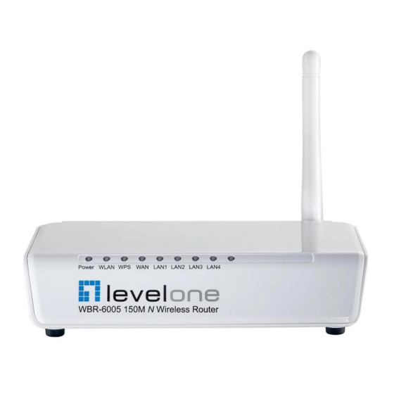
| Introduction HAPTER Hardware Description ARDWARE ESCRIPTION The Wireless Router connects to the Internet using its RJ-45 WAN port. It connects directly to your PC or to a local area network using its RJ-45 Fast Ethernet LAN ports. The Wireless Router includes an LED display on the front panel for system power and port indications that simplifies installation and network troubleshooting. -
Page 20: Led Indicators
Figure 2: Rear Panel WPS Button RJ-45 WAN Port The Wireless Router includes eight status LED indicators, as described in LED I NDICATORS the following figure and table. Figure 3: LEDs RJ-45 LAN Ports Power WLAN – 20 – | Introduction HAPTER Hardware Description Reset Button... -
Page 21: Ethernet Wan Port
Table 2: LED Behavior Power WLAN LAN1~LAN4 A 100BASE-TX RJ-45 port that can be attached to an Internet access WAN P THERNET device, such as a DSL or Cable modem. The Wireless Router has four 100BASE-TX RJ-45 ports that can be attached THERNET directly to 10BASE-T/100BASE-TX LAN segments. -
Page 22: Reset Button
This button is used to restore the factory default configuration. If you hold ESET UTTON down the button for 5 seconds or more, any configuration changes you may have made are removed, and the factory default configuration is restored to the Wireless Router. Press to automatically configure the Wireless Router with other WPS WPS B UTTON... -
Page 23: Network Planning
ETWORK The Wireless Router is designed to be very flexible in its deployment options. It can be used as an Internet gateway for a small network, or as an access point to extend an existing wired network to support wireless users. -
Page 24: Lan Access Point
The private local network, connected to the LAN port or wireless interface, provides a Dynamic Host Configuration Protocol (DHCP) server for allocating IP addresses to local PCs and wireless clients, and Network Address Translation (NAT) for mapping the multiple ―internal‖ IP addresses to one ―external‖... -
Page 25: Wireless Bridge
IRELESS RIDGE The IEEE 802.11 standard defines a Wireless Distribution System (WDS) for bridge connections between access points. The Wireless Router can use WDS to forward traffic on links between units. Up to four WDS links can be specified for the Wireless Router. The WDS feature enables two basic functions to be configured in the wireless network. -
Page 26: Installing The Wireless Router
NSTALLING THE The Wireless Router has two basic operating modes that can be set through the web-based management interface. For information on setting the mode suitable for your network environment. page Router Mode — A gateway mode that connects a wired LAN and ◆... -
Page 27: Mounting The Device
OUNTING THE EVICE The Wireless Router can be mounted on any horizontal surface, or on a wall. The following sections describe the mounting options. The Wireless Router should be mounted only to a wall or wood surface that OUNTING ON A is at least 1/2-inch plywood or its equivalent. -
Page 28: Mounting On A Horizontal Surface
To keep the Wireless Router from sliding on the surface, the Wireless OUNTING ON A Router has four rubber feet on the bottom of the unit. ORIZONTAL URFACE It is recommended to select an uncluttered area on a sturdy surface, such as a desktop or table. -
Page 29: Bridge Mode Connections
Set up wireless devices by pressing the WPS button on the Wireless Router or by using the web interface. page 31 RIDGE ONNECTIONS In Bridge Mode, the Wireless Router operates as a wireless access point, extending a local wired network to associated wireless clients (PCs or notebooks with wireless capability). - Page 30 When you power on the Wireless Router, verify that the Power LED turns on and that the other LED indicators start functioning as described under Indicators‖ on page Connect an Ethernet cable from the Wireless Router‘s LAN ports to your PCs.
-
Page 31: Initial Configuration
NITIAL The Wireless Router offers a user-friendly web-based management interface for the configuration of all the unit‘s features. Any PC directly attached to the unit can access the management interface using a web browser, such as Internet Explorer (version 6.0 or above). ISP S ETTINGS If you are not sure of your connection method, please contact your... -
Page 32: Home Page And Main Menu
| Initial Configuration HAPTER Home Page and Main Menu Figure 11: Login Page AGE AND After logging in to the web interface, the Home page displays. The Home page shows the main menu and the method to access the Setup Wizard. Figure 12: Home Page –... -
Page 33: Common Web Page Buttons
OMMON UTTONS The list below describes the common buttons found on most web management pages: Apply – Applies the new parameters and saves them to memory. Also ◆ displays a screen to inform you when it has taken affect. Clicking ‗Apply‘... -
Page 34: Step 2 - Time Settings
The Step 2 page of the Wizard configures time zone and SNTP settings. 2 - T ETTINGS Select a time zone according to where the device is operated. Click Next after completing the setup. Figure 14: Wizard Step 2 - Time and SNTP Settings The following items are displayed on this page: Current Time —... -
Page 35: Step 3 - Wan Settings - Dhcp
(Default: DHCP) Hostname — Specifies the host name of the DHCP client. ◆ (Default: WBR-6005) Primary DNS Server — The IP address of the Primary Domain Name ◆ Server. A DNS maps numerical IP addresses to domain names and can be used to identify network hosts by familiar names instead of the IP addresses. -
Page 36: Step 3 - Wan Settings - Static Ip
If you are unsure of the PC MAC address originally registered by your ISP, call your ISP and request to register a new MAC address for your account. Register the default MAC address of the Wireless Router. Configures a static IP for the WAN port. 3 - WAN ETTINGS TATIC... -
Page 37: Step 3 - Wan Settings - Pppoe
MAC Clone — Some ISPs limit Internet connections to a specified MAC ◆ address. This setting allows you to manually change the MAC address of the Wireless Router's WAN interface to match the PC's MAC address provided to your ISP for registration. You can enter the registered MAC address manually by typing it in the boxes provided. -
Page 38: Step 3 - Wan Settings - Pptp
Wireless Router, then click the ―Clone your PC‘s MAC Address‖ (Default: Disable) Enables the Point-to-Point Tunneling Protocol (PPTP) for implementing 3 - WAN virtual private networks. The service is provided in many European - PPTP ETTINGS countries. Figure 18: Wizard Step 3 - WAN Settings - PPTP The following items are displayed on this page: Server IP —... - Page 39 Subnet Mask — Sets the static IP subnet mask. (Default: ◆ 255.255.255.0, available when PPTP Network Mode is set to static IP.) Default Gateway — The IP address of a router that is used when the ◆ requested destination IP address is not on the local subnet. Operation Mode —...
-
Page 40: Step 3 - Wan Settings - L2Tp
Enables the Layer 2 Tunneling Protocol (L2TP) for implementing virtual 3 - WAN private networks. The service is provided in many European countries. - L2TP ETTINGS Figure 19: Wizard Step 3 - WAN Settings - L2TP The following items are displayed on this page: Server IP —... -
Page 41: Step 4 - Wireless Security
SSID Choice — The name of the wireless network service provided by ◆ the Wireless Router. Clients that want to connect to the network must set their SSID to the same as that of the Wireless Router. (Default: ―LevelOne‖) HAPTER – 41 – | Initial Configuration... -
Page 42: Completion
Security Mode — Specifies the security mode for the SSID. Select the ◆ security method and then configure the required parameters. For more information, see Open, Shared, WEP-AUTO, WPA-PSK, WPA2-PSK, WPA-PSK_WPA2-PSK, WPA, WPA2, WPA1_WPA2, 802.1X; Default: Disabled) To keep your wireless network protected and secure, you should implement the highest security possible. -
Page 43: Ection
ECTION This section provides details on configuring the Wireless Router using the web browser interface. This section includes these chapters: ―Operation Mode‖ on page 44 ◆ ―Internet Settings‖ on page 48 ◆ ―Wireless Configuration‖ on page 63 ◆ ―Firewall Configuration‖ on page 87 ◆... -
Page 44: Peration Ode
PERATION The Wireless Router offers a user-friendly web-based management interface for the configuration of all the unit‘s features. Any PC directly attached to the unit can access the management interface using a web browser, such as Internet Explorer (version 6.0 or above). The following sections are contained in this chapter: ―Logging In‖... -
Page 45: Logging In
OGGING It is recommended to make initial configuration changes by connecting a PC directly to one of the Wireless Router's LAN ports. The Wireless Router has a default IP address of 192.168.0.1 and a subnet mask of 255.255.255.0. If your PC is set to ―Obtain an IP address automatically‖ (that is, set as a DHCP client), you can connect immediately to the web interface. -
Page 46: Figure 22: Home Page
| Operation Mode HAPTER Logging In The home page displays the main menu items at the top of the screen and the Setup Wizard. See ―Setup Wizard‖ on page 33. Figure 22: Home Page The displayed pages and settings may differ depending on whether the unit is in Router or Bridge Mode. -
Page 47: Operation Mode
PERATION The Operation Mode Configuration page allows you to set up the mode suitable for your network environment. Figure 23: Operation Mode The following items are displayed on this page: Bridge Mode — An access point mode that extends a wired LAN to ◆... -
Page 48: Internet Settings
NTERNET The Internet Settings pages allow you to manage basic system configuration settings. It includes the following sections: ―WAN Setting‖ on page 48 ◆ ■ ■ ■ ■ ■ ―LAN Setting‖ on page 57 ◆ ―DHCP Clients‖ on page 59 ◆... -
Page 49: Dhcp
Enables Dynamic Host Configuration Protocol (DHCP) for the WAN port. DHCP This setting allows the Wireless Router to automatically obtain an IP address from a DHCP server normally operated by the Internet Service Provider (ISP). Figure 24: DHCP Configuration The following items are displayed on this page: Hostname (Optional) —... -
Page 50: Static Ip
If you are unsure of the PC MAC address originally registered by your ISP, call your ISP and request to register a new MAC address for your account. Register the default MAC address of the Wireless Router. Configures a static IP for the WAN port. TATIC Figure 25: Static IP Configuration The following items are displayed on this page:... -
Page 51: Pppoe
Secondary DNS Server — The IP address of the Secondary Domain ◆ Name Server on the network. MAC Clone — Some ISPs limit Internet connections to a specified MAC ◆ address of one PC. This setting allows you to manually change the MAC address of the Wireless Router‘s WAN interface to match the PC‘s MAC address provided to your ISP for registration. - Page 52 Operation Mode — Selects the operation mode as Keep Alive, On ◆ Demand or Manual. (Default: Keep Alive) Keep Alive Mode: The Wireless Router will periodically check your ■ Internet connection and automatically re-establish your connection when disconnected. (Default: 60 seconds) On Demand Mode: The maximum length of inactive time the unit ■...
-
Page 53: Pptp
Enables the Point-to-Point Tunneling Protocol (PPTP) for implementing PPTP virtual private networks. The service is provided in many European countries. Figure 27: PPTP Configuration The following items are displayed on this page: Server IP — Sets a PPTP server IP Address. (Default: pptp_server) ◆... - Page 54 IP Address — Sets the static IP address. (Default: 0.0.0.0, available ◆ when PPTP Network Mode is set to static IP.) Subnet Mask — Sets the static IP subnet mask. (Default: ◆ 255.255.255.0, available when PPTP Network Mode is set to static IP.) Default Gateway —...
-
Page 55: L2Tp
Enables the Layer 2 Tunneling Protocol (L2TP) for implementing virtual L2TP private networks. The service is provided in many European countries. Figure 28: L2TP Configuration The following items are displayed on this page: Server IP — Sets the L2TP server IP Address. (Default: l2tp_server) ◆... - Page 56 IP Address — Sets the static IP address. (Default: 0.0.0.0, available ◆ when L2TP Network Mode is set to static IP.) Subnet Mask — Sets the static IP subnet mask. (Default: ◆ 255.255.255.0, available when L2TP Network Mode is set to static IP.) Default Gateway —...
-
Page 57: Lan Setting Dhcp
LAN S ETTING The Wireless Router must have a valid IP address for management using a web browser and to support other features. The unit has a default IP address of 192.168.0.1. You can use this IP address or assign another address that is compatible with your existing local network. - Page 58 MAC Address — The shared physical layer address for the Wireless ◆ Router‘s LAN ports. DHCP Server — Enable this feature to assign IP settings to wired and ◆ wireless clients connected to the Wireless Router. The IP address, subnet mask, default gateway, and Domain Name Server (DNS) address are dynamically assigned to clients.
-
Page 59: Clients Advanced
DNS Proxy — Enables DNS proxy on the LAN port. DNS Proxy receives ◆ DNS queries from the local network and forwards them to an Internet DNS server. (Default: Enable) DHCP C LIENTS The DHCP Clients page displays information on connected client stations that have been assigned IP addresses from the DHCP address pool. -
Page 60: Routing
| Internet Settings HAPTER Advanced Routing DVANCED OUTING Routing setup allows a manual method to set up routing between networks. The network administrator configures static routes by entering routes directly into the routing table. Static routing has the advantage of being predictable and easy to configure. -
Page 61: Routing Table
The following items are displayed on this page: Destination — A destination network or specific host to which packets ◆ can be routed. Type — Defines the type of destination. (Options: Host/Net, Default: ◆ Host) Gateway — The IP address of the router at the next hop to which ◆... -
Page 62: Dynamic Route
Ref — Number of references to this route. ◆ Use — Count of lookups for the route. ◆ Interface — Interface to which packets for this route will be sent. ◆ Comment — Displays a useful comment to identify the routing rules. ◆... -
Page 63: Wireless Configuration
IRELESS The wireless settings section displays configuration settings for the access point functionality of the Wireless Router. It includes the following sections: ―Basic Settings‖ on page 63 ◆ ―Advanced Settings‖ on page 67 ◆ ―WLAN Security‖ on page 73 ◆ ―Wireless Distribution System (WDS)‖... -
Page 64: Figure 32: Basic Settings
The Basic Settings page allows you to configure the wireless network name (Service Set Identifier or SSID) and set the wireless security method. Click on ―Wireless Settings,‖ followed by ―Basic.‖ Figure 32: Basic Settings The following items are displayed on this page: Wireless On/Off —... - Page 65 Wireless Router. Clients that want to connect to the network must set their SSID to the same as that of the Wireless Router. (Default: ―LevelOne‖; Range: 1-32 characters) Multiple SSID1 — One additional VAP interface supported on the ◆...
-
Page 66: Ht Physical Mode Settings
The HT Physical Mode section on the Wireless Settings Advanced page HT P HYSICAL includes additional parameters for 802.11n operation. ETTINGS Figure 33: HT Physical Mode Settings The following items are displayed in this section on this page: HT Channel Bandwidth — The Wireless Router provides a channel ◆... -
Page 67: Advanced Settings
Aggregate MSDU (A-MSDU) — This option enables Mac Service Data ◆ Unit (MSDU) aggregation. (Default: Disable) Auto Block ACK — Select to block ACK (Acknowledge Number) or not ◆ during data transferring. Decline BA Request — Select to reject peer BA-Request or not. ◆... - Page 68 Auto — The unit enables its protection mechanism for 802.11b ■ clients when they are detected in the network. When 802.11b clients are not detected, the protection mechanism is disabled. On — Forces the unit to always use protection for 802.11b clients, ■...
-
Page 69: Wi-Fi Multimedia
threshold, the RTS/CTS (Request to Send / Clear to Send) mechanism will be enabled. The access points contending for the medium may not be aware of each other. The RTS/CTS mechanism can solve this ―Hidden Node Problem.‖ (Range: 1-2347 bytes: Default: 2347 bytes) Short Preamble —... -
Page 70: Figure 35: Wi-Fi Multimedia Settings
Table 3: WMM Access Categories Access Description Category Designation AC_VO (AC3) Voice Highest priority, minimum delay. Time-sensitive data such as VoIP (Voice over IP) calls. AC_VI (AC2) Video High priority, minimum delay. Time-sensitive data such as streaming video. AC_BE (AC0) Best Effort Normal priority, medium delay and throughput. -
Page 71: Figure 36: Wmm Configuration
Figure 36: WMM Configuration The following items are displayed in the WMM Configuration window: AIFSN (Arbitration Inter-Frame Space) — The minimum amount of ◆ wait time before the next data transmission attempt. Specify the AIFS value in the range 0-15 microseconds. CWMin (Minimum Contention Window) —... -
Page 72: Multicast-To-Unicast Converter
ACM — The admission control mode for the access category. When ◆ enabled, clients are blocked from using the access category. (Default: Disabled) AckPolicy — By default, all wireless data transmissions require the ◆ sender to wait for an acknowledgement from the receiver. WMM allows the acknowledgement wait time to be turned off for each Access Category (AC) 0-3. -
Page 73: Wlan Security
WLAN S ECURITY The Wireless Router‘s wireless interface is configured by default as an ―open system,‖ which broadcasts a beacon signal including the configured SSID. Wireless clients with a configured SSID of ―ANY‖ can read the SSID from the beacon, and automatically set their SSID to allow immediate connection to the wireless network. -
Page 74: Wired Equivalent Privacy (Wep)
The supported security mechanisms and their configuration parameters are described in the following sections: OPEN, SHARED, WEP-AUTO — See ◆ on page 74 WPA-PSK, WPA2-PSK, WPA-PSK_WPA2-PSK — See ◆ Shared Key‖ on page 75 WPA, WPA2, WPA1_WPA2 — See ◆ page 76 802.1X —... -
Page 75: Wpa Pre-Shared Key
WEP-AUTO — Allows wireless clients to connect to the network using ◆ Open-WEP (uses WEP for encryption only) or Shared-WEP (uses WEP for authentication and encryption). Encrypt Type — Selects WEP for data encryption (OPEN mode only). ◆ Default Key — Selects the WEP key number to use for authentication ◆... -
Page 76: Wpa Enterprise Mode
WPA2-PSK — Clients using WPA2 with a Pre-shared Key are accepted ◆ for authentication. The default data encryption type for WPA is AES. WPA-PSK_WPA2-PSK — Clients using WPA or WPA2 with a Pre- ◆ shared Key are accepted for authentication. The default data encryption type is TKIP/AES. -
Page 77: Figure 41: Security Mode - Wpa
Figure 41: Security Mode - WPA The following items are displayed in this section on this page: Security Mode — Configures the WPA and WPA2 security modes used by clients. When using WPA or WPA2, be sure there is a RADIUS server in the connected wired network, and that the RADIUS settings are configured. -
Page 78: Ieee 802.1X And Radius
message integrity. The AES Counter-Mode/CBCMAC Protocol (AES- CCMP) provides extremely robust data confidentiality using a 128- bit key. Use of AES-CCMP encryption is specified as a standard requirement for WPA2. Before implementing WPA2 in the network, be sure client devices are upgraded to WPA2-compliant hardware. TKIP/AES —... -
Page 79: Figure 42: Security Mode - 802.1X
Figure 42: Security Mode - 802.1X The following items are displayed in this section on this page: Security Mode — Configures the 802.1X security mode used by clients. When using 802.1X, either with WPA/WPA2 or on its own, be sure there is a configured RADIUS server in the connected wired network. -
Page 80: Access Policy
The Wireless Router provides a MAC address filtering facility. The access CCESS OLICY policy can be set to allow or reject specific station MAC addresses. This feature can be used to connect known wireless devices that may not be able to support the configured security mode. Figure 43: Access Policy The following items are displayed in this section on this page: Access Policy —... -
Page 81: Figure 44: Manual Wds Mac Address Configuration
Figure 44: Manual WDS MAC Address Configuration Internet Service Provider Cable/DSL Modem MAC: 00-22-2D-62-EA-11 WDS MAC List: 00-22-2D-62-EA-22 00-22-2D-62-EA-33 00-22-2D-62-EA-44 MAC: MAC: 00-22-2D-62-EA-22 WDS MAC List: 00-22-2D-62-EA-11 Figure 45: WDS Configuration Example Internet Service Provider Cable/DSL Modem Operation Mode: Router WDS Mode: Bridge DHCP Server: Enable LAN IP Address: 192.168.0.1... -
Page 82: Figure 46: Wds Configuration
Be sure that only one unit has an Internet access on its WAN port. ◆ Be sure the DHCP server is enabled only on one unit. When one unit is ◆ providing Internet access, enable the DHCP server on that unit. When using WDS Lazy mode in the network, at least one unit must be set to Bridge or Repeater mode. -
Page 83: Wi-Fi Protected Setup (Wps)
■ ■ Physical — The radio media coding used on all WDS links. CCK ◆ corresponds to 11b, OFDM corresponds to 11g, and HTMIX corresponds to 11n. Encryption Type — The data encryption used on the WDS link. Be ◆ sure that both ends of a WDS link are configured with the same encryption type and key. -
Page 84: Figure 47: Enabling Wps
| Wireless Configuration HAPTER Wi-Fi Protected Setup (WPS) Figure 47: Enabling WPS The following items are displayed on this page: WPS — Enables WPS, locks security settings, and refreshes WPS ◆ configuration information. (Default: Disabled) Figure 48: WPS Configuration – 84 –... - Page 85 The following items are displayed on this page: WPS Summary — Provides detailed WPS statistical information. WPS Current Status — Displays if there is currently any WPS traffic ◆ connecting to the Wireless Router. (Options: Start WSC Process; Idle) WPS Configured — States if WPS for wireless clients has been ◆...
-
Page 86: Station List
| Wireless Configuration HAPTER Station List TATION Displays the station information which associated to this Wireless Router. Figure 49: Station List – 86 –... -
Page 87: Firewall Configuration
IREWALL The Wireless Router provides extensive firewall protection by restricting connection parameters to limit the risk of intrusion and defending against a wide array of common hacker attacks. Firewall Configuration contains the following sections: ―MAC/IP/Port Filtering‖ on page 87 ◆ ―Virtual Server Settings (Port Forwarding)‖... -
Page 88: Figure 50: Mac/Ip/Port Filtering
Figure 50: MAC/IP/Port Filtering The following items are displayed on this page: MAC/IP/Port Filtering — Enables or disables MAC/IP/Port Filtering. ◆ (Default: Disable) Default Policy — When MAC/IP/Port Filtering is enabled, the default ◆ policy will be enabled. If you set the default policy to ―Dropped‖, all incoming packets that don‘t match the rules will be dropped. -
Page 89: Current Filter Rules
Destination IP Address — Specifies the destination IP address to ◆ block or allow traffic from. Source IP Address — Specifies the source IP address to block or allow ◆ traffic from. Protocol — Specifies the destination port type, TCP, UDP or ICMP. ◆... -
Page 90: Virtual Server Settings (Port Forwarding)
IRTUAL ERVER ETTINGS Virtual Server (sometimes referred to as Port Forwarding) is the act of forwarding a network port from one network node to another. This technique can allow an external user to reach a port on a private IP address (inside a LAN) from the outside through a NAT-enabled router. -
Page 91: Current Virtual Servers In System
The Current Port Forwarding Table displays the entries that are allowed to URRENT IRTUAL forward packets through the Wireless Router‘s firewall. ERVERS IN SYSTEM No. — The table entry number. ◆ IP Address — Displays an IP address on the local network to allow ◆... -
Page 92: System Security
YSTEM ECURITY The Wireless Router includes the facility to manage it from a remote location. The unit can also be sent a ping message from a remote location. Figure 53: System Security The following items are displayed on this page: Remote Management —... -
Page 93: Content Filtering
ONTENT ILTERING The Wireless Router provides a variety of options for blocking Internet access based on content, URL and host name. Figure 54: Content Filtering The following items are displayed on this page: Web URL Filter Settings — By filtering inbound Uniform Resource Locators (URLs) the risk of compromising the network can be reduced. - Page 94 Current Host Filters — Displays current Host filter. ◆ Add a Host Filter — Enters the keyword for a host filtering. ◆ – 94 – | Firewall Configuration HAPTER Content Filtering...
-
Page 95: Administration Settings
DMINISTRATION The Wireless Router‘s Administration Settings menu provides the same configuration options in both Router and Bridge Mode. These settings allow you to configure a management access password, set the system time, upgrade the system software, display the system status and statistics. Administration Settings contains the following sections: ―System Management‖... -
Page 96: System Management
YSTEM ANAGEMENT The System Management commands allow you to change the language settings displayed in the interface, and change the user name and password. Figure 55: System Management The following items are displayed in the first two sections on this page: Language Settings —... -
Page 97: Time Zone Settings
ETTINGS The System Management page allows you to manually configure time settings or enable the use of a Simple Network Time Protocol (SNTP) or NTP server. Figure 56: Time Zone Settings The following items are displayed in this section on this page: Current Time —... -
Page 98: Ddns Settings
DDNS S ETTINGS Dynamic DNS (DDNS) provides users on the Internet with a method to tie a specific domain name to the unit‘s dynamically assigned IP address. DDNS allows your domain name to follow your IP address automatically by changing your DNS records when your IP address changes. The Wireless Router provides access to three DDNS service providers, DynDns.org, Non-IP.com and ZoneEdit.com. -
Page 99: Firmware Upgrade
IRMWARE PGRADE You can update the Wireless Router firmware by using the Firmware Update facility. Figure 58: Firmware Upgrade The following items are displayed on this page: Firmware Upgrade — Allows you to upload new firmware manually by ◆ specifying a file path. Make sure the firmware you want to use is on the local computer by clicking Browse to search for the firmware to be used for the update. -
Page 100: Configuration Settings
ONFIGURATION ETTINGS The Configuration Setting page allows you to save the Wireless Router‘s current configuration or restore a previously saved configuration back to the device. Figure 59: Configuration Settings The following items are displayed on this page: Export Settings — Saves the current configuration to a file locally. ◆... -
Page 101: System Status
YSTEM TATUS The System Information page displays basic system information and the displayed settings are for status information only and are not configurable on this page. This information is split into the three sections that follow. Figure 60: System Status (Router Mode) The following items are displayed on this page: System Info —... - Page 102 Default Gateway — The default gateway is the IP address of the ■ router for the Wireless Router, which is used if the requested destination address is not on the local subnet. Primary DNS Server / Secondary DNS Server — The IP address ■...
-
Page 103: Statistics
TATISTICS The Wireless Router Traffic Statistics - Interfaces window displays received and transmitted packet statistics for all interfaces on the Wireless Router. Figure 61: Statistics The following items are displayed on this page: Memory total — The total memory of this Wireless Router. ◆... -
Page 104: System Log
Tx bytes — Displays the total number of bytes transmitted by the ◆ specified interface. YSTEM The Wireless Router supports a logging process that controls error messages saved to memory or sent to a Syslog server. The logged messages serve as a valuable tool for isolating Wireless Router and network problems. -
Page 105: Ection
ECTION PPENDICES This section provides additional information and includes these items: ―Troubleshooting‖ on page 106 ◆ ―Hardware Specifications‖ on page 108 ◆ ―Cables and Pinouts‖ on page 110 ◆ ―Glossary‖ on page 117 ◆ ―Index‖ on page 121 ◆ – 105 –... -
Page 106: A Troubleshooting
ROUBLESHOOTING LED I IAGNOSING NDICATORS Table 4: LED Indicators Symptom Power/LAN LEDs are off WLAN LED is off LAN LEDs are off (when port connected) WAN LED is off ANNOT ONNECT TO THE Check the following items: Check that your computer is properly configured for TCP/IP. ◆... -
Page 107: Before Contacting Technical Support
EFORE ONTACTING ECHNICAL Check the following items before you contact local Technical Support. If the Wireless Router cannot be configured using a web browser: ■ ■ ■ If you forgot or lost the password: ■ If all other recovery measure fail, and the Wireless Router is still not functioning properly, take any of these steps: ■... -
Page 108: Hardware Specifications
ARDWARE WAN: 1 10/100BASE-TX port, RJ-45 connector, auto MDI/X NTERFACES (100-ohm, UTP cable; Category 5 or better) LAN 1~4: 1 10/100BASE-TX port, RJ-45 connector, auto MDI/X (100-ohm, UTP cable; Category 5 or better) Input: 100~240 VAC, 50/60 Hz AC P OWER DAPTER Output: 5 V/ 1 A... - Page 109 | Hardware Specifications PPENDIX FCC IEEE C95.1 EN 50385 (2002) EN 60950-1 (2006) AFETY ETSI EN 300 019-2-1 Class 1.2 (Storage) NVIRONMENTAL ETSI EN 300 019-2-2 Class 2.3 (Packaged) ETSI EN 300 019-2-3 Class 3.2 (Operating) – 109 –...
-
Page 110: C Cables And Pinouts
ABLES AND WISTED ABLE SSIGNMENTS For 10/100BASE-TX connections, a twisted-pair cable must have two pairs of wires. For 1000BASE-T connections the twisted-pair cable must have four pairs of wires. Each wire pair is identified by two different colors. For example, one wire might be green and the other, green with white stripes. Also, an RJ-45 connector must be attached to both ends of the cable. -
Page 111: 10/100Base-Tx Pin Assignments
10/100BASE-TX P SSIGNMENTS Use unshielded twisted-pair (UTP) or shielded twisted-pair (STP) cable for RJ-45 connections: 100-ohm Category 3 or better cable for 10 Mbps connections. Also be sure that the length of any twisted-pair connection does not exceed 100 meters (328 feet). The RJ-45 port on the Wireless Router supports automatic MDI/MDI-X operation, so you can use straight-through or crossover cables for all network connections to PCs, switches, or hubs. -
Page 112: Crossover Wiring
Figure 64: Straight-through Wiring End A ROSSOVER IRING If the twisted-pair cable is to join two ports and either both ports are labeled with an ―X‖ (MDI-X) or neither port is labeled with an ―X‖ (MDI), a crossover must be implemented in the wiring. (When auto-negotiation is enabled for any RJ-45 port on this switch, you can use either straight- through or crossover cable to connect to any device type.) You must connect all four wire pairs as shown in the following diagram to... -
Page 113: D License Information
ICENSE This product includes copyrighted third-party software subject to the terms of the GNU General Public License (GPL), GNU Lesser General Public License (LGPL), or other related free software licenses. The GPL code used in this product is distributed WITHOUT ANY WARRANTY and is subject to the copyrights of one or more authors. - Page 114 GNU GENERAL PUBLIC LICENSE TERMS AND CONDITIONS FOR COPYING, DISTRIBUTION AND MODIFICATION This License applies to any program or other work which contains a notice placed by the copyright holder saying it may be distributed under the terms of this General Public License. The "Program", below, refers to any such program or work, and a "work based on the Program"...
- Page 115 a). Accompany it with the complete corresponding machine-readable source code, which must be distributed under the terms of Sections 1 and 2 above on a medium customarily used for software interchange; or, Accompany it with a written offer, valid for at least three years, to give any third party, for a charge no more than your cost of physically performing source distribution, a complete machine-readable copy of the corresponding source code, to be distributed under the terms of Sections 1 and 2 above on a medium customarily used for software interchange;...
- Page 116 This section is intended to make thoroughly clear what is believed to be a consequence of the rest of this License. If the distribution and/or use of the Program is restricted in certain countries either by patents or by copyrighted interfaces, the original copyright holder who places the Program under this License may add an explicit geographical distribution limitation excluding those countries, so that distribution is permitted only in or among countries not thus excluded.
-
Page 117: Glossary
LOSSARY IEEE 802.3-2005 specification for 10 Mbps Ethernet over two pairs of 10BASE-T Category 3 or better UTP cable. IEEE 802.3-2005 specification for 100 Mbps Fast Ethernet over two pairs of 100BASE-TX Category 5 or better UTP cable. IEEE 802.3ab specification for 1000 Mbps Gigabit Ethernet over four pairs 1000BASE-T of Category 5 or better UTP cable. - Page 118 the Bootstrap Protocol (BOOTP), adding the capability of automatic allocation of reusable network addresses and additional configuration options. Data passing between the access point and clients can use encryption to NCRYPTION protect from interception and evesdropping. A popular local area data communications network, which accepts THERNET transmission from computers and terminals.
- Page 119 Orthogonal Frequency Division Multiplexing: OFDM allows multiple users to ODFM transmit in an allocated band by dividing the bandwidth into many narrow bandwidth carriers. Service Set Identifier: An identifier that is attached to packets sent over SSID the wireless LAN and functions as a password for joining a particular radio cell;...
- Page 120 LOSSARY WPA Pre-shared Key: WPA-PSK can be used for small office networks with WPA-PSK a limited number of users that may not need a high level of security. WPA- PSK provides a simple security implementation that uses just a pre-shared password for network access.
-
Page 121: Index
NDEX UMERICS 10/100BASE-TX pin assignments 802.11n settings 802.1X authentication access categories, WMM access point connections access policy settings address pool range, DHCP advertisements, router AES encryption aggregate MSDU AP isolation applications, network authentication options basic setup, wizard beacon interval BG protection mode bridge connections Bridge Mode connections... - Page 122 home page horizontal surface mounting HT channel bandwidth IGMP proxy import configuration indicators, LED information, system Internet connection problems Internet gateway connections IP address, default IP Address, LAN setting IP port filtering IPsec ISP accounts ISP settings key features L2TP L2TP WAN setting LAN ports LAN settings...
- Page 123 router advertisements Router Mode routing metric RTS threshold screws for mounting security features security, wireless service provider settings setup wizard steps shared secret, RADIUS slot time slots, wall-mounting SNTP socket, DC power software upgrade specifications, hardware SSID standards, radio stateful packet inspection static IP WAN setting static routing table station list, wireless...
- Page 124 WBR-6005 E122009-CS-R01 149100000068W...