Kyocera KM-C2520 Service Manual
Hide thumbs
Also See for KM-C2520:
- Advanced operation manual (380 pages) ,
- Operation manual (242 pages) ,
- Set up and operation manual (96 pages)

Related Manuals for Kyocera KM-C2520


Summary of Contents for Kyocera KM-C2520
- Page 1 KM-C2520 KM-C3225 KM-C3232 SERVICE MANUAL Published in April 2008 842FZ117 2FZSM067 Rev. 7...
- Page 2 CAUTION RISK OF EXPLOSION IF BATTERY IS REPLACED BY AN INCORRECT TYPE. DISPOSE OF USED BATTERIES ACCORDING TO THE INSTRUCTIONS. It may be illegal to dispose of this battery into the municipal waste stream. Check with your local solid waste officials for details in your area for proper disposal. ATTENTION IL Y A UN RISQUE D’EXPLOSION SI LA BATTERIE EST REMPLACEE PAR UN MODELE DE TYPE INCORRECT.
- Page 3 Revision history Revision Date Replaced pages Remarks April 21, 2006 1-5-25 June 8, 2006 1-2-5, 1-2-9 August 11, 2006 Overall revised February 7, 2007 CONTENTS, 1-1-3, 1-1-4, 1-2-1, 1-2-2, 1-2-5, 1-2-7 to 1-2-9, 1-2-12 to 1-2-20, 1-3-4, 1-3-5, 1-3-9, 1-3-18, 1-3-45, 1-3-53 to 1-3-56, 1-3-63, 1-3-89, 1-4-1, 1-4-3 to 1-4-9, 1-4-11, 1-4-14, 1-4-19, 1-4-20, 1-4-36, 1-4-37, 1-4-42, 1-4-46, 1-4-47, 1-4-49, 1-4-50, 1-4-57, 1-5-11, 1-5-18, 1-5-21, 1-5-26 to...
- Page 4 This page is intentionally left blank.
-
Page 5: Safety Precautions
Safety precautions This booklet provides safety warnings and precautions for our service personnel to ensure the safety of their customers, their machines as well as themselves during maintenance activities. Service personnel are advised to read this booklet carefully to familiarize themselves with the warnings and precautions described here before engaging in maintenance activities. - Page 6 Safety warnings and precautions Various symbols are used to protect our service personnel and customers from physical danger and to prevent damage to their property. These symbols are described below: DANGER: High risk of serious bodily injury or death may result from insufficient attention to or incorrect compliance with warning messages using this symbol.
-
Page 7: Installation Precautions
1.Installation Precautions WARNING • Do not use a power supply with a voltage other than that specified. Avoid multiple connections to one outlet: they may cause fire or electric shock. When using an extension cable, always check that it is adequate for the rated current....................•... - Page 8 2.Precautions for Maintenance WARNING • Always remove the power plug from the wall outlet before starting machine disassembly....• Always follow the procedures for maintenance described in the service manual and other related brochures............................• Under no circumstances attempt to bypass or disable safety features including safety mechanisms and protective circuits.
- Page 9 • Do not remove the ozone filter, if any, from the copier except for routine replacement..... • Do not pull on the AC power cord or connector wires on high-voltage components when removing them; always hold the plug itself...................... •...
- Page 10 This page is intentionally left blank.
-
Page 11: Table Of Contents
2FZ/2F0/2HC-5 CONTENTS 1-1 Specifications 1-1-1 Specifications............................1-1-1 1-1-2 Parts names............................1-1-4 (1) Body ..............................1-1-4 (2) Operation panel..........................1-1-5 1-1-3 Machine cross section ..........................1-1-6 1-2 Installation 1-2-1 Installation environment ..........................1-2-1 1-2-2 Unpacking and installation ........................1-2-2 (1) Installation procedure ........................1-2-2 (2) Setting initial copy modes........................1-2-11 1-2-3 Installing the key counter (option) ......................1-2-12 1-2-4 Installing the memory (option).......................1-2-16 1-2-5 Installing the hard disk (option) ......................1-2-17... - Page 12 (1) Precautions ............................1-5-1 (2) Drum..............................1-5-1 (3) Toner ..............................1-5-1 (4) How to tell a genuine Kyocera Mita toner container................1-5-2 1-5-2 Paper feed section ..........................1-5-3 (1) Detaching and refitting the forwarding, paper feed and separation pulleys ........1-5-3 (2) Detaching and refitting the MP unit ....................1-5-5 (3) Detaching and refitting the MP forwarding, MP paper feed and MP separation pulleys ....1-5-7...
- Page 13 2FZ/2F0/2HC-5 2-1-5 Transfer/separation section ........................2-1-12 (1) Primary transfer section ........................2-1-12 (2) Secondary transfer/separation section....................2-1-13 2-1-6 Fuser section ............................2-1-14 (1) Fuser section...........................2-1-14 2-1-7 Eject/feedshift section ...........................2-1-16 (1) Eject/feedshift section ........................2-1-16 2-1-8 Duplex section ............................2-1-17 (1) Duplex section..........................2-1-17 2-2 Electrical Parts Layout 2-2-1 Electrical parts layout..........................2-2-1 (1) PWBs ..............................2-2-1 (2) Switches and sensors ........................2-2-3...
- Page 14 2FZ/2F0/2HC-3 This page is intentionally left blank.
-
Page 15: Specifications
2FZ/2F0/2HC-3 1-1 Specifications 1-1-1 Specifications Type ..........Desktop Copying system ......Dry static transfer copy system (Laser), Tandem drum system Originals.......... Sheets, books and three-dimensional objects Maximum size: A3/11" x 17" Original feed system ....... Fixed Copy paper ........Weight Cassette: 60 - 105 g/m MP tray: 60 - 220 g/m Types... - Page 16 2FZ/2F0/2HC-3 Paper feed system......Automatic feed (two cassettes) Capacity: Cassette 1: 500 sheets (80 g/m , 11" x 8 "/A4 or smaller), 250 sheets (80 g/m " x 14"/B4 or larger) Cassette 2: 500 sheets (80 g/m Manual feed Capacity: MP tray: 100 sheets (80 g/m , 11"...
- Page 17 2FZ/2F0/2HC-4 Weight..........98 kg/215.6 lbs (excluding toner containers and waste toner box) Floor requirements......889 mm (W) x 660 (D) mm 35" (W) x 26" (D) (when using MP tray) Functions ........Duplex mode, split mode, offset mode, combine mode, margin mode, centering origi- nals, border erase, poster, page numbering, cover mode, booklet, memo mode, batch scanning, sharpness adjust, background exposure adjust, proof copy, repeat copy, OHP backing sheet mode, EcoPrint, inverted copying, mirror copying, image repeat...
-
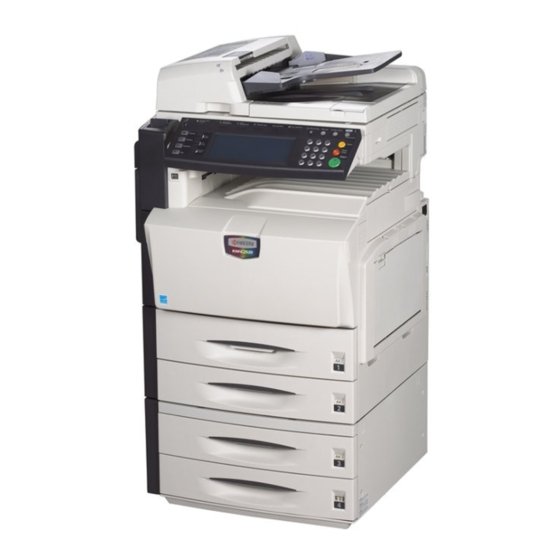
Page 18: Parts Names
2FZ/2F0/2HC-4 1-1-2 Parts names (1) Body 14 15 Figure 1-1-2 Original Platen (Option) 17. Memory Card (CompactFlash) Slot Contact glass 18. Network Interface Connector (Scanner) Original Size Indicator Plates 19. Main Power Switch Operation Panel 20. Main Power Switch Cover MP Tray (multi-purpose tray) 21. - Page 19 2FZ/2F0/2HC (2) Operation panel Figure 1-1-3 Brightness Adjustment Dial 13. Job Build Key/Indicator Copier Key (Indicator/Lamp) 14. Auto Selection Key/Indicator Printer Key (Indicator/Lamp) 15. Job Accounting Key Scanner Key (Indicator/Lamp) 16. Interrupt Key/Indicator Fax Key (Indicator/Lamp) 17. Energy Saver Key/Indicator System Menu/Counter Key 18.
-
Page 20: Machine Cross Section
2FZ/2F0/2HC-3 1-1-3 Machine cross section Figure 1-1-4 Machine cross section Image scanner section 10. Drum section (Yellow) Laser scanner section 11. Drum section (Cyan) Cassette paper feed section 12. Drum section (Magenta) MP tray paper feed section 13. Primary transfer section Developing section (Black) 14. -
Page 21: Installation Environment
2FZ/2F0/2HC-4 1-2 Installation 1-2-1 Installation environment ° ° Temperature: 10 to 32.5 C/50 to 90.5 Humidity: 15 to 80% Power supply: 120 V AC, 12.0 A/220 to 240 V AC, 7.2 A ± ± Power source frequency: 50 Hz 2%/60 Hz Installation location Avoid direct sunlight or bright lighting. -
Page 22: Unpacking And Installation
2FZ/2F0/2HC-4 1-2-2 Unpacking and installation (1) Installation procedure Start Unpacking. Installing the waste toner box. Removing the eject spacer. Loading paper. Release the lever holding Removing the tapes and spacers. the mirror 1 and 2 frames. Installing the optional paper feeder. Installing the original platen or DP (option). - Page 23 2FZ/2F0/2HC Moving the machine When moving the machine, pull out two carrying handles on the left side, and move with carrying handles and the having hand two place of the right side. Figure 1-2-2 1-2-3...
- Page 24 2FZ/2F0/2HC Unpacking. Figure 1-2-3 Unpacking Machine 10. Rear pad Machine cover 11. Manual case Outer case 12. Eject spacer Inner frame 13. Power code Top pad 14. Plastic bag Bottom pad 15. Operation guide Skid 16. M3 x 8 screws Left pad 17.
- Page 25 2FZ/2F0/2HC-4 Removing the eject spacer. 1. Remove the eject spacer and silicagel from the eject section. Silicagel Eject spacer Figure 1-2-4 Removing the tapes and spacers. 1. Remove two tapes. Operation section 2. Remove the spacer from cassette 1. Spacer 3.
- Page 26 2FZ/2F0/2HC Release of lift plate stopper. 1. Pull cassette 1 and 2 out. Remove the lift plate stopper from each cas- Lift plate stopper sette and attach it to the storage location. When moving the machine, attach the lift plate in original position. Figure 1-2-6 2.
- Page 27 2FZ/2F0/2HC-4 4. Install the toner containers. Toner container Figure 1-2-9 5. Press in the toner container upper portion. 6. Turn the toner container lock lever to the left to replenish. Toner container lock lever Figure 1-2-10 Installing the waste toner box. 1.
- Page 28 2FZ/2F0/2HC-4 Loading paper. 1. Pull the cassette out. 2. Adjust the paper length guide to fit the paper size. Support lever 3. Holding the paper width adjusting tab both ends, move the paper width guide to fit the Paper length guide paper.
- Page 29 2FZ/2F0/2HC-4 Release the lever holding the mirror 1 and 2 frames. 1. Turn the lever of the machine rear side with the tool to release the lever holding the mir- ror 1 and 2 frames. Lever Figure 1-2-14 Installing the original platen or DP (option). 1.
- Page 30 2FZ/2F0/2HC-3 Adjusting the image. 1. Open the main power switch cover and turn the main power switch on. 2. Output status report Enter the maintenance mode by entering 10871087 using the numeric keys. Use the numeric keys to enter 000 and press the start key. Select [MAINTENANCE].
- Page 31 2FZ/2F0/2HC (2) Setting initial copy modes Factory settings are as follows: Maintenance Contents Factory setting item No. U253 Switching between double and single counts DOUBLE COUNT (A3/LEDGER) U254 Turning auto start function ON/OFF U260 Selecting the timing for copy counting After ejection U263 Setting the paper ejection...
-
Page 32: Installing The Key Counter (Option)
2FZ/2F0/2HC-6 1-2-3 Installing the key counter (option) Key counter installation requires the following parts: Key counter (P/N 82142540) Key counter set (P/N 302A369708) Key counter mount (P/N 302FZ03010) One (1) M4 × 8 tap-tight S screw (P/N B1A54080) Supplied parts of key counter set: Key counter socket assembly (P/N 3029236241) Key counter cover (P/N 3066060011) Key counter mount (P/N 3066060041) - Page 33 2FZ/2F0/2HC-4 5. Remove the inserted parts and then remove the interface cover. Interface cover Figure 1-2-17 6. Open the front cover. 7. Remove five screws and remove the right cover. Screw Front cover Screw Screw Screw Right cover Screw Figure 1-2-18 8.
- Page 34 2FZ/2F0/2HC-4 9. Remove the upper right cover. 10. Cut out the aperture plate on the upper right cover using nippers. Upper right cover Aperture Figure 1-2-20 11. Attach the key counter mount to the rear M4 x 8 screw upper frame using the M4 x 8 screw. (B1A54080) Key counter mount...
- Page 35 2FZ/2F0/2HC-6 12. Remove the machine’s signal cable from three wire saddles (A). Aperture 13. Fasten the machine’s signal cable to the wire saddle (B). 14. Pass the connector (machine’s signal cable) Connector through the aperture in the upper right cover. 15.
-
Page 36: Installing The Memory (Option)
2FZ/2F0/2HC-4 1-2-4 Installing the memory (option) Procedure 1. Turn the main power switch off and discon- nect the power cord plug from the AC outlet. 2. Open the interface cover. 3. Remove the CF cover. 4. Remove the two screws and then remove the printer PWB. -
Page 37: Installing The Hard Disk (Option)
2FZ/2F0/2HC-4 1-2-5 Installing the hard disk (option) Procedure 1. Turn the main power switch off and discon- nect the power cord plug from the AC outlet. 2. Open the interface cover. 3. Remove the two screws and then remove the slot cover of slot (HDD). 4. -
Page 38: Installing The Network Interface Card (Option)
2FZ/2F0/2HC-4 1-2-6 Installing the network interface card (option) Procedure 1. Turn the main power switch off and discon- nect the power cord plug from the AC outlet. 2. Open the interface cover. 3. Remove the two screws and then remove the slot cover of slot (OPT). -
Page 39: Installing The Serial Interface Board (Option)
2FZ/2F0/2HC-4 1-2-7 Installing the serial interface board (option) Procedure 1. Turn the main power switch off and discon- nect the power cord plug from the AC outlet. 2. Open the interface cover. 3. Remove the CF cover. 4. Remove the two screws and then remove the printer PWB. - Page 40 2FZ/2F0/2HC-4 9. Secure the serial interface board using the two screws. Screw 10. Refit and secure the printer PWB using the two screws. Refit the PWB carefully not to allow its bot- tom come in contact with the three protru- sions on the interface cover.
-
Page 41: Maintenance Mode
2FZ/2F0/2HC 1-3 Maintenance Mode 1-3-1 Maintenance mode The machine is equipped with a maintenance function which can be used to maintain and service the machine. (1) Executing a maintenance item Start Enter 10871087 using Maintenance mode is entered. the numeric keys. Enter the maintenance item number using the cursor up/down keys The maintenance item is... - Page 42 2FZ/2F0/2HC-5 (2) Maintenance mode item list Item Initial Section Content of maintenance item setting* General U000 Printing out an own-status report U001 Exiting the maintenance mode U002 Setting the factory default data U003 Setting the service telephone number *************** *1, *2 U004 Displaying the machine number U019...
- Page 43 2FZ/2F0/2HC-5 Item Initial Section Content of maintenance item setting* High voltage U100 Adjusting main high voltage Adjust MC AC Bias 158/158/158/158 AC Auto Adjustment Adjust DC2 0/0/0/0/0/0/0/0 Low Temp. Setting (Drum) U101 Setting the voltage for the primary transfer 95/75/0/5/10/25 U106 Setting the voltage for the secondary transfer Light/Normal 1 Full Front...
- Page 44 2FZ/2F0/2HC-5 Item Initial Section Content of maintenance item setting* Fuser and U161 Setting the fuser control temperature 160/170/170/170/0/150 *1, *2 cleaning U163 Resetting the fuser problem data U167 Checking/clearing the fuser count U199 Displaying fuser heater temperature Operation U200 Turning all LEDs on panel and U201 Initializing the touch panel...
- Page 45 2FZ/2F0/2HC-5 Item Initial Section Content of maintenance item setting* Image U402 Adjusting margins of image printing 3.0/2.5/2.5/3.0 processing U403 Adjusting margins for scanning an original on the contact 2.0/2.0/2.0/2.0 glass U404 Adjusting margins for scanning an original from the DP 3.0/2.5/3.0/4.0 U407 Adjusting the leading edge registration for memory image...
- Page 46 2FZ/2F0/2HC-5 Item Initial Section Content of maintenance item setting* U925 Checking/clearing the system error counts Other U926 Rewriting FAX program U927 Clearing the all copy counts and machine life counts (one time only) U928 Checking machine life counts U930 Checking/clearing the charger roller count U972 Setting the type of high voltage unit U984...
- Page 47 2FZ/2F0/2HC (3) Contents of maintenance mode items Maintenance Description item No. Printing out an own-status report U000 Description Prints out a list of the current settings of all maintenance items, and occurrences of paper jams and service calls. Also, prints out a list of the toner coverage report (total toner coverage report, copy toner coverage report, printer toner coverage report, fax toner coverage report).
- Page 48 2FZ/2F0/2HC Maintenance Description item No. Setting the service telephone number U003 Description Sets the telephone number to be displayed when a service call code is detected. Purpose To set (during initial set-up of the machine) the telephone number for contacting service. Setting 1.
- Page 49 2FZ/2F0/2HC-4 Maintenance Description item No. Displaying the ROM version U019 Description Displays the part number for the ROM fitted to each PWB. Purpose To check the part number or to decide, if the newest version of ROM is installed. Method 1.
- Page 50 2FZ/2F0/2HC-3 Maintenance Description item No. Memory initializing U021 Description Initializes all settings, except those pertinent to the type of machine, namely each counter, service call history and mode setting. Also initializes backup RAM according to region specification selected in maintenance item U252 Setting the destination.
- Page 51 2FZ/2F0/2HC-5 Maintenance Description item No. Checking switches for paper conveying U031 Description Displays the ON/OFF status of each paper detection switch on the paper conveying path. Purpose To check the operation of the switches for paper conveying. Method 1. Press the start key. A list of switches, the on-off status of which can be checked, are displayed. 2.
- Page 52 2FZ/2F0/2HC-3 Maintenance Description item No. Checking the operation of the solenoids U033 Description Applies current to each solenoid in order to check its ON status. Purpose To check the operation of each solenoid. Method 1. Press the start key. 2. Select the solenoid to be operated. The selected solenoid turns on for 1.5 s. Display Solenoid Branch Inner Tray...
- Page 53 2FZ/2F0/2HC-3 Maintenance Description item No. Adjusting the print start timing U034 Description Adjusts the leading edge registration or center line. Purpose Make the adjustment if there is a regular error between the leading edges of the copy image and original. Make the adjustment if there is a regular error between the center lines of the copy image and original.
- Page 54 2FZ/2F0/2HC-3 Maintenance Description item No. Adjustment: center line adjustment U034 1. Select the item. Display Description Setting Default Change in range setting value per step Center (MPT) Paper feed from MP tray -3.0 to 3.0 0.1 mm Center (Feed 1) Paper feed from cassette 1 -3.0 to 3.0 0.1 mm...
- Page 55 2FZ/2F0/2HC-3 Maintenance Description item No. Checking the operation of the fan motors U037 Description Drives the fan motors. Description To check the operation of the fan motors. Method 1. Press the start key. 2. Select the item to operate. The selected item starts driving the fan motor. Do not drive the paper conveying fan motors 1 to 4 for more than 10 s.
- Page 56 2FZ/2F0/2HC-5 Maintenance Description item No. Adjusting the deflection in the paper U051 Description Adjusts the deflection in the paper at the registration roller. Purpose Make the adjustment if the leading edge of the copy image is missing or varies randomly, or if the copy paper is Z-folded.
- Page 57 2FZ/2F0/2HC-5 Maintenance Description item No. Setting the adjustment of the motor speed U053 Description Performs fine adjustment of the speeds of the motors. After adjustment, run the maintenance item U001 to exit the maintenance mode. And then turn the main power switch off, then on again.
- Page 58 2FZ/2F0/2HC-5 Maintenance Description item No. Adjustment U053 1. Press the interrupt key. 2. Press the start key to output an A3/11" x 17" VTC pattern. Correct values for an A3/11" x 17" output are: ± A = 350 0.5mm ± B = 250 0.5 mm Figure 1-3-4...
- Page 59 2FZ/2F0/2HC-5 Maintenance Description item No. Checking the operation of the exposure lamp U061 Description Lights the exposure lamp. Purpose To check whether the exposure lamp are turned ON. Method 1. Press the start key. 2. Press the start key. The exposure lamp lights. 3.
- Page 60 2FZ/2F0/2HC-5 Maintenance Description item No. Adjustment: main scanning direction U065 1. Press the interrupt key. 2. Place an original and press the start key to make a test copy. 3. Change the setting value using the cursor up/down keys. For copy example 1, increase the value. For copy example 2, decrease the value. Copy Original Copy...
- Page 61 2FZ/2F0/2HC-5 Maintenance Description item No. 3. Press the interrupt key. U066 4. Place an original and press the start key to make a test copy. 5. Change the setting value using the cursor up/down keys. For copy example 1, increase the value. For copy example 2, decrease the value. Scanner leading edge registration Original Copy...
- Page 62 2FZ/2F0/2HC-5 Maintenance Description item No. Caution U067 Check the copy image after the adjustment. If the image is still incorrect, perform the following adjustments in maintenance mode. U403 U072 U404 U067 (P.1-3-72) (P.1-3-25) (P.1-3-73) Completion Press the stop/clear key. The screen for selecting a maintenance item No. is displayed. Adjusting the scanning position for originals from the DP U068 Description...
- Page 63 2FZ/2F0/2HC Maintenance Description item No. Adjusting the DP magnification U070 Description Adjusts the DP original scanning speed. Purpose Make the adjustment if the magnification is incorrect in the auxiliary scanning direction when the optional DP is used. Adjustment 1. Press the start key. Description Setting Initial...
- Page 64 2FZ/2F0/2HC-3 Maintenance Description item No. Adjusting the DP scanning timing U071 Description Adjusts the DP original scanning timing. Purpose Make the adjustment if there is a regular error between the leading or trailing edges of the original and the copy image when the optional DP is used. Adjustment 1.
- Page 65 2FZ/2F0/2HC Maintenance Description item No. Adjusting the DP center line U072 Description Adjusts the scanning start position for the DP original. Purpose Make the adjustment if there is a regular error between the centers of the original and the copy image when the optional DP is used.
- Page 66 2FZ/2F0/2HC Maintenance Description item No. Checking the scanner operation U073 Description Simulates the scanner operation under the arbitrary conditions. Purpose To check the scanner operation. Implementation 1. Press the start key. 2. Select the item to be operated. Display Description SCANNER MOT Scanner operation HOME POSITION...
- Page 67 2FZ/2F0/2HC Maintenance Description item No. Executing DP automatic adjustment U076 Description Uses a specified original and automatically adjusts the following items in the DP scanning section. Adjusting the DP magnification (U070) Adjusting the DP scanning timing (U071) Adjusting the DP center line (U072) When you run this maintenance mode, the preset values of U070, U071 and U072 will also be updated.
- Page 68 2FZ/2F0/2HC-3 Maintenance Description item No. U076 If a problem occurs during auto adjustment, DATA: XX (XX is replaced by an error code) is displayed and operation stops. Should this happen, determine the details of the problem and either repeat the procedure from the beginning, or adjust the remaining items manually by running the corresponding maintenance items.
- Page 69 2FZ/2F0/2HC Maintenance Description item No. Setting DP reading position modification operation U087 Description Sets the black line inspection at the time of reading the original from the DP. Purpose When using optional DP, to solve the problem when black lines occurs due to the dust with respect to original reading position.
- Page 70 2FZ/2F0/2HC Maintenance Description item No. Adjusting the exposure density gradient U093 Description Changes the exposure density gradient in the manual density mode, depending on respective image quality modes. Purpose To set how the image density is altered by a change of one step in the manual density adjustment for respec- tive image quality modes.
- Page 71 2FZ/2F0/2HC Maintenance Description item No. Setting: Gradient in the text in fax mode U093 1. Select the item to be set. 2. Change the setting value using the cursor up/down keys. Setting Default Display Description range setting FAX TEXT DARK Gradient for darker setting 0 to 4 FAX TEXT LIGHT...
- Page 72 2FZ/2F0/2HC Maintenance Description item No. Adjusting original size detection U099 Description Checks the operation of the original size detection sensor and sets the sensing threshold value. Purpose To adjust the sensitiveness of the sensor and size judgement time if the original size detection sensor mal- functions frequently due to incident light or the like.
- Page 73 2FZ/2F0/2HC-5 Maintenance Description item No. Adjusting main high voltage U100 Description Controls the charger roller voltage to optimize the surface potential. Purpose To change the setting value to adjust the image if an image failure (background blur, etc.) occurs. Method 1.
- Page 74 2FZ/2F0/2HC-5 Maintenance Description item No. Setting: Additional surface potential U100 1. Select the item to be set. 2. Change the value using the cursor up/down keys. Setting Default Display Description range setting Bias2K Full Main charger DC bias (black) -128 to 127 Bias2K Half Main charger DC bias (cyan) -128 to 127...
- Page 75 2FZ/2F0/2HC-5 Maintenance Description item No. Setting the voltage for the secondary transfer U106 Description Sets the control voltage for the secondary transfer depending on each paper type. Purpose To change the setting when any density problems, such as too dark or light, occur. Method 1.
- Page 76 2FZ/2F0/2HC-5 Maintenance Description item No. Setting: [Normal 2/3 Full Back] U106 1. Change the value using the cursor up/down keys. Setting Default Display Description range setting Width<160 Small sizes (under 160 mm wide) 0 to 255 255/224* 160<=Width<220 Medium sizes (more than 160 to under 220 mm 0 to 255 240/174* wide)
- Page 77 2FZ/2F0/2HC-5 Maintenance Description item No. Setting the transfer cleaning voltage U107 Description Sets the cleaning control voltage for transfer belt unit. Purpose Change settings if an offset has occurred due to the failure of cleaning the transfer belt. Setting 1. Press the start key. 2.
- Page 78 2FZ/2F0/2HC-5 Maintenance Description item No. Setting separation shift bias U108 Description Adjusts output of separation shift bias and ON/OFF timing. Purpose To set when the separated malfunction of the paper occurs. Start 1. Press the start key. 2. Select the item to be set. The screen for executing each item is displayed. Display Description Set Output Value...
- Page 79 2FZ/2F0/2HC-5 Maintenance Description item No. Checking the drum type U109 Description Displays the drum sensitivity data. Purpose To check the drum sensitivity data. Method 1. Press the start key. 2. Select the item. The drum sensitivity data is displayed. Display Description BLACK (Dark) Drum sensitivity data for black (dark potential)
- Page 80 2FZ/2F0/2HC-5 Maintenance Description item No. Displaying the drum history U118 Description Displays the past record of machine number and the drum counter for each color. Purpose To check the count value of machine number and the drum counter. Method 1. Press the start key. 2.
- Page 81 2FZ/2F0/2HC-5 Maintenance Description item No. Checking the transfer count U127 Description Displays the counts of the transfer counter for checking. Purpose To check the count after replacement of the transfer unit. Method Press the start key. The current counts of the transfer counter is displayed. Completion Press the stop/clear key.
- Page 82 2FZ/2F0/2HC-5 Maintenance Description item No. Adjusting the toner sensor control voltage U131 Description Adjusts the toner sensor control voltage. Purpose If control values are not correctly retrievable due to the EEPROM of the developing unit failure, etc., use man- ual adjustment and obtain a temporary control value. Method 1.
- Page 83 2FZ/2F0/2HC-5 Maintenance Description item No. Replenishing toner forcibly U132 Description Replenishes toner forcibly until the toner sensor output value reaches the toner feed start level. Purpose Used when the toner empty is detected frequently. Method 1. Press the start key. The screen for executing is displayed. 2.
- Page 84 2FZ/2F0/2HC-3 Maintenance Description item No. Setting for toner applying operation U147 Description Sets the mode for removing charged toner in the developing unit (T7 control: Toner applying operation). Purpose Changing settings are not required. However, when the documents with lower print density (e.g. less than 2%) should customarily printed in a great volume, mode must be changed.
- Page 85 2FZ/2F0/2HC-4 Maintenance Description item No. Setting: upper limit printing ratio of toner applying quantity U147 1. Change the setting value using the cursor up/down keys. Description Setting range Default setting Upper limit printing ratio of toner applying quantity with 0 to 10 (%) 5 (%) each mode 2.
- Page 86 2FZ/2F0/2HC-3 Maintenance Description item No. Displaying the toner sensor output U155 Description Displays the toner sensor output value. Purpose To check the output value for each color when any image problems occur. Method 1. Press the start key. 2. Select the item to be set. The setting screen for the selected item is displayed. Display Description Overflow...
- Page 87 2FZ/2F0/2HC-5 Maintenance Description item No. Setting the toner replenishment level U156 Description Sets the toner replenishment level for each color. Purpose To change settings according to the original image. Method 1. Press the start key. 2. Select the item to be set. Display Description Supply Level...
- Page 88 2FZ/2F0/2HC-3 Maintenance Description item No. Checking the developing drive time U157 Description Displays the developing drive time for checking a figure, which is used as a reference when correcting the toner control. Purpose To check the developing drive time after replacing the developing unit. Method Press the start key.
- Page 89 2FZ/2F0/2HC Maintenance Description item No. Checking/clearing the fuser count U167 Description Displays and clears the fuser count for checking. Purpose To check or clear the fuser count after replacement of the fuser unit. Method Press the start key. The fuser count is displayed. Clearing 1.
- Page 90 2FZ/2F0/2HC Maintenance Description item No. Operating the DP separately U203 Description Simulates the original conveying operation separately in the optional DP. Purpose To check the DP operation. Method 1. Press the start key. 2. Place an original in the DP if running this simulation with paper. 3.
- Page 91 2FZ/2F0/2HC-5 Maintenance Description item No. Setting the paper size for the paper feeder U208 Description Sets the size of paper used in optional 3000-sheet paper feeder. Purpose To change the setting when installing the optional 3000-sheet paper feeder or the size of paper used in the paper feeder is changed.
- Page 92 2FZ/2F0/2HC Maintenance Description item No. Setting finisher stack quantity U237 Description Sets the number of sheets of each stack on the main tray and on the internal tray in optional 3000-sheet doc- ument finisher. Purpose To change the setting when a stack malfunction has occurred. Method 1.
- Page 93 2FZ/2F0/2HC-4 Maintenance Description item No. Checking the operation of the finisher U240 Description Turns each motor and solenoid of optional 3000-sheet document finisher ON. Purpose To check the operation of each motor and solenoid of the document finisher. Method 1. Press the start key. 2.
- Page 94 2FZ/2F0/2HC-4 Maintenance Description item No. Method: Checking the solenoid of the document finisher U240 1. Select the item to be operated. Display Solenoid CARRY SOL Paper entry solenoid (PESOL) REAR DOWN1 Trailing edge holder solenoid 1 (TEHSOL1) REAR DOWN2 Trailing edge holder solenoid 2 (TEHSOL2) SUBPATH SOL Relief path solenoid (RPSOL) SUB T R SOL...
- Page 95 2FZ/2F0/2HC-4 Maintenance Description item No. Checking the operation of the switches of the finisher U241 Description Displays the status of each switch of optional 3000-sheet document finisher. Purpose To check the operation of each switch of the document finisher. Method 1.
- Page 96 2FZ/2F0/2HC-4 Maintenance Description item No. Method: Checking the switch of the mailbox U241 1. Turn each switch on and off manually to check the status. When the on-status of a switch is detected, that switch is displayed in reverse. Display Switches CARRY Mail paper entry switch (MPESW)
- Page 97 2FZ/2F0/2HC-5 Maintenance Description item No. Checking the operation of the DP motors U243 Description Turns the motors, solenoids or clutch in the document processor on. Purpose To check the operation of the document processor motors, solenoids and clutch. Method 1. Press the start key. 2.
- Page 98 2FZ/2F0/2HC-5 Maintenance Description item No. Checking messages U245 Description Displays a list of messages on the touch panel of the operation panel. Purpose To check the messages to be displayed. Method 1. Press the start key. 2. Select the item to be displayed. 3.
- Page 99 2FZ/2F0/2HC-3 Maintenance Description item No. Setting the paper ejection device U246 Description Provides various settings for the optional finisher, if furnished. Purpose Adjustment of registration stop timing in punch mode Adjust if skewed paper conveying occurs or if the copy paper is Z-folded in punch mode. Adjustment of paper stop timing in the punch mode To adjust this item when the position of a punch hole is different from the specified one.
- Page 100 2FZ/2F0/2HC-3 Maintenance Description item No. Setting: adjustment of the paper stop timing U246 1. Select [PUNCH POS ADJ]. 2. Change the setting value using the cursor up/down keys. Setting Default Change in Description range setting value per step Adjustment of the paper stop timing -10 to 10 0.24 mm If the distance of the position of a punch hole is smaller than the specified value A, increase the preset...
- Page 101 2FZ/2F0/2HC-5 Maintenance Description item No. Setting: adjustment of slanted stapling home position U246 1. Select [T-STAPLE HP ADJ]. 2. Change the setting value using the cursor up/down keys. Setting Default Change in Description range setting value per step ° Adjustment of slanted stapling home position -10 to 10 To increase the angle for slanted stapling (sample 1), decrease the preset value.
- Page 102 2FZ/2F0/2HC-5 Maintenance Description item No. Setting: adjustment of booklet stapling position U246 1. Select [STAPLE POS ADJ1], [STAPLE POS ADJ2] or [STAPLE POS ADJ3]. 2. Change the setting value using the cursor up/down keys. Setting Default Change in Description range setting value per step Adjustment of booklet stapling position for A4/8.5 x 11...
- Page 103 2FZ/2F0/2HC-4 Maintenance Description item No. Setting the paper feed device U247 Description Turns on motor and clutches of optional 3000-sheet paper feeder or paper feeder. Purpose To check the operation of motor and clutches of paper feed device. Method 1. Press the start key. The value varies depending to the option furnished. 3000-sheet paper feeder.
- Page 104 2FZ/2F0/2HC-3 Maintenance Description item No. Checking/clearing the maintenance count U251 Description Displays and clears or changes the maintenance count and automatic grayscale adjustment count. Purpose To verify the maintenance counter count and automatic grayscale count. Also to clear the count during main- tenance service.
- Page 105 2FZ/2F0/2HC-5 Maintenance Description item No. Switching between double and single counts U253 Description Switches the count system for the total counter and other counters for every color mode. Purpose Used to select, according to the preference of the user (copy service provider), if A3/11" x 17" paper is to be counted as one sheet (single count) or two sheets (double count).
- Page 106 2FZ/2F0/2HC-3 Maintenance Description item No. Selecting the timing for copy counting U260 Description Changes the copy count timing for the total counter and other counters. Purpose To be set according to user (copy service provider) request. If a paper jam occurs frequently in the optional finisher when the number of copies is counted at the time of paper ejection, copies are provided without copy counts.
- Page 107 2FZ/2F0/2HC Maintenance Description item No. Setting the display order of the date U264 Description Selects year, month and day as the order of that appears on lists, etc. Purpose Set according to the user preference. Setting 1. Press the start key. 2.
- Page 108 2FZ/2F0/2HC Maintenance Description item No. Setting auto application change time U277 Description Sets the time that passes until the machine starts automatically printing after completing copying or operation when the machine is used as a printer. Purpose According to user request, changes the setting. Setting 1.
- Page 109 2FZ/2F0/2HC-3 Maintenance Description item No. Setting the bias between pages U325 Description Determines the distance between two pages when printing pages of high print coverage. Purpose To change the setting when pages are not printed continuously due to an intermittent toner replenishing that may happen when attempting to print a highly dense document.
- Page 110 2FZ/2F0/2HC-3 Maintenance Description item No. Setting the cassette heater ON/OFF U327 Description Sets ON/OFF of the cassette heater. Purpose To change the setting when dew condensation on the drum is heavy. Setting 1. Press the start key. 2. Select ON or OFF. Display Description Cassette heater ON...
- Page 111 2FZ/2F0/2HC-3 Maintenance Description item No. Switching between duplex/simplex copy mode U343 Description Switches the initial setting between duplex and simplex copy. Purpose To be set according to frequency of use: set to the more frequently used mode. Setting 1. Press the start key. 2.
- Page 112 2FZ/2F0/2HC-3 Maintenance Description item No. U402 3. Press the interrupt key. 4. Press the start key to output a test pattern. 5. Change the setting value using the cursor up/down keys. Increasing the value makes the margin wider, and decreasing it makes the margin narrower. Printer leading edge margin (3.0+0.5mm) Ejection direction...
- Page 113 2FZ/2F0/2HC-3 Maintenance Description item No. U403 5. Change the setting value using the cursor up/down keys. Increasing the value makes the margin wider, and decreasing it makes the margin narrower. Scanner leading edge margin (3.5±0.5mm) Ejection direction (reference) Scanner Scanner left margin right margin (2.0±1.0mm)
- Page 114 2FZ/2F0/2HC-3 Maintenance Description item No. U404 5. Change the setting value using the cursor up/down keys. Increasing the value makes the margin wider, and decreasing it makes the margin narrower. Leading edge margin (3.5±0.5mm) Ejection direction (reference) Left margin Right margin (2.0±1.0mm) (2.0±1.0mm) Trailing edge margin...
- Page 115 2FZ/2F0/2HC-3 Maintenance Description item No. Completion U407 Press the stop/clear key. The screen for selecting a maintenance item No. is displayed. Adjusting the halftone automatically U410 Description Carries out processing for the data acquisition that is required in order to perform either automatic adjustment of the halftone or the ID correction operation.
- Page 116 2FZ/2F0/2HC Maintenance Description item No. Setting the target U425 Description The value that is indicated on the back of the chart (P/N: 302FZ56990) to be used for adjustment should be entered. Purpose Performs data input in order to correct for differences in originals during automatic adjustment. Method 1.
- Page 117 2FZ/2F0/2HC Maintenance Description item No. Setting the offset for the color balance U429 Description Displays and changes the density for each color during copying in the various image quality modes. Purpose To change the balance for each color. Start 1. Press the start key. 2.
- Page 118 2FZ/2F0/2HC Maintenance Description item No. Setting the center offset for the exposure U432 Description Sets the offset value for the setting data for exposure centering adjustment under user simulation. For exam- ple, if the value for the exposure centering adjustment is set to -1 and you change the offset value to +2, image processing is performed as though the exposure centering adjustment setting is +1.
- Page 119 2FZ/2F0/2HC-3 Maintenance Description item No. Setting the ID correction operation U464 Description Turns ID correction on or off. Also, this determines the duration of ID correction and the timing of ID correction during printing. Purpose To restrict ID correction when poor image quality is generated. Start 1.
- Page 120 2FZ/2F0/2HC-3 Maintenance Description item No. Data reference for ID correction U465 Description References the data related to ID correction. Purpose To check the corresponding data. Method 1. Press the start key. 1. Select the item to be reference. The current setting is displayed. Display Description TCONT...
- Page 121 2FZ/2F0/2HC Maintenance Description item No. Checking the color registration data U468 Description Displays the color registration correction data and transfer belt speed correction data. Purpose To check the corresponding data. Start 1. Press the start key. 2. Select the item to check. Display Description Auto Adjustment...
- Page 122 2FZ/2F0/2HC-3 Maintenance Description item No. Setting the compression ratio U470 Description Sets the compression ratio coefficient for each compression level based on the quantum chart for JPEG brightness and color differential. Purpose To change the setting in accordance with the image that the user is copying. For example, in order to soften the coarseness of the image when making copies at over 200% magnification, change the level of compres- sion by raising the value.
- Page 123 2FZ/2F0/2HC-5 Maintenance Description item No. Adjusting laser power output U473 Description Adjusts the laser output power for each color. Also, this is used to toggle exposure density correction and enter exposure density correction values. Purpose Enter the exposure density correction data after replacing the laser scanner unit. Also performed when the quality of dots, lines or low density has dropped.
- Page 124 2FZ/2F0/2HC Maintenance Description item No. Checking LSU cleaning operation U474 Description Provides cleaning LSU by means of the LSU cleaning clutch and LSU cleaning solenoid. Also, the cleaning cycle can be adjusted. Start 1. Press the start key. 2. Select the item. Display Description Cleaning Operation...
- Page 125 2FZ/2F0/2HC Maintenance Description item No. Setting the time out U506 Description Sets the communication timeout time for connection to a computer. Purpose To change the preset value if a communication error occurs after connection to a computer continues for a long time.
- Page 126 2FZ/2F0/2HC-5 Maintenance Description item No. Setting scan To FTP U511 Description Sets whether or not scan to FTP setting is enabled. This maintenance mode is effective for only 120 V specifications. Purpose According to user request, changes the setting. Supplement It is not possible to turn setting simultaneously with U510 (Setting the enterprise mode) to ON.
- Page 127 2FZ/2F0/2HC Maintenance Description item No. Checking/clearing finisher punch count U902 Description Sets the punch limit and displays and clears the punch-hole scrap count when optional 3000-sheet finisher is installed. Purpose Sets the punch limit to notify the user of the time to collect punch-hole scrap. Also, used to manually clear the punch-hole scrap count if a message requiring collection of punch-hole scrap is shown on the touch panel after collection.
- Page 128 2FZ/2F0/2HC Maintenance Description item No. Checking/clearing the call for service counts U904 Description Displays or clears the service call code counts by types. Purpose To check the service call code status by types. Also to clear the service call code counts after replacing consumable parts. Start Press the start key.
- Page 129 2FZ/2F0/2HC-4 Maintenance Description item No. Resetting partial operation control U906 Description Resets the service call code for partial operation control. Purpose To be reset after partial operation is performed due to problems in the cassettes or other sections, and the related parts are serviced.
- Page 130 2FZ/2F0/2HC-3 Maintenance Description item No. Setting backup data reading/writing U917 Description Stores backup data from the fax control PWB (when an optional fax kit is installed) into CompactFlash or reads the data from CompactFlash. Purpose To store and write data when replacing the PWB. Setting 1.
- Page 131 2FZ/2F0/2HC-5 Maintenance Description item No. Checking the copy counts U920 Description Checks the copy counts. Purpose To check the copy counts. Method Press the start key. The current counts of full color copy counter, single color copy counter, monochrome copy counter, color printer counter, monochrome printer counter and monochrome fax counter are displayed.
- Page 132 2FZ/2F0/2HC-5 Maintenance Description item No. U926 If the operation was successful: EXECUTE 0100 CHECK SUM **** CODE 0000 If the operation failed: EXECUTE 0100 CHECK SUM **** CODE XXXX Where XXX is the error code indicating the reason for the failure. See Error Codes for Operation U917 and U926 on P.1-3-90.
- Page 133 2FZ/2F0/2HC-5 Maintenance Description item No. Setting the type of high voltage unit U972 Description Identifies transfer high voltage PWB 2 to be old or new Purpose To change the setting when replacing the transfer high voltage PWB 2. Setting 1. Press the start key. 2.
- Page 134 2FZ/2F0/2HC Maintenance Description item No. Checking/clearing the time for the exposure lamp to light U990 Description Displays, clears or changes the accumulated time for the exposure lamp to light. Purpose To check duration of use of the exposure lamp. Also to clear the accumulated time for the lamp after replace- ment.
-
Page 135: Service Mode
2FZ/2F0/2HC-6 1-3-2 Service mode The machine is equipped with a maintenance function which can be used to maintain and service the machine. (1) Executing a service item Start Press the print key. Press [Printer Menu]. Press [Others]. Press [Service]. To print a status page for Press [Print Status Page]. -
Page 136: Service Information
2FZ/2F0/2HC Service items Description Printing a status page for service purpose Description Prints a status page for service purpose. The status page includes various printing settings Print and service cumulative. Status Page Purpose To acquire the current printing environmental parameters and cumulative information. Procedure Select [Print Status Page]. - Page 137 2FZ/2F0/2HC Service items Description Service information Service information [XXXXXXXXXXXXXXXX][XX/XX] Printed Page(s) 9690 /P00/S00/U00/N00/D50:DM0301.DAN:0002001001210052 /0020/0020/1061/0811/ 0/ 0/ 0/ 0/ 0/ 0/ 0/ /1011/1001/0000/0000/0100/1000/0000/0000/ /RS2/[0003-0003]/81/30/50/01 00.00.00.00.00.00 A:1234567890123456 /20A11080/1020B200/20001080/81000000/00000000/10101010/10101010/ SPD1:0203040508090A0B0C0D0F101112131415161718191A1B1C1D1E1F202122235E SPD1:0203040508090A0B0C0D0F101112131415161718191A1B1C1D1E1F202122235E SN:SPL9200010 1-3-97...
- Page 138 [First byte/second byte (dis- bit 2, 3 (Not used) played in OEM mode only)] bit 4 = 0: Kyocera, 1: OEM bit 5 = 0: For Europe, 1: For US bit 6 = 0: Non MICR mode, 1: MICR mode...
- Page 139 2FZ/2F0/2HC Service items Description Items Description Serial interface information RS2: RS-232C RS4: RS-422A Optional device information 1st 2 bytes 2nd 2 bytes bit0: MP tray bit0: Reserved bit1 to 2: Cassette 1 to 2 bit1: Output tray bit3 to 4: Optional cassette 3 to 4 bit2 to 3: Reserved bit5 to 6: Not used bit4: Optional finisher...
- Page 140 2FZ/2F0/2HC-6 Service items Description Setting the paper feed operation (printer driver yielding mode) Description Paper Feed In printer driver yielding mode, the printer driver settings override the paper feed operation Operation mode in the machine. The machine feeds paper from the paper source (a cassette or the MP tray) which was com- manded by the printer driver, and if the paper source is empty, the machine will prompt load- ing paper by displaying a message.
-
Page 141: Copier Management
2FZ/2F0/2HC 1-3-3 Copier management In addition to a maintenance function for service, the copier is equipped with a management function which can be oper- ated by users (mainly by the copier administrator). In this copier management mode, settings such as default settings can be changed. - Page 142 2FZ/2F0/2HC (2) Job accounting Management total Calculate the total usage count for all departments and New account print the total in the form of Job Accounting reports. The Creates new accounts by entering an account ID code (of total usage count can be reset as necessary. up to eight digits), account name, and restrictions on 1.
- Page 143 2FZ/2F0/2HC Printer error report Response to unauthorized requests Specify whether an error report is printed in case that the Specify the actions when users attempt to copy in excess user attempts to print using the incorrect department of the specified copy limitation. code.
- Page 144 2FZ/2F0/2HC (3) Default settings for copying Select paper In default settings mode, set the paper selection method Exposure Mode for when an original is set. Set the exposure mode for default settings mode. 1. Select [Select Paper] using the cursor up/down 1.
- Page 145 2FZ/2F0/2HC Setting auto % priority Erasing borders Specify whether to set auto zoom when the paper in the Set the border erase default values. selected cassette is different from the size of the original. 1. Select [Default erase width] using the cursor up/ 1.
- Page 146 2FZ/2F0/2HC (4) Machine default 5. To specify a paper type, press [Select Paper Type]. Select the paper type and press [Close]. Enabling auto cassette switching Plain/Transparency/Rough/Vellum/Labels/Recy- Use auto cassette switching to automatically switch the cled/Preprinted/Bond/Cardstock/Color (Colour)/ paper source to another cassette loaded with the same Prepunched/Letterhead/Thick paper/Envelope/ size and orientation paper when the current cassette runs Coated/High Quality/Custom 1 - 8...
- Page 147 2FZ/2F0/2HC Auto detect originals Selecting output destination Specify the paper size to select when an original with a Set the default copy output destination. similar size is automatically detected. This setting is displayed when the optional job separator, This setting is displayed only for metric models. document finisher or 3000 sheet document finisher is 1.
- Page 148 2FZ/2F0/2HC Setting time difference Erasing hard disk contents Set the time difference. When the optional security kit is installed, select the hard Set the time difference before Adjusting Date/Time. disk overwrite method. 1. Select [Time difference] using the cursor up/down This setting is available when optional security kit is keys and press [Change #].
- Page 149 2FZ/2F0/2HC (5) Printer settings 10. Enter the IP address using the numeric keys. Input the address for the 3 digits displayed in reverse Print Status Page black and white and press the [#] key. Print a status page to check details such as current set- 11.
- Page 150 2FZ/2F0/2HC Emulation mode selection Font selection Change the emulation mode. Select the default font. 1. Press [Emulation]. 1. Press [Font]. 2. Press the interface to be configured. 2. Press [Font selection]. 3. Select the desired emulation. 3. Press the interface to be configured. PCL6/KPDL/KPDL (Auto) /KC-GL 4.
- Page 151 2FZ/2F0/2HC Print list of fonts CR (carriage return) action Print a list of fonts for use as a quick guide during font Set the action to be performed by the device when a car- selection. riage return code (text code 0DH) is received. 1.
- Page 152 2FZ/2F0/2HC Paper output select Deleting data Set the output destination for printed paper. If the optional Delete data, program data, fonts, macro data or option document finisher or 3000 sheet document finisher, or languages saved to a memory card. mailbox is installed, you can specify each tray. 1.
- Page 153 2FZ/2F0/2HC RAM disk size setting Setting resource protect mode Specify the amount of memory from this device total When this device's emulation switches from PCL 6 to memory to allocate to the RAM disk. Enabling this func- another emulation type, all downloaded fonts and macros tion allows the use of electronic sorting and decreasing are lost.
- Page 154 2FZ/2F0/2HC Service settings (6) Scanner default settings Use to print a service status page for reference during Original Density maintenance or service. Set the image quality for default settings mode. 1. Press [Others]. 1. Select [Original density] using the cursor up/down 2.
- Page 155 2FZ/2F0/2HC Batch scanning Color mode setting Configure batch scanning for default settings mode. Set the color mode for default settings mode. 1. Select [Batch Scanning] using the cursor up/down 1. Select [Color setting] ([Colour setting]) using the keys and press [Change #]. cursor up/down keys and press [Change #].
- Page 156 2FZ/2F0/2HC (8) Setting MP tray (9) Registering non-standard sizes for originals Specifying the paper size to the MP tray Pre-register 4 types of non-standard original sizes. 1. Select the number to register from [Original Size Auto detect (custom 1 - 4)] and press [Change #]. The paper size is automatically detected.
- Page 157 2FZ/2F0/2HC (10) User adjustment Color registration Use this function to correct the color position of each of Color calibration cyan, magenta and yellow to resolve color drift. Using this function enables printing in the most appropri- Normal registration and detailed settings are available for ate color by adjusting hue and color drift in detail.
- Page 158 2FZ/2F0/2HC 8. Press [Next] to continue entering the values for C 8. Press [+] or [-] to enter the value for H-1 from the (cyan) and Y (yellow). chart for each of M (magenta), C (cyan) and Y (yel- Press [Back] to return to the previous screen and low).
- Page 159 2FZ/2F0/2HC (11) Setting document management defaults Specifying period to store documents Set to delete documents from a Synergy Print Box after Print document list storing them for a predefined period. Print the Document list for the Shared Data Box and Syn- 1.
- Page 160 2FZ/2F0/2HC (15) Language Select the language displayed on the touch panel. 1. Select the key for the language you would like to set. Inch models: English/French/Spanish/Japanese/ Portuguese Metric models: English/German/French/Spanish/ Italian 2. The touch panel display will change to that lan- guage.
-
Page 161: Paper Misfeed Detection
2FZ/2F0/2HC-4 1-4 Troubleshooting 1-4-1 Paper misfeed detection (1) Paper misfeed indication When a paper misfeed occurs, the machine immediately stops copying and displays the jam location on the operation panel. Paper misfeed counts sorted by the detection condition can be checked in maintenance item U903. To remove paper jammed in the machine, open the left cover, paper conveying unit, fuser cover, pull the cassette out or pull the MP conveying unit out. - Page 162 2FZ/2F0/2HC-3 (2) Paper misfeed detection conditions FSSW DUJDSW PCCL FSW1 MPPFCL MPPCSW PFCL1 MPPFSW MPPCCL FSW2 PFCL2 FSW3 Figure 1-4-2 1-4-2...
- Page 163 2FZ/2F0/2HC-5 Section Jam code Conditions Specified time Paper feed Feed switch 1 (FSW1) does not turn on within the specified 1690 ms section No paper feed from cas- time of paper feed clutch 1 (PFCL1) turning on; the clutch is sette 1 then successively turned off for 1 s and turned back on, but the switch again fails to turn on within the specified time.
- Page 164 2FZ/2F0/2HC-5 Section Jam code Conditions Specified time Paper feed Feed switch 1 (FSW1) does not turn off within specified time of 1026 ms section Misfeed in vertical paper feed switch 2 (FSW2) turning on. conveying section Feed switch 2 (FSW2) does not turn off within specified time of 1118 ms feed switch 3 (FSW3) turning on.
- Page 165 2FZ/2F0/2HC-5 Section Jam code Conditions Specified time Paper con- Cover is open during paper conveying. veying sec- Cover open tion Secondary paper feed does not start even if 45 s elapse after 40 s Memory read ready time- the registration switch (RSW) is turned on and primary paper feed is complete.
- Page 166 2FZ/2F0/2HC-5 Section Jam code Conditions Specified time Duplex The duplex jam detection switch (DUJDSW) does not turn on 3006 ms section Duplex paper conveying within specified time of the feedshift switch (FSSW) turning on. section 1 The duplex jam detection switch (DUJDSW) does not turn off 3006 ms within specified time of the feedshift switch (FSSW) turning off.
- Page 167 2FZ/2F0/2HC-5 Section Jam code Conditions Specified time Optional (3000-sheet document finisher) 1592 ms finisher Paper entry sensor non The paper entry sensor (PES) is not turned off even if a speci- arrival jam fied time has elapsed after the machine eject signal was received.
- Page 168 2FZ/2F0/2HC-5 Section Jam code Conditions Specified time Optional Internal tray entry sensor 2 (ITPES2) does not turn on within 4059 ms finisher Jam in eject section of specified time of the paper entry sensor (PES) turning on. internal tray 2 (3000-sheet Internal tray entry sensor 2 (ITPES2) does not turn off within 1371 ms document finisher only)
- Page 169 2FZ/2F0/2HC-5 Section Jam code Conditions Specified time Optional (3000-sheet document finisher) finisher Finisher cover open The front cover, top cover or right sub tray is opened when starting the finisher operation. The centerfold unit top cover is opened when starting the cen- terfold operation.
- Page 170 2FZ/2F0/2HC (3) Paper misfeeds Problem Causes/check procedures Corrective measures A piece of paper torn from Check visually and remove it, if any. A paper jam in the copy paper is caught paper feed, convey- around feed switches, MP ing, duplex or eject paper feed switch, MP section is indicated paper conveying switch,...
- Page 171 2FZ/2F0/2HC-4 Problem Causes/check procedures Corrective measures Optional paper feeder A paper jam in the Paper is extremely curled. Change the paper. paper feed section is indicated during Check if the paper feed pul- Check visually and replace any deformed pulleys. copying (no paper ley, forwarding pulley and feed from optional...
- Page 172 2FZ/2F0/2HC Problem Causes/check procedures Corrective measures Paper is extremely curled. Change the paper. A paper jam in the Check if the MP paper feed Check visually and replace any deformed pulleys. paper feed section is pulley, MP forwarding pulley indicated during and MP separation pulley copying (no paper are deformed.
- Page 173 2FZ/2F0/2HC Problem Causes/check procedures Corrective measures Check if the paper side Check visually and replace. A paper jam in the guides are deformed. paper feed section is Defective paper path sen- With 5 V DC present at CN6-6 on the paper feeder main PWB, indicated during sor 1.
- Page 174 2FZ/2F0/2HC-4 Problem Causes/check procedures Corrective measures (13) Broken feed switch 1 actua- Check visually and replace switch. A paper jam in the tor. paper feed section is Defective feed switch 1. Run maintenance item U031 and turn feed switch 1 on and off indicated during manually.
- Page 175 2FZ/2F0/2HC-3 Problem Causes/check procedures Corrective measures (17) Broken switch actuator. Check visually and replace switch. A paper jam in the Defective switch. Run maintenance item U031 and turn the following switch on and paper feed section is off manually. Replace the switch if indication of the corresponding indicated during switch on the touch panel is not displayed in reverse.
- Page 176 2FZ/2F0/2HC Problem Causes/check procedures Corrective measures (22) Broken switch actuator. Check visually and replace switch. A paper jam in the Defective switch. Run maintenance item U031 and turn the following switch on and eject section is indi- off manually. Replace the switch if indication of the corresponding cated during copying switch on the touch panel is not displayed in reverse.
- Page 177 2FZ/2F0/2HC-3 Problem Causes/check procedures Corrective measures (28) Defective switch. Run maintenance item U244 and turn the following switch on and off manually. Replace the switch if indication of the corresponding An original jams in switch on the touch panel is not displayed in reverse. optional DP is indi- DP timing switch, original feed switch, original switchback switch cated during copying...
- Page 178 2FZ/2F0/2HC-3 Problem Causes/check procedures Corrective measures (34) Extremely curled paper. Change the paper. A paper jam in Defective paper entry sen- (3000-sheet document finisher) optional document sor. Run maintenance item U241 and turn the paper entry sensor on finisher is indicated and off manually.
- Page 179 2FZ/2F0/2HC-4 Problem Causes/check procedures Corrective measures (39) Defective internal tray Run maintenance item U241 and turn internal tray paper entry A paper jam in paper entry sensor 2. sensor 2 on and off manually. Replace the switch if indication of optional document the corresponding switch on the touch panel is not displayed in finisher is indicated...
- Page 180 2FZ/2F0/2HC-4 Problem Causes/check procedures Corrective measures (44) Defective reverse sensor. With 5 V DC present at CN14-5 on the finisher main PWB, check A paper jam in if CN14-7 on the finisher main PWB remains low or high when the optional document reverse sensor is turned on and off.
- Page 181 2FZ/2F0/2HC-3 1-4-2 Self-diagnosis (1) Self-diagnostic function This unit is equipped with a self-diagnostic function. When a problem is detected, copying is disabled and the problem dis- played as a code consisting of C followed by a number, indicating the nature of the problem. A message is also displayed requesting the user to call for service.
- Page 182 2FZ/2F0/2HC-6 Partial operation control If one of the following service codes is detected, partial operation control will be activated. Take actions to clear the cause of the trouble and perform maintenance item U906 to reset partial operation control. Code Contents C0840 Faults of RTC C1010...
- Page 183 2FZ/2F0/2HC-3 (2) Self diagnostic codes Remarks Code Contents Causes Check procedures/corrective measures C0030 Fax control PWB system problem Defective fax con- Replace the fax control PWB and verify the (optional fax) trol PWB. operation. Processing with the fax software was disabled due to a hardware or software problem.
- Page 184 2FZ/2F0/2HC-3 Remarks Code Contents Causes Check procedures/corrective measures C0240 Printer PWB communication problem Poor contact in the Check the connection of connector YC21 on The printer PWB does not respond 120 s connector termi- the engine PWB and the connector YC7 on after the power is turned on.
- Page 185 2FZ/2F0/2HC-3 Remarks Code Contents Causes Check procedures/corrective measures C0440 Document finisher communication Poor contact in the Check the connection of connector YC33 on problem (optional document finisher) connector termi- the engine PWB and the connector on the A communication error from document nals.
- Page 186 2FZ/2F0/2HC-3 Remarks Code Contents Causes Check procedures/corrective measures C0870 Fax control PWB to main PWB high Poor contact in the Check the connection of connector YC6 on capacity data transfer problem connector termi- the main PWB and the connector on the fax High-capacity data transfer between the nals.
- Page 187 2FZ/2F0/2HC-3 Remarks Code Contents Causes Check procedures/corrective measures C1020 Lift motor 2 error Poor contact in the Check the connection of connector of lift When cassette 2 is inserted, lift limit connector termi- motor 2 and the connector YC25 on the switch 2 does not turn on within 12 s of nals.
- Page 188 2FZ/2F0/2HC-3 Remarks Code Contents Causes Check procedures/corrective measures C1100 Paper feeder lift motor 1 error Poor contact in the Check the connection of connector on the (optional 3000-sheet paper feeder) connector termi- engine PWB and the connector on the paper A motor over-current signal is detected nals.
- Page 189 2FZ/2F0/2HC-3 Remarks Code Contents Causes Check procedures/corrective measures C1900 Paper feeder EEPROM error (optional Poor contact in the Check the connection of connector on the paper feeder) connector termi- engine PWB and the connector on the paper When writing the data, the write data and nals.
- Page 190 2FZ/2F0/2HC-3 Remarks Code Contents Causes Check procedures/corrective measures C2102 Developing motor CMY error Poor contact in the Check the connection of connector YC26 on After the motor drive ON signal is output connector termi- the engine PWB and the connector on the and 1 s elapses, the rated speed reach nals.
- Page 191 2FZ/2F0/2HC-3 Remarks Code Contents Causes Check procedures/corrective measures C2203 Drum motor M error Poor contact in the Check the connection of connector YC1 on After the motor drive ON signal is output connector termi- the motor relay PWB and the connector on and 1 s elapses, the rated speed reach nals.
- Page 192 2FZ/2F0/2HC-3 Remarks Code Contents Causes Check procedures/corrective measures C2400 Eject motor error Poor contact in the Check the connection of connector YC27 on After the motor drive ON signal is output connector termi- the engine PWB and the connector on the and 1 s elapses, the rated speed reach nals.
- Page 193 2FZ/2F0/2HC-3 Remarks Code Contents Causes Check procedures/corrective measures C2810 Waste toner motor error Poor contact in the Check the connection of connector YC30 on The rated speed achievement signal connector termi- the engine PWB and the connector on the won’t turn to L in 5 s since the motor is nals.
- Page 194 2FZ/2F0/2HC-3 Remarks Code Contents Causes Check procedures/corrective measures C3300 Optical system (AGC) problem Poor contact in the Check the connection of connector YC6 on After AGC, correct input is not obtained connector termi- the scanner PWB and the connector on the at CCD.
- Page 195 2FZ/2F0/2HC-5 Remarks Code Contents Causes Check procedures/corrective measures C4200 BD steady-state problem Poor contact in the Check the connection of connector YC16 on ASIC of the engine PWB detects a BD connector termi- the engine PWB and laser scanner unit, and error for 200 ms after the polygon motor nals.
- Page 196 2FZ/2F0/2HC-5 Remarks Code Contents Causes Check procedures/corrective measures C5303 Cleaning lamp M break error Poor contact in the Check the connection of connector YC17 on After the cleaning lamp M ON signal is connector termi- the engine PWB and the connector on the turned on, the cleaning lamp M break nals.
- Page 197 2FZ/2F0/2HC-4 Remarks Code Contents Causes Check procedures/corrective measures C6100 Fuser heater 3 break Defective fuser Check for continuity across each heater. If Fuser thermistor 2 detected less than heater 3. none, replace the fuser unit (see page 1-5- ° ° 31).
- Page 198 2FZ/2F0/2HC-3 Remarks Code Contents Causes Check procedures/corrective measures C7103 Toner sensor M problem Defective develop- Replace the developing unit M (see page 1- Sensor output value of 78 or less or 944 ing unit M. 5-26). or more continued for 3 s. Defective engine Replace the engine PWB and check for cor- PWB.
- Page 199 2FZ/2F0/2HC-5 Remarks Code Contents Causes Check procedures/corrective measures C7401 Developing unit BK type mismatch Developing unit Reinsert the developing unit connector if problem connector inserted necessary. Absence of the developing unit BK is incorrectly. detected. Different type of Install the correct developing unit. the developing unit is installed.
- Page 200 2FZ/2F0/2HC-5 Remarks Code Contents Causes Check procedures/corrective measures C7420 Transfer belt unit type mismatch Transfer belt unit Reinsert the transfer belt unit connector if problem connector inserted necessary. Absence of the transfer belt unit is incorrectly. detected. Different type of Install the correct transfer belt unit.
- Page 201 2FZ/2F0/2HC-5 Remarks Code Contents Causes Check procedures/corrective measures C7912 Developing unit C EEPROM error Poor contact in the Check the connection of connector YC17 on Reading from or writing to EEPROM connector termi- the engine PWB and the continuity across cannot be performed.
- Page 202 2FZ/2F0/2HC-5 Remarks Code Contents Causes Check procedures/corrective measures C8050 Paper conveying belt motor 1 prob- Poor contact in the Check the connection of connector YC2 on lem (optional 3000-sheet document connector termi- the internal tray PWB and the connector on finisher) nals.
- Page 203 2FZ/2F0/2HC-5 Remarks Code Contents Causes Check procedures/corrective measures C8140 Main tray problem (optional 3000- Poor contact in the Check the connection of connector YC6 on sheet document finisher) connector termi- the finisher main PWB and the connector on The main tray is not detected by the nals.
- Page 204 2FZ/2F0/2HC-5 Remarks Code Contents Causes Check procedures/corrective measures C8170 Side registration motor 1 problem Poor contact in the Check the connection of connector YC2 on (optional 3000-sheet document fin- connector termi- the internal tray PWB and the connector on isher) nals.
- Page 205 2FZ/2F0/2HC-5 Remarks Code Contents Causes Check procedures/corrective measures C8210 Stapler shift motor 1 error (optional Poor contact in the Check the connection of connector YC9 on 3000-sheet document finisher) connector termi- the finisher main PWB and the connector of When operation returned to a home nals.
- Page 206 2FZ/2F0/2HC-5 Remarks Code Contents Causes Check procedures/corrective measures C8310 Centerfold side registration motor 1 Poor contact in the Check the connection of connector YC6 on problem (optional centerfold unit of connector termi- the centerfold main PWB and the connector 3000-sheet document finisher) nals.
- Page 207 2FZ/2F0/2HC-5 Remarks Code Contents Causes Check procedures/corrective measures C8360 Centerfold main motor problem Poor contact in the Check the connection of connector YC12 on (optional centerfold unit of 3000-sheet connector termi- the centerfold main PWB and the connector document finisher) nals.
- Page 208 2FZ/2F0/2HC-5 Remarks Code Contents Causes Check procedures/corrective measures C8910 Backup memory data problem Poor contact in the Check the connection of connector on the (optional 3000-sheet document fin- connector termi- punch PWB and the connector YC4 on the isher) nals. finisher main PWB, and the continuity Read and write data does not match 3 across the connector terminals.
-
Page 209: Image Formation Problems
2FZ/2F0/2HC-5 1-4-3 Image formation problems (1)No image appears (2)No image appears (3)Dirty on the back (4)Image is too light. (5)The background is (entirely white). (entirely black). side. colored. See page 1-4-50. See page 1-4-50. See page 1-4-51. See page 1-4-51. See page 1-4-51. - Page 210 2FZ/2F0/2HC-5 (1) No image appears (entirely white). Copy example Causes Check procedures/corrective measures Defective The connector terminals Reinsert the connector. Also check for continuity within the transfer of the transfer high volt- connector cable. If none, remedy or replace the cable. bias output.
- Page 211 2FZ/2F0/2HC-5 (3) Dirty on the back side. Copy example Causes Check procedures/corrective measures Faulty transfer belt cleaning. Replace the transfer belt unit (see page 1-5-28). Dirty paper conveying path. Clean the paper conveying path. Dirty fuser belt or press roller (inner Replace the fuser unit (see page 1-5-31).
- Page 212 2FZ/2F0/2HC-5 (6) Paper jams. Copy example Causes Check procedures/corrective measures Foreign matter in the developing unit. Run maintenance mode U089 to output four-color bar PG, check the output status of the four colors, and replace the developing unit for any faulty color (see page 1-3-29 and page 1-5-26).
- Page 213 2FZ/2F0/2HC-5 (9) One side of the copy image is darker than the other. Copy example Causes Check procedures/corrective measures Defective exposure lamp. Check if the exposure lamp light is distributed evenly to run maintenance item U061. If not, replace the exposure lamp (see page 1-3-19 and page 1-5-9).
- Page 214 2FZ/2F0/2HC-5 (13) Paper creases. Copy example Causes Check procedures/corrective measures Paper curled. Check the paper storage conditions. Paper damp. Check the paper storage conditions. Dirty separation electrode. Clean the separation electrode. (14) Offset occurs. Copy example Causes Check procedures/corrective measures Defective cleaning blade of the drum Replace the drum unit (see page 1-5-27).
- Page 215 2FZ/2F0/2HC-5 (16) Fusing is poor. Copy example Causes Check procedures/corrective measures Wrong types of paper. Check if the paper meets specifications. Replace paper. Flawed fuser belt (inner fuser unit). Replace the fuser unit (see page 1-5-31). Flawed fuser heater (inner fuser unit). Replace the fuser unit (see page 1-5-31). (17) Image is out of focus.
-
Page 216: Electric Problems
2FZ/2F0/2HC-5 1-4-4 Electric problems Troubleshooting to each failure must be in the order of the numbered symptoms. Problem Causes Check procedures/corrective measures 1. The power cord is not Check the contact between the power plug and the outlet. The machine does plugged in properly. - Page 217 2FZ/2F0/2HC-5 Problem Causes Check procedures/corrective measures 1. Broken fan motor coil. Check for continuity across the coil. If none, replace the fan motor. The high voltage fan 2. Poor contact in the con- Reinsert the connector. Also check for continuity within the con- motor does not oper- nector terminals.
- Page 218 2FZ/2F0/2HC-5 Problem Causes Check procedures/corrective measures (10) 1. The connector terminals (See page 1-4-50.) Defective developing of main high voltage bias output. PWB make poor contact. 2. Defective engine PWB. 3. Defective main high volt- age PWB. (11) 1. The connector terminals (See page 1-4-50.) Defective transfer of transfer high voltage...
- Page 219 2FZ/2F0/2HC-5 Problem Causes Check procedures/corrective measures (15) 1. Poor contact in the con- Reinsert the connector. Also check for continuity within the con- The size of paper on nector terminals of paper nector cable. If none, remedy or replace the cable. the cassette or MP length size switch 1/2, tray is not displayed...
-
Page 220: Mechanical Problems
2FZ/2F0/2HC-5 1-4-5 Mechanical problems Problem Causes/check procedures Corrective measures Check if the surfaces of the following pulleys Clean with isopropyl alcohol. No primary paper feed. are dirty with paper powder: forwarding pul- leys: forwarding pulley, paper feed pulley, separation pulley, MP forwarding pulley, MP paper feed pulley and MP separation pulley Check if the forwarding pulley, paper feed pul- Replace the pulley if it is deformed (see... - Page 221 2FZ/2F0/2HC-5 Problem Causes/check procedures Corrective measures Check if the developing unit is extremely dirty. Clean the developing unit. Toner drops on the paper conveying path. Check if the pulleys, rollers and gears operate Grease the bearings and gears. Abnormal noise is heard. smoothly.
- Page 222 2FZ/2F0/2HC-5 This page is intentionally left blank. 1-4-62...
-
Page 223: Precautions For Assembly And Disassembly
2FZ/2F0/2HC-3 1-5 Assembly and Disassembly 1-5-1 Precautions for assembly and disassembly (1) Precautions Before starting disassembly, press the Power key on the operation panel to off. Make sure that the Power lamp is off before turning off the main power switch. And then unplug the power cable from the wall outlet. Turning off the main power switch before pressing the Power key to off may cause damage to the equipped hard disk. - Page 224 A black-colored band when seen through the left side window A shiny or gold-colored band when seen through the right side window The above will reveal that the toner container is a genuine Kyocera Mita branded toner container, otherwise, it is a coun- terfeit.
- Page 225 2FZ/2F0/2HC 1-5-2 Paper feed section (1) Detaching and refitting the forwarding, paper feed and separation pulleys Follow the procedure below to clean or replace the forwarding, paper feed and separation pulleys. Procedure Removing the primary paper feed unit 1. Remove the cassettes. 2.
- Page 226 2FZ/2F0/2HC Removing the paper feed pulley Stop ring 7. Remove two stop rings from the primary paper feed unit. Stop ring 8. Pull the paper feed shaft in the direction of the arrow and remove the paper feed pulley. Paper feed shaft Paper feed pulley Figure 1-5-6 Removing the separation pulley...
- Page 227 2FZ/2F0/2HC (2) Detaching and refitting the MP unit Follow the procedure below to replace the MP unit. Procedure 1. Remove the inserted parts and then remove the interface cover. Interface cover Figure 1-5-9 2. Open the front cover. 3. Remove five screws and remove the right cover.
- Page 228 2FZ/2F0/2HC 4. Remove one connector. 5. Remove the MP tray. MP tray Connector Figure 1-5-11 6. Remove two screws and one connector, and remove the MP unit. MP unit Connector Figure 1-5-12 1-5-6...
- Page 229 2FZ/2F0/2HC (3) Detaching and refitting the MP forwarding, MP paper feed and MP separation pulleys Follow the procedure below to clean or replace the MP forwarding, MP paper feed and MP separation pulleys. Procedure Stop ring Detaching the MP forwarding and MP feed pulleys Spring 1.
- Page 230 2FZ/2F0/2HC MP forwarding pulley 6. Remove the inserted parts and then remove the MP forwarding pulley from the pulley unit. 7. Remove two stop rings and bushes. Pulley unit 8. Remove the MP paper feed pulley from the MP paper feed shaft. MP paper feed shaft Stop ring Stop ring...
-
Page 231: Optical Section
2FZ/2F0/2HC-3 1-5-3 Optical section (1) Detaching and refitting the exposure lamp Follow the procedure below to replace the exposure lamp. Rear cover Procedure 1. Remove the original platen or DP. 2. Remove fifteen screws and remove the rear cover. Figure 1-5-18 Clip support 3. - Page 232 2FZ/2F0/2HC 8. Remove two screws and remove the scan- Scanner left cover ner left cover. Figure 1-5-21 9. Remove two screws and remove the scan- ner right cover. Scanner right cover Figure 1-5-22 10. Remove the contact glass. Contact glass Figure 1-5-23 1-5-10...
- Page 233 2FZ/2F0/2HC 11. Remove one connector of the inverter PWB. Opening 12. Release the wire from the wire saddle and Wire saddles pull the connector out from the opening on the rear of the scanner unit. Connector Figure 1-5-24 13. Remove the sponge from the wire guide and Wire holder release the wire.
- Page 234 2FZ/2F0/2HC-4 (2) Detaching and refitting the scanner wires Take the following procedure when the scanner wires are broken or to be replaced. NOTE When fitting the wires, be sure to use those specified below. Machine front: (P/N: 302GR17100), black Machine rear: (P/N: 302GR17110), gray Fitting requires the following tools Two frame securing tools Two scanner wire stoppers (P/N 3596811)
- Page 235 2FZ/2F0/2HC Fitting the scanner wires Frame securing tool 6. Move the mirror 2 frame as shown in the fig- Mirror 2 frame ure and insert two frame securing tools into the positioning holes at the front and rear of the machine center to fix the mirror 2 frame Frame securing tool in position.
- Page 236 2FZ/2F0/2HC 7. Hook the round terminals onto the catches inside of the scanner unit.(1) 8. Loop the scanner wires around the outer grooves in the pulleys on the mirror 2 frame, winding from below to above.(2) 9. Loop the scanner wire around the groove in the scanner wire pulley at the scanner unit right, winding from above to below.(3) 10.
- Page 237 2FZ/2F0/2HC 18. Remove the two scanner wire stoppers and Frame securing tool frame securing tools. 19. Focusing on the locating ball of the wire drum, move aside the wires to inside. Mirror 2 frame 20. Move the mirror 2 frame from side to side to correctly locate the wires in position.
- Page 238 2FZ/2F0/2HC (3) Detaching and refitting the ISU (reference) Follow the procedure below to replace the ISU. Fitting requires the following tools Two positions pins (P/N 18568120) Procedure ISU cover Detaching the ISU 1. Remove the contact glass (see page 1-5-9). 2.
- Page 239 2FZ/2F0/2HC Refitting the ISU 5. Adjust the position of ISU to the frame hole of number and the same number which are recorded in the lens of ISU and then insert two positioning pins. Example: When a lens number is 5, move ISU so that the positioning hole of 5 of the number stamped in the scanner unit suit and insert two pins.
- Page 240 2FZ/2F0/2HC (4) Detaching and refitting the laser scanner unit Follow the procedure below to replace the laser scanner unit. Procedure 1. Remove fifteen screws and then remove the rear cover (see page 1-5-9). 2. Remove two straps and then remove left cover 2.
- Page 241 2FZ/2F0/2HC-4 7. Open left cover 1 and paper conveying unit. 8. Remove the YC 10 connector of the feed PWB and pull the connector out on machine left through the edging of the machine rear frame. Edging YC10 Connector Connector Feed PWB Figure 1-5-38 9.
- Page 242 2FZ/2F0/2HC-3 11. Remove the spring at the rear side of the paper conveying unit. Remove the band by removing the stopper at the front of the paper conveying unit. Remove the paper conveying unit and left cover 1. Stopper Band Spring Paper conveying unit Left cover 1...
- Page 243 2FZ/2F0/2HC-3 13. Remove two screws and springs holding the laser scanner unit. Spring Spring Screw Screw Figure 1-5-42 14. Remove the MP unit (see page 1-5-5). 15. Remove one screw and then remove the interface rear cover. Interface rear cover Figure 1-5-43 16.
- Page 244 2FZ/2F0/2HC-4 17. Remove two screws and then remove the Developing cooling fan motor 2 LSU right frame. Connector 18. Remove the bracket of developing cooling Bracket fan motor 2. Remove two screws and one connector. LSU right frame Figure 1-5-45 19.
- Page 245 2FZ/2F0/2HC (5) Manual color registration adjustment Follow the procedure below to replace the laser scanner unit. Procedure 1. Press the system menu/counter key. 2. Press [User Adjustment]. Press [Color Calibrat.] ([Colour Calibrat.]). Press [On]. Color calibration begins. 3. Press [Color Regist.] ([Colour Regist.]). Press [Configuration]. Press [PrintChart (Details)].
- Page 246 2FZ/2F0/2HC If manual color registration has failed: 9. If the balance between V-1 and V-5 is more than 2 scales (sample 1) or less than -2 scales (sample 2), perform the following steps: Sample 1 Sample 2 Figure 1-5-50 10. Open the front cover and remove the toner container which corresponds to the color in adjustment.
-
Page 247: Image Formation Section
2FZ/2F0/2HC-3 1-5-4 Image formation section (1) Detaching and refitting the image formation holder Procedure Toner container 1. Open the front cover. Clip 2. Turn the toner container lock lever for the Release lever toner container clockwise to release the lock. 3. - Page 248 2FZ/2F0/2HC-3 (2) Detaching and refitting the developing unit Follow the procedure below to replace the developing unit. Procedure 1. Remove the image formation holder (see page 1-5-25). 2. Remove each connector and pin, and then remove four developing units. Connector Developing unit Figure 1-5-55 3.
- Page 249 2FZ/2F0/2HC-7 (3) Detaching and refitting the drum unit Follow the procedure below to replace the drum unit. Caution Avoid direct sunlight and strong light when detaching and refitting the drum unit. Never touch the drum surface. Procedure 1. Remove the image formation holder (see page 1-5-25).
-
Page 250: Transfer Section
2FZ/2F0/2HC-4 1-5-5 Transfer section (1) Detaching and refitting the transfer belt unit Follow the procedure below to replace the transfer belt unit. Procedure 1. Remove the fuser unit (see page 1-5-31). 2. Further open the paper conveying unit by removing the stopper at the front of the paper conveying unit. - Page 251 2FZ/2F0/2HC-4 (2) Detaching and refitting the transfer roller Follow the procedure below to replace the transfer roller. Procedure 1. Open left cover 1 and paper conveying unit. 2. Using a flat-blade screwdriver, remove the left transfer guide by prying the protrusion off the hole.
- Page 252 2FZ/2F0/2HC-4 4. Remove the stopper, bush, gear, pin and white spring from the transfer roller rear. Stopper Bush Remove the stopper, bush and black spring Gear from the transfer roller front. Spring 5. Replace the transfer roller and install the Transfer roller roller.
-
Page 253: Fuser Section
2FZ/2F0/2HC-4 1-5-6 Fuser section (1) Detaching and refitting the fuser unit Follow the procedure below to replace the fuser unit. Procedure 1. Open left cover 1 and paper conveying unit. 2. Remove two screws and remove the fuser unit. 3. Replace the fuser unit and install the unit. 4. - Page 254 2FZ/2F0/2HC-4 1-5-7 Other (1) Detaching and refitting the engine PWB Follow the procedure below to replace the engine PWB. Procedure 1. Remove the original platen or DP. 2. Remove the rear cover, front left cover 1, upper left cover, scanner left and right cov- ers and contact glass (see page 1-5-9).
- Page 255 2FZ/2F0/2HC-4 7. Remove YC19 and YC20 connectors of the Wire saddles main PWB, and release the wire from the wire saddle. 8. Remove YC7 and YC25 connectors of the Opening main PWB, and then pull connectors out from the opening on the machine right. YC19 YC20 YC25...
- Page 256 2FZ/2F0/2HC-4 11. Remove four screws and remove the scan- Scanner unit ner unit. Figure 1-5-72 12. Remove the eject cover. 13. Remove two screws and remove the inner eject cover. Inner eject cover Eject cover Figure 1-5-73 14. Remove one screw of the right cover. 15.
- Page 257 2FZ/2F0/2HC-4 16. Remove three screws and one connector and then remove the controller box cover. Connector Controller box cover Figure 1-5-75 17. Remove two screws and remove the printer Printer PWB PWB. Figure 1-5-76 18. Remove all the connectors of the engine PWB.
- Page 258 2FZ/2F0/2HC-4 (2) Detaching and refitting the conveying drive unit Follow the procedure below to replace the conveying drive unit. Procedure 1. Pull out cassette 1 and 2. 2. Remove fifteen screws and remove the rear cover (see page 1-5-9). 3. Remove two straps and remove left cover 2 (see page 1-5-18).
- Page 259 2FZ/2F0/2HC-4 9. Remove the paper feed/developing motor BK and feed PWB from the conveying drive unit. 10. Replace the conveying drive unit and refit the paper feed/developing motor BK and Conveying feed PWB. drive unit 11. Install the conveying drive unit. 12.
- Page 260 2FZ/2F0/2HC-4 (4) Detaching and refitting the right filter and rear filter Follow the procedure below to replace the right and rear filters. Procedure Right filters 1. Remove two right filters. 2. Replace two right filters and install the fil- ters. Figure 1-5-83 3.
- Page 261 2FZ/2F0/2HC-4 (5) Detaching and refitting the LSU cleaning clutch Follow the procedure below to replace the LSU cleaning clutch. Procedure 1. Remove the interface cover and right cover (see page 1-5-5). 2. Remove the rear cover and front left cover 1 (see page 1-5-9).
- Page 262 2FZ/2F0/2HC-4 9. Remove the conveying drive unit (see page Wire saddles 1-5-36). 10. Release the wire of the registration switch from three wire saddles. Wire of the registration switch Figure 1-5-88 11. While pressing and holding the left and right Paper conveying guide unit locking claws inward, remove the paper con- veying guide unit.
- Page 263 2FZ/2F0/2HC-4 13. Remove the LSU cleaning clutch from the LSU cleaning unit. LSU cleaning unit LSU cleaning clutch Figure 1-5-91 14. Replace the LSU cleaning clutch and install Protrusion the clutch to LSU cleaning unit. Note: When replacing the clutch, align the protrusion with cam as diagrammed.
- Page 264 2FZ/2F0/2HC-7 This page is intentionally left blank. 1-5-42...
-
Page 265: Upgrading The Firmware
2FZ/2F0/2HC-3 1-6 Requirements on PWB Replacement 1-6-1 Upgrading the firmware Follow the procedure below to upgrade the firmware on the main PWB and engine PWB. Firmware upgrading requires the following tools: Compact Flash (Products manufactured by SANDISK are recommended.) NOTE Before writing data into a new Compact Flash memory, format it in advance using the machine. -
Page 266: Remarks On Main Pwb Replacement
2FZ/2F0/2HC 1-6-2 Remarks on main PWB replacement When replacing the main PWB, remove the EEPROM, DIMM and DDR from the main PWB that has been removed and then reattach it to the new main PWB. EEPROM DIMM Main PWB Figure 1-6-3 1-6-3 Remarks on scanner PWB replacement When replacing the scanner PWB, remove the EEPROM from the scanner PWB that has been removed and then reattach... - Page 267 2FZ/2F0/2HC-4 2-1 Mechanical construction 2-1-1 Paper feed section (1) Cassette paper feed section Cassette paper feed section consists of the paper holder with the lift cassette operation plate activated by lift motor 1 and 2, and the pulleys, such as the forwarding pulley, the paper feed pulley and the separation pulley, for extracting and con- veying the paper.
- Page 268 2FZ/2F0/2HC-3 EPWB REG_CLT_REM YC8-20 DLP K MOT DR YC8-7 DLP K MOT CLK YC8-9 DLP K MOT DIR YC8-10 DLP K MOT RDY YC8-8 REG JAM YC22-B3 FPWB CAS1 JAM YC22-B17 FSW1 CAS1 LFT UP LSW1 YC22-A12 FEED1 CLT REM YC22-A3 PSW1 CAS1 EMPTY...
- Page 269 2FZ/2F0/2HC-4 (2) MP tray paper feed section Pressing the Start key activates the MP solenoid (MPSOL) to release the paper stopper, which in turn causes the MP for- warding pulley mounted on the MP support to descend. In turn, the MP forwarding pulley comes in contact with the paper placed on the MP tray is fed forward as the MP forward pulley rotates and forwarded to the MP feed pulley and the MP separation pulley.
- Page 270 2FZ/2F0/2HC-4 Figure 2-1-5 MP tray paper feed section (2) MPT bypass cover (10) Bypass IN guide MPT bypass pulley (11) Middle low guide Bypass OUT cover (12) MP paper conveying switch Bypass OUT pulley (MPPCSW) Bypass right guide (13) Feed R guide Bypass B roller (14) Middle bypass guide MPT bypass base...
-
Page 271: Drum Section
2FZ/2F0/2HC-3 2-1-2 Drum section (1) Drum section The drum section consists of the charger roller unit, drum and cleaning section. The drum is electrically charged uniformly by means of a charger roller to form a latent image on the surface. The cleaning section consists of the cleaning blade and the cleaning roller which remove residual toner from the drum surface after transfer. - Page 272 2FZ/2F0/2HC-4 EPWB Drum unit M Drum M ERS1 DR YC17-A9 CL-M Main charger EEP SCL1 high voltage DRPWB-M YC17-A11 EEP SDA1 Charger YC17-A12 EEPROM roller M MRYPWB YC-23 YC-3 YC-1 DRM-M MHVPWB Drum unit C Drum C ERS2 DR CL-C YC17-B9 Main charger EEP SCL1...
-
Page 273: Developing Section
2FZ/2F0/2HC-3 2-1-3 Developing section (1) Developing section The dual component developing system develops magnetic brushes (of developer) around the magnet roller. The toner moves onto the sleeve roller which is positioned parallel to the drum and generates a thin layer of toner. The sleeve roller is pressed against the drum with the DS pulley for developing static latent image. - Page 274 2FZ/2F0/2HC-4 EPWB Developing unit M Sleeve EEP SCL1 roller YC17-A2 Sleeve bias EEP SDA1 PWB-M YC17-A3 TPD1 YC17-A6 VCONT1 YC17-A4 Magnet bias TS-M Magnet roller MHVPWB Developing unit C Sleeve EEP SCL1 roller YC17-B2 Sleeve bias EEP SDA1 YC17-B3 PWB-C TPD2 YC17-B6 VCONT2...
- Page 275 2FZ/2F0/2HC 2-1-4 Optical section The optical section consists of the scanner, mirror frame and image scanner section for scanning and the laser scanner unit for printing. (1) Image scanner section The original image is illuminated by the exposure lamp (EL) and scanned by the CCD in the CCD PWB (CCDPWB) via the three mirrors and lens, the reflected light being converted to an electrical signal.
- Page 276 2FZ/2F0/2HC Original ODSW Mirrors OSDS HPSW CCDPWB Lens image sensor SHDPWB Image scanner unit INPWB SPWB ORSIZE_SW1 YC4-2 SI AMPON YC6-3 MPWB Scanner control signal HPSW Serial communication YC4-8 Serial communication OUT4 SMA, OUT2 SMB YC19 YC9-1, 9-2 OUT3 SMNA, OUT1 SMNB YC9-3, 9-4 CO_SW YC4-5...
- Page 277 2FZ/2F0/2HC-4 (2) Laser scanner section The image data scanned by the CCD PWB (CCDPWB) is processed on the main PWB (MPWB) and transmitted from engine PWB (EPWB) as image printing data to the laser scanner unit (LSU). By repeatedly turning the laser on and off, the laser scanner unit forms a latent image on the drum surface.
-
Page 278: Transfer/Separation Section
2FZ/2F0/2HC-4 2-1-5 Transfer/separation section (1) Primary transfer section There are four transfer (TC) rollers opposed to each color drum inside of transfer (TC) belt, toner on the drum is trans- ferred to transfer belt by impressed bias voltage (minus). Remaining toner on the transfer (TC) belt is cleaned by fur brush. Figure 2-1-15 Primary transfer section TC frame Idle roller... - Page 279 2FZ/2F0/2HC-4 (2) Secondary transfer/separation section The secondary transfer/separation section consists mainly of the transfer (TC) roller and separation discharge plate. A high voltage generated by the transfer high voltage PWB 2 (THVPWB2) is applied to the transfer (TC) roller for second- ary transfer charging.
- Page 280 2FZ/2F0/2HC-3 2-1-6 Fuser section (1) Fuser section The fuser section consists of the parts shown in figure below. When paper reaches the fuser section after the secondary transfer process, it passes between the press roller and melt belt. Pressure is applied by the fuser unit pressure springs so that the toner on the paper is melted, fused and fixed onto the paper.
- Page 281 2FZ/2F0/2HC FSR_NCTH2 YC14-10 FSR_NCTH1 YC14-11 FSR_TH1 YC14-13 FSR_TH2 YC14-15 FTH2 Fuser unit FTS2 FTH1 FTS1 EPWB Press Melt belt roller Heat roller FTH3 PSPWB H_LIVE YC7-1 FSR_PRHEAT_DRn YC14-2 YC11-7 PR_OUT YC7-4 FSR_SUBHEAT_DRn YC14-5 YC11-4 SH_OUT FSR_MAINHEAT_DRn YC7-3 MH_OUT YC14-4 YC11-5 YC7-2 YC27-A10 FSR_MOT_DR...
-
Page 282: Eject/Feedshift Section
2FZ/2F0/2HC-3 2-1-7 Eject/feedshift section (1) Eject/feedshift section The eject/feedshift sections switch the paper path based on the copy mode and eject paper or convey the paper to the duplex section. For duplex copy mode, the paper for which copying on the rear side has been completed is conveyed to the duplex section by the feedshift section operation. -
Page 283: Duplex Section
2FZ/2F0/2HC-3 2-1-8 Duplex section (1) Duplex section In duplex mode, after printing on to the reverse face of the paper, the paper is reversed in the feedshift section and con- veyed to the duplex section. The paper is then conveyed to the paper feed section by the duplex B roller and duplex A roller. - Page 284 2FZ/2F0/2HC-4 EPWB FPWB DU JAM YC22-B1 DU MOT PD DU_MOT_BP YC22-A17 YC1-A4 YC10-14 DU MOT CLK DU_MOT_AP YC22-A18 YC1-A3 YC10-13 DU MOT MODE DU_MOT_BN YC22-A19 YC1-A2 YC10-12 DU MOT DR DU_MOT_AN YC22-A20 YC1-A1 YC10-11 PRE FSR JAM YC22-B2 DUJDSW Duplex section Figure 2-1-24 Duplex section block diagram 2-1-18...
-
Page 285: Electrical Parts Layout
2FZ/2F0/2HC-3 2-2 Electrical Parts Layout 2-2-1 Electrical parts layout (1) PWBs Machine front Machine inside Machine rear Figure 2-2-1 PWBs Engine PWB (EPWB)........Controls the other PWBs, electrical components and optional devices. Main PWB (MPWB) ........Controls the image processing, operation panel and laser scanner unit. Scanner PWB (SPWB) ........ - Page 286 2FZ/2F0/2HC-4 19. Drum PWB BK (DRPWB-BK) ...... Drum individual information in EEPROM storage. (Black drum unit) 20. APC PWB M (APCPWB-M) ......Generates and controls the laser beam. (Magenta) 21. APC PWB C (APCPWB-C) ......Generates and controls the laser beam. (Cyan) 22.
- Page 287 2FZ/2F0/2HC-3 (2) Switches and sensors 6,7,8 14 13 Machine front Machine inside Machine rear Figure 2-2-2 Switches and sensors Main power switch (MSW) ......Turns the AC power on and off. Toner sensor M (TS-M) ........ Detects the toner density in the developing unit (Magenta). Toner sensor C (TS-C).........
- Page 288 2FZ/2F0/2HC-4 23. Jam detection sensor (JDS)......Detects a paper misfeed. 24. Paper length size switch 1 (PLSW1).... Detects the length of paper in cassette 1. 25. Paper length size switch 2 (PLSW2).... Detects the length of paper in cassette 2. 26.
- Page 289 2FZ/2F0/2HC-3 (3) Motors 32,33 34,35 Machine front Machine inside Machine rear Figure 2-2-3 Motors Drum motor M (DRM-M) ......Drives the drum. (Magenta) Drum motor C (DRM-C) ....... Drives the drum. (Cyan) Drum motor Y (DRM-Y) ....... Drives the drum. (Yellow) Drum motor BK (DRM-BK)......
- Page 290 2FZ/2F0/2HC-4 20. Polygon motor (PM) ........Drives the polygon mirror. 21. Transfer fan motor 1 (TRFM1) ..... Stabilizes the paper conveying in the transfer section. 22. Transfer fan motor 2 (TRFM2) ..... Stabilizes the paper conveying in the transfer section. 23.
- Page 291 2FZ/2F0/2HC-3 (4) Others Machine front Machine inside Machine rear Figure 2-2-4 Others Hard disk (HDD)........... Storages the image data and information of job accounting mode. Exposure lamp (EL) ........Exposes originals. MP paper feed clutch (MPPFCL) ....Controls primary paper feed from the MP tray. MP paper conveying clutch (MPPCCL) ..
- Page 292 2FZ/2F0/2HC-3 23. Cleaning lamp BK (CL-BK) ......Removes residual charge from the drum surface. (Black) 24. Cassette heater (CH) ........Dehumidifies the cassette section. 2-2-8...
-
Page 293: Power Source Pwb
2FZ/2F0/2HC 2-3 Operation of the PWBs 2-3-1 Power source PWB F001 Rectification circuit input L002 L003 D201 D202 L008 T001 5 V DC D001 C015 3.3 V DC 5 V DC output Q001 3.3 V DC output circuit Q017 Q002 circuit (IC203) (IC202) - Page 294 2FZ/2F0/2HC YC13 YC16 YC18 YC17 Figure 2-3-2 Power source PWB silk-screen diagram 2-3-2...
- Page 295 2FZ/2F0/2HC-4 Connector Pin No. Signal Voltage Description AC_LIVE 120 V AC 120/220 - 240 V AC power input Connected 220 - 240 V AC to the power cord con- nector AC_COM 120 V AC 120/220 - 240 V AC power input Connected 220 - 240 V AC to the power...
- Page 296 2FZ/2F0/2HC-4 Connector Pin No. Signal Voltage Description YC10 Ground Connected Ground to the main +3.3V 3.3 V DC 3.3 V DC power to the main PWB Ground YC11 +24V3 24 V DC 24 V DC power input (via left cover 1 switch) Connected FET_SLEEP 0/3.3 V DC...
-
Page 297: Engine Pwb
2FZ/2F0/2HC-3 2-3-2 Engine PWB MPWB EPWB Synchronous communication 1ch Debugger Synchronous communication 1ch (multi drop) Optional document finisher, paper feeder Total counter 3.3V2 EEPROM TRBSDPWB EEPROM CODE DIMM 3.3V2 FTH1 FTH2 A/D 8ch Sleep FTH3 Energy save TS-M, TS-C, TS-Y, TS-BK and I/F SCLK, EGSO, IDS1, IDS2, IDS3... - Page 298 2FZ/2F0/2HC-5 YC37 YC16 YC34 YC17 YC18 YC30 YC12 Figure 2-3-4 Engine PWB silk-screen diagram 2-3-6...
- Page 299 2FZ/2F0/2HC-3 Connector Signal Voltage Description +24V3 24 V DC 24 V DC power input Connected to Ground the left cover 1 switch and power source PWB 5 V DC 5 V DC power input Connected Ground to the power Ground source PWB +3.3V 3.3 V DC...
- Page 300 2FZ/2F0/2HC-4 Connector Signal Voltage Description DLP_K MOT_DR 0/3.3 V DC Paper feed/developing motor BK drive signal Connected DLP_K MOT_RDY 0/3.3 V DC Paper feed/developing motor BK ready signal to the Inner DLP_K MOT_CLK 0/3.3 V DC (pulse) Paper feed/developing motor BK clock signal tempera- DLP_K MOT_DIR 0/3.3 V DC...
- Page 301 2FZ/2F0/2HC-4 Connector Signal Voltage Description YC12 SP_CONT Analog Separation bias control voltage Connected SEP_REM 0/3.3 V DC Separation bias: On/Off to transfer T2_INV_CONT Analog Secondary transfer (reverse) bias control signal high voltage T2_CONT Analog Secondary transfer bias control signal PWB 2 T2_REM 0/3.3 V DC Secondary transfer bias: On/Off...
- Page 302 2FZ/2F0/2HC-3 Connector Signal Voltage Description YC16 Ground Connected IN_TEMP1 Analog Inner temperature sensor 1 detection signal to the poly- Ground gon motor, +5V3 5 V DC 5 V DC power to the APC PWB C APC PWB APC2_CNT Analog APC PWB C control signal Y/M/C/BK, Ground PD PWB...
- Page 303 2FZ/2F0/2HC-4 Connector Signal Voltage Description YC18 +3.3V2 3.3 V DC 3.3 V DC power to the developing PWB Y Connected EEP_SCL1 0/3.3 V DC (pulse) Developing PWB Y EEPROM clock signal to the devel- EEP_SDA1 I/O 0/3.3 V DC (pulse) Developing PWB Y EEPROM data signal oping PWB VCONT3...
- Page 304 2FZ/2F0/2HC-3 Connector Signal Voltage Description YC19 VD_C2_N 0/3.3 V DC (pulse) Control signal Connected VD_C1_N 0/3.3 V DC (pulse) Control signal to the main VD_C0_N 0/3.3 V DC (pulse) Control signal VMRED_N 0/3.3 V DC (pulse) Control signal VD_D3_N 0/3.3 V DC (pulse) Control signal VD_D2_N 0/3.3 V DC (pulse)
- Page 305 2FZ/2F0/2HC-3 Connector Signal Voltage Description YC19 IE_SO 0/3.3 V DC (pulse) Control signal Connected IE_SCLK 0/3.3 V DC (pulse) Control signal to the main IE_DIR 0/3.3 V DC Control signal IE_BSY 0/3.3 V DC Control signal YC21 Ground Connected Ground to the printer VRXDP0 0/3.3 V DC (pulse)
- Page 306 2FZ/2F0/2HC-3 Connector Signal Voltage Description YC21 VTXDN9 0/3.3 V DC (pulse) Control signal Connected VTXDN8 0/3.3 V DC (pulse) Control signal to the printer VTXCLKN 0/3.3 V DC (pulse) Control signal Ground VTXDN7 0/3.3 V DC (pulse) Control signal VTXDN6 0/3.3 V DC (pulse) Control signal VTXDN5...
- Page 307 2FZ/2F0/2HC-3 Connector Signal Voltage Description YC22 DU_JAM 0/3.3 V DC Duplex jam detection switch: On/Off Connected PRE_FSR_JAM 0/3.3 V DC Jam detection sensor: On/Off to the feed REG_JAM 0/3.3 V DC Registration switch: On/Off DESK_JAM 0/3.3 V DC Feed switch 3: On/Off CAS2_JAM 0/3.3 V DC Feed switch 2: On/Off...
- Page 308 2FZ/2F0/2HC-3 Connector Signal Voltage Description YC24 Ground Connected MPF_WIDTH3 0/3.3 V DC MP paper width size switch (3): On/Off to the MP MPF_WIDTH2 0/3.3 V DC MP paper width size switch (2): On/Off paper width MPF_WIDTH1 0/3.3 V DC MP paper width size switch (1): On/Off size switch, Ground MP tray...
- Page 309 2FZ/2F0/2HC-3 Connector Signal Voltage Description YC27 Not used Connected +24V2 24 V DC 24 V DC power to the fuser fan motor to the fuser FSR_FAN 0/24 V DC Fuser fan motor: On/Off fan motor, Ground paper full PPR_FULL 0/3.3 V DC Paper full detection sensor: On/Off detection +5V2...
- Page 310 2FZ/2F0/2HC-5 Connector Signal Voltage Description YC30 Ground Connected EEP_SDA0 I/O 0/3.3 V DC (pulse) to the toner EEP_SCL0 0/3.3 V DC (pulse) motor M/C/ +3.3V2 3.3 V DC Y/BK, waste TMOT1_DR 0/24 V DC Toner motor M: On/Off toner motor, TMOT1_RTN Analog Toner motor M return signal...
- Page 311 2FZ/2F0/2HC-5 Connector Signal Voltage Description YC32 +5V2 5 V DC 5 V DC power to the ejected paper detection switch Connected SET_JOB 0/3.3 V DC Ejected paper detection switch: On/Off to the Ground optional job +5V2 5 V DC 5 V DC power to the LED PWB separator JOB_LED 0/5 V DC...
- Page 312 2FZ/2F0/2HC-3 This page is intentionally left blank. 2-3-20...
-
Page 313: Maintenance Parts List
2FZ/2F0/2HC-3 2-4 Appendixes Maintenance parts list Maintenance part name Alternative Fig. Ref. Part No. part No. Name used in service manual Name used in parts list Paper feed pulley PULLEY,PAPER FEED 2AR07220 Separation pulley PULLEY,SEPARATION 2AR07230 Forwarding pulley PULLEY FEED A 2BJ06010 MP paper feed pulley PULLEY,SEPARATION... -
Page 314: Maintenance Kits
2FZ/2F0/2HC-5 Maintenance kits Maintenance part name Alternative Fig. Ref. Part No. part No. Name used in service manual Name used in parts list Maintenance kit A <For 120 V specifications> MK-825/MAINTENANCE KIT 1702FZ7US0 072FZ7US Developing unit BK DLP K ASS'Y Fuser unit FUSER 120 ASS'Y Transfer roller... -
Page 315: Periodic Maintenance Procedures
2FZ/2F0/2HC-5 Periodic maintenance procedures Maintenance Maintenance Section Method Points and cautions Page part/location cycle Test copy Perform at the maxi- Test copy Every service and test print mum copy size Maintenance Maintenance Section Method Points and cautions Page part/location cycle Paper feed Paper feed pulley Check or... - Page 316 2FZ/2F0/2HC-5 Maintenance Maintenance Section Method Points and cautions Page part/location cycle Optical Slit glass Clean Every 300,000 Clean with a dry cloth or alcohol (do section counts not clean with a wet cloth). Contact glass Clean Every 300,000 Clean with alcohol and then a dry counts cloth.
- Page 317 2FZ/2F0/2HC-5 Maintenance Maintenance Section Method Points and cautions Page part/location cycle Drum section Drum unit Replace Every 300,000 P.1-5-27 counts Maintenance Maintenance Section Method Points and cautions Page part/location cycle Fuser Fuser unit Replace Every 300,000 P.1-5-31 section counts Maintenance Maintenance Section Method...
- Page 318 2FZ/2F0/2HC-5 This page is intentionally left blank. 2-4-6...
- Page 319 2FZ/2F0/2HC-5 Chart of image adjustment procedures Maintenance mode Adjusting Item Image Description Original Page Remarks order Item No. Mode Adjusting the magnification in the Polygon motor speed adjustment U053 POLYGON U053 test pattern P.1-3-17 main scanning direction (printing adjustment) Adjusting the magnification in the Middle transfer motor speed adjustment U053 TC Motor...
- Page 320 2FZ/2F0/2HC-5 Maintenance mode Adjusting Item Image Description Original Page Remarks order Item No. Mode Adjusting magnification of the Original scanning speed U065 SUB SCAN ADJ Test chart P.1-3-19 U065: For copying an original placed on scanner in the auxiliary scanning the contact glass direction (scanning adjustment) U070...
- Page 321 2FZ/2F0/2HC-5 Wiring diagram No.1 YC17 YC18 Developing unit (M) Developing unit (Y) +3.3V2 +3.3V2 +3.3V2 +3.3V2 DEVPWB-Y DEVPWB-M EEP SCL1 EEP SCL1 EEP SCL1 EEP SCL1 EEP SDA1 EEP SDA1 EEP SDA1 EEP SDA1 VCONT1 VCONT1 VCONT3 VCONT3 VCONT1 VCONT1 VCONT3 VCONT3 +24V3...
- Page 322 2FZ/2F0/2HC-5 Wiring diagram No.2 YC10 MP tray unit AC_SLV_CONT1 AC_SLV_CONT1 YC24 DC_SLV_CONT1 DC_SLV_CONT1 DC_MAG_CONT1 DC_MAG_CONT1 MPF_WIDTH3 MPF_WIDTH3 HV_CLK1 HV_CLK1 MPPWSW MPF_WIDTH2 MPF_WIDTH2 AC_MAIN_CONT1 AC_MAIN_CONT1 MPF_WIDTH1 AC_SLV_CONT2 AC_SLV_CONT2 MPF_WIDTH1 N.C. DC_SLV_CONT2 DC_SLV_CONT2 DC_MAG_CONT2 DC_MAG_CONT2 HV_CLK2 HV_CLK2 MPTSW MPF TABLE AC_MAIN_CONT2 AC_MAIN_CONT2 DC_MAG_REM DC_MAG_REM +24V3...
- Page 323 2FZ/2F0/2HC-5 Wiring diagram No.3 Fuser unit SGND YC14 FTH3 Job separator FSR_NCTH2 FSR_NCTH1 (option) SGND YC32 FSR_NCTH2 +3.3V2 FTH1 +5V2 FSR_NCTH1 FSR_TH1 JBESW JOB EXIT JAM JOB EXIT JAM +5V2 +3.3V2 +3.3V2 FTH2 FSR_TH1 FSR_TH2 +3.3V2 OP1 SOL1 DR FSR_TH2 FSSOL1 +24V3 JOB EJECT...
- Page 324 2FZ/2F0/2HC-5 Wiring diagram No.4 MPWB SHDPWB YC20 INTA INTA SGND SGND DOUTCLKN DINCLKN N.C. N.C. +5V2 +5V2 DOUTCLKP DINCLKP SGND SGND HSYNCN HSYNCN +5V2 +5V2 HSYNCP HSYNCP SGND SGND DOUTB1N DINB1N PCIRST PCIRST CCDCP CCDCP DOUTB1P DINB1P SGND SGND DOUTB3N DINB3N PCIGNT1 PCIGNT1...
- Page 325 2FZ/2F0/2HC-5 Wiring diagram No.5 YC19 PSPWB MPWB Fax kit (option) TOUCH_X1 TOUCH_X1 TOUCH_Y1 TOUCH_Y1 FAXRESETn WAKEUPFAX AGND Touch panel TOUCH_X2 TOUCH_X2 SGND FAXRESET AGND TOUCH_Y2 TOUCH_Y2 FPVDn MAIN_RXD SGND VEE_OFF VEE_OFF SGND FAXREADY SGND BUZZER BUZZER FVCLK SREQ EXTRING1 EXTRING2 _DIGKEY 1 DIG_KEY_1 SGND...
- Page 326 2FZ/2F0/2HC-5 Wiring diagram No.6 YC25 IN_TEMP3 INTEMS3 LFT1 MOT DR LFT1 MOT DR YC36 +5V2 +5V2 LFT1 MOT SIG1 LFT1 MOT SIG1 +24V2 IDS2 REG_1S REG_1S LFT1 MOT SIG2 LFT1 MOT SIG2 counter DC1 SET REG_1P REG_1P (option) +F24V FUSE REG_LED1 REG LED1 LFT2 MOT DR...
-
Page 327: Document Processor
INSTALLATION GUIDE INSTALLATION GUIDE FOR DOCUMENT PROCESSOR Output Connector for Interconnecting Cable is non-LPS. Output: 24 V dc (426 VA max.) Please use the item below Interconnecting Cables. P/N: 303J946010... - Page 328 E Caution label “Original face up!” Installation Procedure English (except for 100 V models) ....... 1 When installing the DP, be sure to turn the Supplied parts MFP power off and disconnect the power plug A DP............1 from the wall outlet. B Original mat ..........
- Page 329 Remove fixing tape and spacer. Install the DP. 1. Remove the fixing tape (1) from the original 4. Insert DP (A) in the MFP. feed unit cover of DP (A). 5. Place original mat (B) with its Velcro (4) facing up over the contact glass. 2.
- Page 330 Connect the signal lines. 7. Connect signal line (5) of DP (A) to the MFP and turn fixing knobs (6) at the both sides of the connecter clockwise to secure the line. Connecter les circuits de transmis- sion. 7. Connecter le circuit de transmission (5) du DP (A) au MFP et tourner les boutons de fixation (6) de chaque côté...
- Page 331 Adhere the label “Operation proce- Adhere the caution label “Remove Adhere the caution label “Original dure” (except for 100 V models) original!” (except for 100 V models) face up!” (except for 100 V models) 8. Clean the label surface of the original feed 10.
- Page 332 20mm 20mm 20mm 20mm [Operation check] 1. To check the machine operation, prepare original (a) where 4 lines (b) are drawn 20 mm from the edges of the A3 sheet and 1 line (c) is drawn at its center. 2. Connect the power plug of the MFP into the wall outlet and turn the main power on. 3.
- Page 333 Be sure to adjust in the following order. If not, the adjustment cannot be performed correctly. ● For the adjustment of DP oblique position, see page 7. <Reference value> Single copying: within ±3 mm; Duplex copying: within ±4 mm ● For the adjustment of DP original size, see page 9. <Reference value>...
- Page 334 3mm/4mm 3mm/4mm [Checking DP oblique position] 1. Check the horizontal gap between line (1) of original (a) and line (2) of copy example positions. If the gap exceeds the reference value, adjust the gap according to the following procedure. <Reference value> For single copying: The horizontal gap of line (2) should be within ±3 mm. For duplex copying: The horizontal gap of line (2) should be within ±4 mm.
- Page 335 Adjusting the DP oblique position. 2. Perform a test copy. 3. Repeat the steps above until the gap of line (2) of copy example shows 1. Turn screw (3) at the side of the right hinge and turn adjusting screw (4) the following reference values.
- Page 336 1.5% 1.5% [Checking DP original size] Adjusting DP original size. 1. Check the gap between line (1) of original (a) and line (2) of copy 1. Set the maintenance mode U070, and adjust the CONVEY SPEED example. If the gap exceeds the reference value, adjust the gap (sub-scan direction).
- Page 337 1.5% 1.5% 2. Adjust the values. 3. Perform a test copy. For the shorter length copy example (f): Increases the value. 4. Repeat the steps 1 to 3 above until the gap of line (2) of copy example For the longer length copy example (g): Decreases the value. shows the reference value.
- Page 338 2.5mm 2.5mm [Checking the DP leading edge timing] Adjusting the DP leading edge timing. 1. Check the gap between line (1) on original (a) and line (2) of copy 1. Set the maintenance mode U071, and adjust the ADJUST DATA1 example.
- Page 339 2.5mm 2.5mm 2. Adjust the values. 3. Perform a test copy. For the faster leading edge timing, copy examples (h): Decreases the 4. Repeat the steps 1 to 3 above until the gap of line (2) of copy example value. shows the reference value.
- Page 340 2mm/3mm 2mm/3mm [Checking the DP original center line] Adjusting the DP original center line. 1. Check the gap between center line (1) on original (a) and center line (2) 1. Set the maintenance mode U072, and adjust the copy example for each of single and duplex copying respectively.
- Page 341 2mm/3mm 2mm/3mm 2. Adjust the values. 3. Perform a test copy. If the center moves more front, copy example (j): Increases the value. 4. Repeat the steps 1 to 3 above until the gap of line (2) of copy example If the center moves inner, copy sample (k): Decreases the value.
- Page 342 60 1mm A(60 5mm) 128 1mm [Adjustment using the DP auto adjustment original] 1. Set maintenance mode U76 and press the START key. 2. Face F and R of the DP auto adjustment original up, and place the original from the edge where F and R are marked. Press the START key. 3.
- Page 343 INSTALLATION GUIDE FOR PAPER FEEDER...
- Page 344 Changing installation procedure of the paper feeder English Step 6 of page 3 is changed as below: 6. Remove the screw (9) from the MFP to detach the connector cover (32). (Move to step 7.) Changement apporté à la procédure d’installation de l’alimenteur Français de papier L’étape 6 de la page 3 est changée de la façon décrite ci-dessous:...
- Page 345 F Stay ..............2 Procedure English G TP screw, M4 × 10 .........2 Be sure to turn the MFP main switch off and disconnect the MFP power plug from the wall Supplied parts outlet before starting to install the paper feeder. A Paper feeder..........
- Page 346 Note 1. Remove the lower paper cassette (3) from 2. Place the MFP (6) on top of the paper feeder Remove the lift plate stopper (1) from each the MFP. (A) with the positioning pins (4) at the front paper cassette and attach it to the storage left and right of the paper feeder (A) aligned location (2).
- Page 347 3. Secure the MFP to the paper feeder (A) 4. Refit the lower paper cassette (3) removed in 5. Remove the screw (7) and then the cover (8) using the two pins (B). step 1 to the MFP. from the rear of the paper feeder. 6.
- Page 348 7. Insert the 12-P connector (10) of the paper 8. Route the harness (11) through the clamp (12) 10. Refit the cover (8) using the screw (7) on the retainer (C). feeder into the connector on the MFP. removed in step 5. Note Since the harness (11) may touch the motor, be sure to pass the harness (11) through the clamp...
- Page 349 11. Turn the four adjusters (13) until they reach For 120 and 220 – 240 V specifications only Note: Do not fit the stays (F) if the document 12. Fit the two stays (F) to the left of the paper the floor and adjust them to level the finisher is to be installed.
- Page 350 Checking the center line 3. Run maintenance item 993. Select “VTC 4. If the center of the paper (14) and that of the 1. Connect the MFP power plug to the wall PG1” and output a test pattern. test pattern output (15) do not meet the outlet and turn the MFP main switch on.
- Page 351 Adjusting the center line 4. Output the test pattern again. 1. Open the drawer (16) of the paper feeder and loosen the three screws (18) securing the adjuster 5. Repeat steps 1 to 4 until the centers of the (17). paper and the test pattern meet the reference value.
- Page 352 INSTALLATION GUIDE FOR 3000 SHEETS PAPER FEEDER...
- Page 353 F Binding screw, M4 × 16.........2 English G Paper size plate ..........2 H Longitudinal size adjuster (inch specifications only) ......2 Supplied parts I Round cross-head tapping screw, M3 × 8 A Paper feeder..........1 (inch specifications only) ......2 B Pin ..............2 C Retainer ............
- Page 354 Procedure 2. Place the MFP (4) on top of the paper feeder 3. Secure the MFP to the paper feeder (A) Be sure to turn the MFP main switch off and (A) with the positioning pins (2) at the front using the two pins (B).
- Page 355 4. Refit the lower paper cassette (1) removed in 7. Pull out the wire (8) covered with the black tube in front of the frame. step 1 to the MFP. Connect the 12-P connector (9) to the connector on the MFP. 5.
- Page 356 8. Separate the wire (8) covered with the black tube and the signal wires as shown on the above 10. Turn the four adjusters (10) until they reach drawing, and install the retainer (C) using the screw (7) removed in step 6 and the two M4 06 TP the floor and adjust them to level the ×...
- Page 357 For 120 V and 220 – 240 V specifications only Setting the paper size 2. Move the sliders (11) at the machine front 11. Fit the stay (E) to the lower left of the large At the time of shipping, the paper size is set to and rear inward (two at each point).
- Page 358 15 15 Letter Letter Letter 4. Insert the upper tabs (15) and lower tabs (16) of the front and rear lateral size adjusters (12) into the upper slots (17) and lower slots (18) respectively such that the size indicators (14) point to the size of paper to be used. Secure the lateral size adjusters using the screw (13) for each. For the front side, check the paper size referring to the positions where the upper tabs (15) are inserted into the upper slots (17).
- Page 359 20 (I) 19 (H) 20 (I) 20 (I) 19 (H) 6. Remove the screw (20) from each of the left and right longitudinal size adjusters (19). (metric 8. Connect the MFP power plug to the wall specifications only) outlet and turn the MFP main switch on. 9.
- Page 360 Checking the center line 2. Run maintenance item 993. Select “VTC 3. If the center of the paper (24) and that of the 1. Connect the MFP power plug to the wall PG1” and output a test pattern. test pattern output (25) do not meet the outlet and turn the MFP main switch on.
- Page 361 Adjusting the center line 6. Output a test pattern again. 4. Pull out the cassette of the paper feeder and loosen the three screws (27) securing the adjuster 7. Repeat steps 4 to 6 until the centers of the (26). paper and the test pattern meet the reference value.
- Page 362 Adjusting the front cover position Note: If the position of the adjuster is changed, adjust the front cover position. If the front cover position is not proper, the cassette may not be fixed with the magnet or the gap between the front cover and the paper feeder body may be opened.
-
Page 363: Document Finisher
INSTALLATION GUIDE FOR DOCUMENT FINISHER Output Connector for Interconnecting Cable is non-LPS. Output: 24 V dc (426 VA max.) Please use the item below Interconnecting Cables. P/N: 305H180180... - Page 364 AK-700 AK-705 E Binding screw M4 × 6 ........4 For full-color machines, two pieces of (F) are not English F Binding screw M4 × 10........4 used. G Clamp For monochrome machines, part (K) is needed (Not used for full-color machines)....1 Supplied parts separately.
- Page 365 H Fixing plate F ..........1 When installing the document finisher to a full- I Fixing plate R ..........1 color MFP, use parts (H), (I), (J), (L), (M) and (N) J S Tite screw M4 × 10........9 supplied with the job separator. N Cover AT ............
- Page 366 Installation Procedure [Steps 1 to 5 below are only for full- 2. To align the document finisher with the paper When installing the document finisher to a full- color machines.] outlet of the MFP or the printer, slide the legs color MFP, install the job separator in advance.
- Page 367 3. Secure the guide plate (L) using the shoulder 4. Fit the fixing plate F (H) and the fixing plate 5. Fit the latch catch (B) to the fixing plate F (H) screw (M) and an S Tite screw M4 × 10 (J). R (I) to the left cover (3) using two S Tite and the fixing plate R (I) using two S Tite screws M4 ×...
- Page 368 [Steps 1 to 6 below are only for 3. Fit the curl eliminator (K) to the eject cover 5. Close the eject cover (1). monochrome machines.] (1) such that the projections (4) on the cover 6. Fit the latch catch (B) to the eject cover (1) 1.
- Page 369 8.0 mm 8.0 mm 7. Align the rail retainer (C) with the groove of 8. Orient the guide rail (D) such that its pulley 9. Secure the rail retainer (C) to the MFP or the the guide rail (D) and attach the rail retainer (5) is positioned toward the MFP or the printer using two M4 ×...
- Page 370 10mm 10mm 10. Insert the guide rail (D) into the bottom of the Fitting and adjusting the guide rail 12. Separate the document finisher (A) from the 11. While pressing the guide rail (D) to the document finisher (A). MFP or the printer and secure it using two document finisher (A) so that the gap between M4 ×...
- Page 371 Slide the document finisher to engage it with the 13. Loosen temporarily the two screws (7) that secure the sheet metal (6) of the rail mounting plate (C) on latch catch of the MFP or the printer. If the the MFP or the printer, raise the sheet metal (6) by document finisher and the MFP or the printer do two divisions of the scale from the guide rail (D), not engage securely, perform the following...
- Page 372 Adjusting the height of the document 2. Loosen the two screws (10) on the rear right caster of the document finisher (A). Adjust the height finisher of the rear right caster by turning its adjustment bolt (13) using a cross-headed screwdriver so 1.
- Page 373 3. Adjust the height of the front right caster in the same manner as in step 2 so that each center of 4. Adjust the height of the left two casters in the the hooking portions (15) of the latch catch is aligned with the center of the two hooks (14) on the same manner as in step 2 so that the gaps document finisher (A) when the document finisher (A) is joined to the MFP or the printer (viewed (16a) and (16b) between the document...
- Page 374 5. Reattach the removed parts to their original Connecting the signal cable Connecting the signal cable (monochrome machines only) (full-color machines only) positions. 1. Connect the signal cable (17) of the 1. Connect the signal cable (17) of the document finisher (A) to the MFP or the document finisher (A) to the MFP or the printer, pass the cable through the clamp printer.
- Page 375 Operation check 1. Insert the MFP or the printer power plug to the wall outlet and turn the main switch on. 2. Check that the paper is fed and that the document finisher (A) operates correctly. Vérification du fonctionnement 1. Insérer la fiche d’alimentation du MFP ou imprimante dans la prise murale et mettre l’interrupteur principal sous tension.
-
Page 376: Sheets Document Finisher
INSTALLATION GUIDE FOR 3000 SHEETS DOCUMENT FINISHER Output Connector for Interconnecting Cable is non-LPS. Output: 24 V dc (426 VA max.) Please use the item below Interconnecting Cables. P/N: 3H327220... - Page 377 AK-700 AK-705 F Base slider A ........... 1 M Internal tray cover ........1 English G Base slider B ........... 1 a Spring hook ..........1 Supplied parts H Plate foot R ..........1 N Sponge ............ 1 A Document finisher........1 I M4 ×...
- Page 378 AK-710 When installing the document finisher to a full- T Shoulder screw ........1 Y M4 × 10 tap Tight S screw ...... 9 color MFP, use parts (P), (Q), (R) and eight out U Guide plate ..........1 Z M4 × 10 hexagon head screw ....1 of nine (S) supplied with the job separator.
- Page 379 Installation Procedure Before installing the document finisher, make Removing the slider fixing pin sure that the MFP or the printer’s main power When installing the document finisher to a full- 1. Open the front cover of the document fin- switch is turned off and that its power cord is color MFP, install the job separator in advance.
- Page 380 2. Open the right cover of the document fin- 3. Remove the screw (2) to remove the slider Removing the fittings isher (A). fixing pin B (3). 4. Open the front cover of the document fin- isher (A). 5. Remove 13 screws (4) to remove five fittings (5).
- Page 381 6. Pull the internal tray out. Installing the internal tray cover Removing the fixing pin 7. Remove the fixing tape from the handle of the 8. Install the internal tray cover (M) using the 9. Turn the fixing pin (6) counterclockwise to internal tray and attach the spring hook (a).
- Page 382 Installing the staple cartridge Installing the trays 15. Fit the right and left projections (8) of the tray B (C) onto the document finisher (A) from its 11. Remove the fixing tape from the staple car- For full color machine only. Follow step 27 top.
- Page 383 16. Follow each procedure below depending on [When installing the document fin- 3. Fit the curl eliminator (O) to the eject cover monochrome or full-color machine. (1) such that the projections (4) on the cover isher to the monochrome machine] When using a monochrome machine: Pro- fit into the two ends of the curl eliminator (O).
- Page 384 Installing the connecting plate Assembling the base slider 5. Install the connecting plate (D) to the left side 6. Install plate foot R (H) to base slider A (F) using M4 × 10 tap Tight S Screw (I). of the MFP or the printer using two M4 × 10 tap Tight S Screws (I).
- Page 385 7. Place base slider B (G) onto base slider A (F). When using two paper feeders of 500 sheets 8. Follow each procedure below suitable for the paper feeder type Installing the base slider attached to your MFP or printer. 9.
- Page 386 12. Insert the base slider A (F), and then the base slider B (G) into the When using paper feeder of 3000 sheets lower left of the MFP or the printer. Installing the base slider 13. Fix base slider B (G) with M4 × 10 tap Tight S screw (I). 16.Insert the base slider A (F), and then the base slider B (G) into the Put M4 ×...
- Page 387 18. Open the right cover of the document finisher (A). [When installing the document finisher to the full-color machine] 19. Insert base slider A (F) under the document finisher (A) and hook the Installing the fixing and connecting plates tabs (5). 1.
- Page 388 Before adjusting the document finisher height 4. Remove the screw (1) from the left side of the assembly base (X), insert M4 × 10 hexagon head screw (Z) into the right side hole to tighten it tempo- rarily. Avant d’ajuster la hauteur du retoucheur de document 4.
- Page 389 Disassembling the base slider Reassembling the base slider 7. Follow each procedure below suitable for the paper feeder type attached to your MFP or 5. Remove the two screws (2) from the base 6. Put base slider B (G) onto base slider A (F). printer.
- Page 390 Installing the base slider 9. Fix base slider A (F) with four M4 × 10 tap Tight S screws (I) and fix base slider V (W) with four M4 × 10 tap Tight S screws (Y) respectively. When using two paper feeders of 500 sheets 8.
- Page 391 10. Insert base slider A (F) and base slider B (G) into the lower left of the 12.Fix base slider B (G) with M4 × 10 tap Tight S screw (I) and fix base MFP or the printer. slider B (V) with M4 × 10 tap Tight S screw (Y) respectively. 11.
- Page 392 When the paper feeder of 3000 sheets is used 16.Fix the base slider B (G) with the M4 × 10 tap Tight S Screw (I) and the base slider B (V) with the M4 × 14 TP tap Tight S screw (b) respec- 14.
- Page 393 17. Insert base slider A (F) that was disassem- Removing the cover 22. Remove four screws (7) to remove the back bled in step 5 and base slider V (W) under cover (8) from the document finisher (A). 19. Open the front cover of the document fin- the assembly base (X) and hook the tabs (4).
- Page 394 Installing the assembly base (Be sure to perform step 23 by two service personnel) 23. Align the projection (9) on the assembly base (X) with the hole of the document finisher (A) and place the document finisher (A) on the assembly base (X).
- Page 395 Installing the cover Installing the tray 25. Use four screws (7) removed from the docu- 27. Install tray A (B) and tray B (C) to the docu- ment finisher in step 22 to reinstall the back ment finisher (A). Refer to steps 14 and 15 cover (8).
- Page 396 Installing the sponge [Installing the document finisher and Connecting the signal line 1. Clean the sheet metal section under the the MFP or the printer] 4. Connect the signal line (1) of the document upper cover (13) of the document finisher (A) finisher (A) to the connector (2) at the back 3.
- Page 397 [Adjusting the document finisher height] When using a monochrome machine 1. Open the right cover of the document finisher (A). 2. Remove the screw (1) from the left bottom of the document finisher (A) and install the document finisher to the right hole using M4 × 10 tap Tight S Screw (I). The more tightening M4 ×...
- Page 398 [When using the full-color machine] [Checking the curl] 1. Tighten M4 × 10 hexagon head screw (Z), which was temporarily tight- 1. Plug the MFP or the printer into a power outlet, and turn on its main ened in step 4 on page 12, using a spanner. power switch.
- Page 399 Checking the curl 3. Close the front cover of the document finisher (A). 4. Check the paper is fed. If the ejected paper is tightly curled face-down (a) 5. Repeat steps 2 to 4 until the paper becomes straight. 1. Open the front cover of the document finisher (A). 2.
- Page 400 If the ejected paper is tightly curled face-up (b) 4. Check the paper is fed. 5. Repeat steps 2 to 4 until the paper becomes straight. 1. Open the front cover of the document finisher (A). 2. Pull the pressure roller top adjusting knob E2 to your side and turn the knob by 1 scale in increasing order.
- Page 401 INSTALLATION GUIDE FOR CENTER-FOLDING UNIT...
- Page 402 F Douser ............. 1 (K) will be used when the center-folding unit is English G M3 × 8 tap-tight P screw ......2 installed on the full-color machine. Supplied parts H M4 × 8 tap-tight S screw ......11 (K) will not be used in monochrome machine. A Center-Folding unit ........
- Page 403 Procedure Removing the cover. 3. Remove two screws (3) and remove lower left cover (4). Before installing the center-folding unit, turn 1. Open the front cover of the document fin- the MFP’s main power switch off and unplug isher. the power cable from the power supply. 2.
- Page 404 Removing the back cover. Removing the reinforcing plate. Installing the back cover. 4. Remove the four screws (5) to remove the 5. Remove six screws (7) to remove the left 6. Use the four screws (5) which was removed back cover (6) from the document finisher. reinforcing plate (8).
- Page 405 [To install the center-folding unit on Removing the divided part. Reassembling the covers. the full-color machine] 8. Remove divided part (9) from the base 9. Install cover V (K) onto each of rear cover where the document finisher is located. (C) and front cover (D) respectively with a 7.
- Page 406 Installing the slider. 12.Align slider (E) with projection (12) on the back-side plate of the docu- ment finisher and install the slider. 10. Align slider (E) with projection (10) on the front-side plate of the docu- 13.Pull out slider (E) and secure it with two M4 × 8 tap-tight S screws (H). ment finisher and install the slider.
- Page 407 Installing the cover handle saddle. Installing the center-folding unit. 14. Install cover handle saddle (J) on the front 15. Pull out sliders (E) till they stop. side of center-folding unit (A) with two M4 × 16. Align pawl (13) of center-folding unit (A) with projection (14) of slider (E) and place the center- 8 tap-tight S screws (H).
- Page 408 Installing covers. 20. Store center-folding unit (A) into the docu- ment finisher. 18. Fit the projections at the rear side of rear cover (C) and front cover (D) into the center-folding If center-folding unit (A) is not stored com- unit’s holes and install the covers. pletely inside the document finisher, the unit It is easy to install front cover (D) by lifting center-folding unit releasing lever (16).
- Page 409 Installing the folding tray. Installing the douser. Reinstalling the cover. 21. Fit the projection of folding tray (B) into the Before installing the douser (F), make sure 23. Reinstall the lower front cover that was inside hole of center-folding unit (A). that center-folding unit (A) is securely stored.
- Page 410 Adhering the label. [Checking staple position] 25. Clean the area where the label is adhered on 1. In the center-stapling mode, perform a test copy with the paper fed from the main tray. A test copy the right cover of the document finisher with must be made for each of the following paper sizes: alcohol and adhere label (I) aligning with A4R, LTR (8.5"...
- Page 411 Adjusting staple position 2. Adjust setting value. When staples are placed too far right copy example (a): Decrease the setting value. 1. Enter the maintenance mode U246, select BOOKLET FOLDER and When staples are placed too far left copy example (b): Increase the setting value. perform adjustment for each copy sample size.
- Page 412 [Checking centerfold position] 3. If the distance from center line (1) on paper (c) to centerfold position (2) on the copy sample is out of the reference range, follow the steps 1. Plug the MFP into a power outlet, and turn on its main power switch. below to adjust the distance.
- Page 413 Adjusting centerfold position When the centerfold position too far left copy example (e): Decrease the setting value. 1. Enter the maintenance mode U246, select BOOKLET FOLDER and Changing the value by 1 moves the centerfold position by approxi- perform adjustment for each copy sample size. mately 0.55 mm.
- Page 414 INSTALLATION GUIDE FOR MAILBOX Output Connector for Interconnecting Cable is non-LPS. Output: 24 V dc (426 VA max.) Please use the item below Interconnecting Cables. P/N: 303J246010...
- Page 415 F Taptite S binding screw M4 × 25 ....1 When installing the mailbox to a monochrome English G TP screw M3 × 10 .........6 machine, four pieces of (G) are not used. H Tray name label ..........1 I Plate foot F (for monochrome machines)..1 Supplied parts J Taptite S binding screw M4 ×...
- Page 416 [Installation procedure] [Carry out steps 1 to 3 when installing 2. Fit the two plate feet V (K) and secure them the mailbox to a full-color machine.] Be sure to turn the MFP main switch off and using two TP screws M3 × 10 (G) for each. disconnect the MFP power plug from the wall Before installing the finisher, carry out the 3.
- Page 417 [Carry out steps 1 to 3 when installing 2. Engage the hook portion (5) of the plate foot 3. Refit the lower front cover (4) to its original the mailbox to a monochrome F (I) in the notch (6) in the finisher frame and position, secure it using the screw (3), and machine.] secure the plate foot using the Taptite S...
- Page 418 4. Remove the front top cover (8) and rear top 5. Fit the pins (10) located at the front and rear of the bottom of the mailbox (A) into the notches (11) cover (9) at the top of the finisher (7) using a located at the front and rear of the top of the finisher (7) as shown in the illustration and attach the flat-blade screwdriver or the like.
- Page 419 6. Secure the front connection portion of the 7. Fit the seven copy eject bins (C) to the ejection section of the mailbox (A) from the lowest bin to mailbox (A) and the finisher (7) with the the highest. mounting plate cover (B) using a TP Taptite While pressing both ends of each copy eject bin (C) to bend it a little, fit the bin at a nearly upright S screw M4 ×...
- Page 420 8. Remove the two screws (15) located as 9. Attach the reinforcing plate (D) to the 10. Connect the signal lines (17) of the mailbox shown in the illustration that secure the side mailbox (A) and the finisher (7) using the two (A) to the connector (18) at the rear part of cover (14) of the mailbox (A), and remove TP screws M3 ×...
- Page 421 11. Insert the MFP power plug to the outlet and turn the MFP main switch on to check the operation. 11. Insérer la fiche d’alimentation du MFP dans la prise et mettre l’interrupteur principal du MFP sur la position de marche pour vérifier le fonctionnement.
- Page 422 INSTALLATION GUIDE FOR HOLE PUNCH UNIT...
- Page 423 F M4 × 8 tap Tight S screw ......1 English G M4 × 10 tap Tight S screw ....... 2 Supplied parts H Label ............1 A Hole punch unit........1 B Punch PCB ..........1 Be sure to remove any fixing tapes or cushion- C Power cord ..........
- Page 424 Installation Procedure Removing the cover 2. Open the upper cover (3) and tray C (4) on the document finisher. Before installing the hole punch unit, make 1. Remove the four screws (1) to remove the 3. Remove four screws (5) and hold pressing sure the MFP’s main power switch is turned off back cover (2) from the document finisher.
- Page 425 3 3 8 Removing the guide plate Installing the guide Installing the hole punch unit 4. Remove two screws (8) to remove the guide 5. Engage the projection and the pawl of the 6. Tilt the hole punch unit (A) to place it through the hole in the upper side of the document plate (9).
- Page 426 Connecting the connector Installing the waste hole punch box Installing the punch PCB (120V/220V/230V/240V models only. 9. Open the front cover of the document finisher 12. Engage the pawl on the upper side of the and insert the waste hole punch box (D) along punch PCB (B) with the groove at the back of Except for Swedish specification) the guide (E) which was installed in step 5.
- Page 427 14/15 19/20 21/22 23/24 13/16 17/18 25/26 14. Open the wire saddle (12) and put the 2P-connector (13) on the motor Figure (d): 6P-connector (19) of power cord (C) and YC3 connector through the wire saddle to fix the punch PCB (B). (20) of punch PCB (B) 15.
- Page 428 Installing the cover 16. Engage the pawl (27) of the document finisher with the concave section (28) at the back of the top cover (7) which was removed in step 3. After that, reinstall the top cover (7) by pressing the finisher releasing lever (6) with four screws (5). If the pawl (27) is not securely engaged with the concave section, the top cover (7) is loose, which may cause incorrect operation of the document fin- isher.
- Page 429 X’ -2mm X’ +2mm 18. Use four screws (1) to reinstall the back [Checking the center of the punch hole] cover (2) which was removed from the docu- 1. Plug the MFP into a power outlet, and turn on its main power switch. ment finisher in step 1.
- Page 430 G G G G G G Centering punch-holes 3. Loosen two M4 × 10 tap Tight S screws (G) of the hole punch unit (A). 4. Adjust the position of the hole punch unit (A). 1. Open the upper cover (1) and the tray C (2) When holes are punched too far lower copy example (a): Slide the hole punch unit (A) to the of the document finisher.
- Page 431 X’ -2mm X’ +2mm 7. Repeat steps 1 to 6 until the vertical gap of the punch holes on the copy sample are within the reference value. 8. After adjustment, tighten two M4 × 10 tap Tight S screws (G) loosened in step 3. 9.
- Page 432 a: 9.5 2 mm a: 5.5 2 mm [Checking distance from leading edge to the punch holes] Adjusting distance from leading edge to the punch holes 1. In the punch mode, perform a test copy with paper fed from the MP 1.
- Page 433 a: 9.5 2 mm a: 5.5 2 mm 3. Perform a test copy. 4. Repeat steps 1 to 3 until the distance from the leading edge to the punch hole indicates the value within the reference range. <Reference value> Distance (a) in metric specification: 9.5 ±2 mm Distance (a) in inch specification: 5.5 ±2 mm 3.
- Page 434 INSTALLATION GUIDE FOR JOB SEPARATOR...
- Page 435 Note English Clean the shaded area of the machine main body before installing the Job Separator and attach the spacer (O) which is included in the Job Separator carton. Remarque Français Avant d’installer le séparateur de travaux, nettoyer la partie sombre du système et coller l’autocollant (O) inclus dans le carton.
- Page 436 E Copy tray ..........1 I Stationary plate F ........1 J Stationary plate R ........1 F M4 × 10-tap-tight S screws ...... 6 K M4 × 10 tap-tight screws......9 G Wire saddle..........1 Supplied Parts L Shoulder screw ........1 H Cover left OP ...........
- Page 437 Installation procedure Remove the left front cover. 4. Remove clip support (3). 5. Remove two screws (4) and then remove left When installing a job separator, be sure to turn 1. Open the front cover. front cover (5). the MFP power off and disconnect the power 2.
- Page 438 9 9 9 8 8 8 10 11 13 C Remove the copy cover. Attach the retainer. 6. Unlock copy cover pawl (6) and then remove 8. Remove the fixing tape of retainer (C) and pull out the connector (10). ejection cover (7).
- Page 439 Attach the copy tray. Attach the job separator. 11. Insert copy tray (E) into the right-side groove of the MFP. Push copy tray (E) until its hook (12) is 13. Open left cover (16). engaged with the MFP projection (13). 14.
- Page 440 15. Insert job separator (A) in the direction of the 16. Attach wire saddle (G) to the left side of the Attaching the upper left cover JS. arrow and secure it with two M4 × 10-tap- MFP. 19. Remove the screw (21) from the rear side of tight S (F) screws.
- Page 441 20. Use the screw (21) that has been removed 21. Engage the pawl of attached engaging fitting (22) with the MFP and secure upper left cover JS by Procedure 19 to attach engaging fitting (D) with two M4 × 10-tap-tight S (F) screws. (22) to the rear side of the supplied upper left cover JS (D).
- Page 442 When installing the document finisher to the MFP, no need to per- Assemble the left front cover JS. form step 22. 23.Remove the screw (23) from the left cover that has been removed in 22. Attach cover left OP (H) to upper left cover JS (D) by engaging the pawl Procedure 5.
- Page 443 25. Fit the pawl of left front cover 1 (24) into the hole of left front cover JS (B) and assemble them. Attach the left front cover JS. 26. Fit the part (27) into the groove (26) of left front cover JS (B). 28.
- Page 444 29. Attach clip support (3) that has been [Operation check] removed in Procedure 4. 1. Insert the power plug of the MFP into an out- 30. Set the toner container [black] and turn toner let and then turn the main power switch on. container lock lever (1) counterclockwise.
- Page 445 INSTALLATION GUIDE FOR FACSIMILE SYSTEM...
- Page 446 E JATE label (100V specification only) ..1 Option F FCC68 label (120V specification only)..1 H Memory module DIMM (32MB)....1 G Alphabet label Supplied parts (except 100 V specification) ....1 A Fax control assembly....... 1 I PTT label (110V specification only)..1 B Harness ...........
- Page 447 Installation Procedure Install the optional Memory module DIMM (32MB). Turn the MFP’s power switch to OFF and 1. Install memory module DIMM (H) in the memory slot at the center of the fax control assembly (A). Insert memory module DIMM (H) at an angle into the memory slot so that the notch (1) of memory unplug the MFP from the power supply before module DIMM (H) is positioned to the projection (2) of the memory slot.
- Page 448 Remove the cover. Cut out the segments. 3. Remove thirteen screws (3) and then 4. Remove the screw (5) and then remove the modular cover (6). remove the rear cover (4). Push the projection (7) at the rear side of the modular cover (6) to remove the cover easily. 5.
- Page 449 Attach the Fax control assembly. There are three methods of securing the mains connector (8) as shown below, and the required method depends on the main body. Note that the working procedure varies. [If the mains connector (8) is secured as shown in Figure (a)] [If the mains connector (8) is secured as shown in Figure (b) or Fig- 7.
- Page 450 8. Connect the end of harness (B) that is covered by a white tube to the YC6 connector on the MFP’s main circuit board. 9. Open the edge saddle (10) of Fax control assembly (A) to pass the harness (B) through it, and fit the pawl and groove at the left side of the fax control assembly (A) into the MFP’s groove and pawl respectively.
- Page 451 10. Secure the fax control assembly (A) with two M4 × 8-tap-tight S (D) screws. 11. Peel the fixing tape (13) or the wire saddle (14) and pull out the mains connector (8). If the mains connector (8) has been pulled out in Procedure 7 [in case of Figure (a)], this Procedure is not required. 12.
- Page 452 E/F/I 16(C) Install the cover. Connect the system to the telephone Attach the labels. (100V, 110V, and line. 120V specifications only) 14. Reinstall the rear cover (4) that has been removed in Procedure 3 with thirteen screws 15. Insert the modular connector cable (16) into 16.
- Page 453 Attach the alphabet labels. (except for 100V specifications) [Operation check] 17. Wipe the area above the numeric keys at the right side of the operation panel and adhere the 1. Plug the MFP body into a power outlet, and turn on its main switch. alphabet labels (G) here.
- Page 454 For Australia and New Zealand Attach the approval label · Only Australia specification Wipe the area 5 mm away from the line terminal side with alcohol and adhere the A-TICK label(J) here. A-TICK label · Only New Zealand specification Wipe the area 5 mm away from the line terminal side with alcohol and adhere the TELEPERMIT label(K) here.
- Page 455 INSTALLATION GUIDE FOR Data Security Kit (D)
-
Page 456: Installation Guide
Supplied parts Installation Procedure Formatting Hard Disk Removing Cover English A Security PCB ........... 1 Be sure to turn the MFP’s main power OFF 1. If a hard disk (including an option) has been installed, the 2. Remove thirteen screws (1) to remove rear B Board support .......... - Page 457 YC14/YC26 YC14/YC26 [When the FAX PCB is installed] Installing Security PCB [Opreation Check] 4. Remove YC2 connector (5) and the mains connector (6) cable from FAX PCB (4). 3. Remove modular cord (3). 7. Insert the board support (B) into the elongate hole under the main PCB and secure the board 1.
- Page 458 INSTALLATION GUIDE FOR UG-31...
- Page 459 Supplied parts Installation Procedure Removing Cover When the FAX PCB is installed English A PDF PCB..........1 Be sure to turn the MFP’S main power OFF 1. Remove thirteen screws (1) to remove rear 2. Remove modular cord (3). B Board support...........1 and unplug the MFP from the power supply cover (2).
- Page 460 Ready to scan. Full-Color Place the original and select destination. YC14/YC26 YC14/YC26 Sebding file type Quality Low Quality (High) HiComp. PDF Color TIFF B&W JPEG Color&Glay Installing PDF PCB [Operation Check] 3. Remove YC2 connector (5) and the mains connector (6) cable from 9.