Vertex Standard VX-4200 Series Operating Manual
Hide thumbs
Also See for VX-4200 Series:
- Service manual (63 pages) ,
- Operating manual (21 pages) ,
- Brochure & specs (6 pages)
Table of Contents
Advertisement
Available languages
Available languages
Quick Links
Download this manual
See also:
Service Manual
Advertisement
Table of Contents

Related Manuals for Vertex Standard VX-4200 Series


Summary of Contents for Vertex Standard VX-4200 Series
- Page 1 VX-4200 PERATING ANUAL ANUAL DE PERACIÓN Vertex Standard LMR, Inc. 4-8-8 Nakameguro, Meguro-Ku, Tokyo 153-8644, Japan...
- Page 3 NGLISH VX-4200 S ERIES PERATING ANUAL...
-
Page 4: Antenna Installation
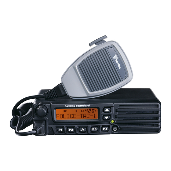
We’re glad you joined the VERTEX STANDARD team. Call on us anytime, be- cause communications is our business. Let us help you get your message across. - Page 5 NTRODUCTION The VX-4200 Series are full-featured FM transceiver designed for flexible mobile and base station business communications in the VHF or UHF Land Mobile bands. These transceiver are designed for reliable business communications in a wide vari- ety of applications with a wide range of operating capability provided by their lead- ing-edge design.
-
Page 6: Front Panel
Front Panel Important! - All buttons located on the Front Panel are Programmable Function (PF) Buttons, configured according to your network requirements and programmed by your VERTEX STANDARD dealer. The instructions below describe a typically- configured radio. VOL Knob Turn this control clockwise to increase the volume. - Page 7 & C ONTROLS ONNECTORS ( POWER ) Button Press and hold in this button for 2 seconds to toggle the transceiver’s power “on” and “off.” BUSY/TX Indicator Indicates transceiver’s Transmit/Receive Status Steady Red: Transmitting in progress Steady Green: Signaling Off Blinking Green: Busy Channel/Squelch Off [ ] / [ ] Buttons (Programmable Function Buttons) Pressing either button changes the current channel (and displayed channel num-...
-
Page 8: Rear Panel
& C ONTROLS ONNECTORS Rear Panel 13.6V DC Cable Pigtail with Connector The supplied DC power cable must be connected to this 2-pin connector. Use only the supplied fused cable, extended if necessary, for power connection. Antenna Socket The 50-Ohm coaxial feedline to the antenna must be connected here, using a type-M (PL-259) plug. -
Page 9: Setting The Volume
ASIC PERATION OF THE RANSCEIVER Important! - Before turning on the radio the first time, confirm that the power con- nections have been made correctly and that a proper antenna is connected to the antenna jack. Switching Power ON/OFF ( POWER ) button for 2 seconds to turn the radio on. Press and hold in the The display will become illuminated. -
Page 10: Key Lock
ASIC PERATION OF THE RANSCEIVER Automatic Time-Out Timer If the selected channel has been programmed for automatic time-out, you must limit the length of each transmission. While transmitting, a beep will sound 10 seconds before time-out. Another beep will sound just before the deadline; the red “TX” indicator will disappear and transmission will cease soon thereafter. -
Page 11: Table Of Contents
DVANCED PERATION Programmable Function (PF) Buttons The VX-4200 Series includes seven Programmable Function (PF) Buttons. The PF button functions can be customized, via programming by your VERTEX STAN- DARD dealer, to meet your communications/network requirements. Some features may require the purchase and installation of optional internal accessories. The pos- sible PF button programming features are illustrated below, and these functions are explained on the pages to follow. -
Page 12: Channel Down
DVANCED PERATION Description of Operating Functions ( MONI ) ONITOR Press the assigned programmable key to cancel CTCSS- and DCS-controlled squelch; the BUSY/TX indicator will glow green. Press and hold in this button for 1.5 sec- onds to hear background noise (unmute the audio); the BUSY/TX indicator will blink green. -
Page 13: Dw (Dual Watch)
DVANCED PERATION nel from the Scanning. When you delete a Group or channel, “ - - - - - SCAN Skip SCAN Skip - - - - - ” will SCAN Skip SCAN Skip SCAN Skip appear on the LCD for one second after pressing the assigned programmable key. To restore a particular channel to your scanning list, press and hold in the assigned programmable key again for one second;... -
Page 14: Follow-Me Scan
DVANCED PERATION OLLOW “Follow-Me” Scan feature checks a User-assigned Priority Channel regularly as you scan the other channels. Thus, if only Channels 1, 3, and 5 (of the 8 available channels) are designated for “Scanning,” the user may nonetheless assign Channel 2 as the “User-assigned”... -
Page 15: Encryption Disable
MERGENCY The VX-4200 series include an “Emergency” feature which may be useful if you have someone monitoring on the same frequency as your transceiver’s channel. Press the assigned programmable key to initiate an emergency call. For further de- tails contact your VERTEX STANDARD dealer. -
Page 16: Code Set
DVANCED PERATION Press the assigned programmable key to select a 5-Tone encode code from pre- defined encode list. Press the assigned programmable key to change the 5-Tone encodeing digit. To change the tones, select the desired digit using the [ P1 ] / [ P2 ] keys, then change the number using the [ ] / [ ] keys. -
Page 17: Horn Alert
DVANCED PERATION LERT Press the assigned programmable key to turn the Horn Alert function “ON” or “OFF.” If you receive a call from the base station with 2-Tone, 5-Tone or DTMF signaling, horn alert will be activated and your vehicles horn will sound. When you turn the Horn Alert “ON,”... - Page 18 DVANCED PERATION AF M Press the assigned programmable key to reduce the audio output to the (lower) level programmed by your Dealer. Press the assigned programmable key to activate the “User Set” (Menu) Mode. VX-4200 S ERIES PERATING ANUAL...
-
Page 19: Dtmf Paging System
DVANCED PERATION ARTS (Auto Range Transpond System) This system is designed to inform you when you and another ARTS-equipped sta- tion are within communication range. During ARTS operation, when the radio receives an incoming ARTS signal, a short beep will sound, and “In” (“In Service”) will be displayed on the sub-LCD. If you move out of range for more than two minutes, your radio senses that no signal has been received;... -
Page 20: Set
The VX-4200 Series includes a “User Set” (Menu) Mode which allows the user to define or configure various settings, such as Squelch, Display contrast, etc. To acti- vate the “User Set” (Menu) Mode: Press the programmable key assigned to the “SET” function. -
Page 21: Ptional A Ccessories
Desktop Microphone VPL-1 Programming Kit Availability of accessories may vary; some accessories are supplied standard per local requirements, others may be unavailable in some regions. Check with your VERTEX STANDARD Dealer for changes to this list. VX-4200 S ERIES PERATING ANUAL... - Page 22 VX-4200 S ERIES PERATING ANUAL...
- Page 23 SPAÑOL VX-4200 M ERIE ANUAL DE PERACIÓN...
- Page 24 Usted acaba de adquirir un valioso aparato de comunicación: ¡un transceptor VERTEX STAN- DARD! Resistente, seguro y fácil de usar, su nuevo radio VERTEX STANDARD le permitirá mantenerse en contacto permanente con sus colegas por muchos años más, y con el mínimo de interrupciones para realizar su manutención a través del tiempo.
- Page 25 EEPROM en la Unidad de Procesamiento Central que el distribuidor programa con toda facilidad utilizando una computadora personal, el Cable de Programación VPL-1 de VERTEX STANDARD y la rutina para ordenadores CE59. En las páginas siguientes se ofrece una descripción detallada de las diversas y avanzadas funciones que poseen los transceptores de la Serie VX-4200.
-
Page 26: Panel Frontal
Alto o Bajo de potencia, la función de Monitoreo, la Comunicación Directa, etc., de acuerdo con los requisitos de la red a la que pertenece y a la programación que realice el distribuidor VERTEX STANDARD de su localidad. Botón [ A ] ( Botón de Funciones Programable ) Este botón se puede configurar para ejecutar ciertas aplicaciones especiales, tales como... - Page 27 & C ONTROLS ONNECTORS Botón de Encendido ( POWER ) Oprima este botón durante 2 segundos para “encender” y “apagar” el transceptor. Indicador de Ocupación y Transmisión “BUSY/TX” Da a conocer el Estado de Transmisión o Recepción del transceptor Rojo Uniforme: Transmisión en curso Verde Uniforme: Señal de desconexión...
- Page 28 & C ONTROLS ONNECTORS Panel Posterior 1. Cable Flexible para 13.6 V de CC con Conector El cable de alimentación de CC que se suministra con el aparato se debe acoplar a este conector de 2 alfileres de contacto. Utilice solamente el cordón con fusible que incluye el fabricante, extendiéndolo si fuera necesario, para hacer las conexiones a la fuente de alimentación.
- Page 29 UNCIONAMIENTO ÁSICO DEL RANSCEPTOR ¡Importante! – Antes de encender el radio por primera vez, verifique que se hayan realizado adecuadamente las conexiones a la fuente de alimentación y que también se haya conectado la antena apropiada en el enchufe. Conexión y Desconexión del Transceptor Oprima el interruptor de conexión ( POWER ) durante 2 segundos para encender el radio.
- Page 30 UNCIONAMIENTO ÁSICO DEL RANSCEPTOR De haber programado la Función de Bloqueo mediante el Sistema de Silenciamiento CTCSS o Código Digital DCS en un determinado canal, el radio podrá transmitir mientras no se reciba ninguna portadora o cuando la portadora que se reciba contenga el tono CTCSS o código DCS correcto. Temporizador Automático de Intervalos de Transmisión El usuario debe limitar la duración de cada transmisión si el canal seleccionado ha sido programado para que se desconecte en forma automática al cumplirse el intervalo de retardo.
-
Page 31: Requires Optional Unit
El usuario puede configurar a su gusto las funciones de estos controles mediante la programación que realiza el distribuidor VERTEX STANDARD de su localidad, de tal forma de satisfacer sus propios requisitos de explotación así como los de la red a la que pertenece. Es posible que algunas funciones prescriban la compra e instalación de accesorios optativos... - Page 32 UNCIONAMIENTO VANZADO Descripción de las Funciones del Transceptor Monitoreo ( MONI ) Oprima el botón programable asignado para cancelar el sistema de silenciamiento controlado por Tono o Código Digital; en tal caso, el indicador BUSY/TX se enciende de color verde. Oprima firmemente el referido botón durante 1,5 segundos cuando desee escuchar el ruido de fondo (o desenmudecer el audio);...
- Page 33 UNCIONAMIENTO VANZADO Exploración de Canales ( SCAN ) La función de Exploración se utiliza para vigilar múltiples canales programados en el transceptor. Durante el referido proceso, el radio analiza cada uno de esos canales en busca de actividad, y se detiene cuando detecta la presencia de una señal en cualquiera de ellos. Para activar el circuito de barrido: Oprima el botón programable asignado a fin de hacer efectiva la actual función.
- Page 34 UNCIONAMIENTO VANZADO Exploración con Seguimiento Automático de Canales ( F OLLOW La función de Exploración con “Seguimiento Automático” de Canales vigila regularmente un Canal Prioritario designado por el Usuario al mismo tiempo que explora el resto de los canales seleccionados. De esta forma, si sólo se destinan los canales 1, 3 y 5 (de los 8 disponibles) para la “exploración”, entonces el usuario podrá...
- Page 35 Oprima el botón programable asignado con el objeto de iniciar una llamada de emergencia. Para mayores detalles sobre el tema, contáctese con el representante VERTEX STANDARD de su localidad.
- Page 36 UNCIONAMIENTO VANZADO LLAMADA/REPOSICIÓN ( C ESET Esta función, de haber sido habilitada, le permite al usuario cambiar el código de tres dígitos para Aviso de Llamada, el cual se utiliza para comunicarse con otras estaciones equipadas con sistemas de este tipo. Oprima la tecla programable asignada, seguida de los tres dígitos que representan el código para Aviso de Llamada de la estación con la cual desea establecer contacto.
- Page 37 UNCIONAMIENTO VANZADO Discado Automático de Números ( S PEED Es posible que el distribuidor haya programado memorias con números telefónicos para Discado Automático en su radio. Para marcar un número, oprima la tecla programable asignada para esta función y a continuación, accione la tecla numérica correspondiente a la lista para discado automático que prepara el Distribuidor.
- Page 38 UNCIONAMIENTO VANZADO Acceso Directo Canal #1 al #4 ( D CH#4 ) CH#1 IRECT IRECT Oprima el botón programable asignado a fin de recuperar un canal configurado por el Distribuidor en forma directa. GRABAR/TOCAR ( REC/PLAY “Unidad de Registro de la Voz: Optativa” ) Esta función, la cual estipula el uso de la Unidad optativa de Registro de la Voz, le permite grabar y reproducir el audio del receptor de entrada.
- Page 39 UNCIONAMIENTO VANZADO Recepción por la Subbanda (Optativa) Esta función se puede utilizar solamente en aquellos radios en donde la Unidad de Recepción optativa para la Subbanda ha sido instalada. Cuando se instala este módulo alternativo en el aparato, usted podrá recibir por una banda distinta a la que normalmente utiliza el transceptor (por ejemplo, en un radio VHF, este módulo hace posible la recepción por UHF y viceversa).
- Page 40 ODO DE ROGRAMACIÓN DEL SUARIO La Serie VX-4200 incluye un Modo de Programación (del Menú) que le permite al Usuario determinar o configurar una amplia variedad de parámetros conforme a sus propias especificaciones, tales como el Nivel de Silenciamiento, el contraste de la Pantalla, por nombrar algunos.
- Page 41 NDICADOR ESCRIPCIÓN 1 1 1 1 1 SQL Define el Nivel de Silenciamiento 2 2 2 2 2 SCN List SCN List SCN List SCN List SCN List Selecciona la Lista de Exploración preparada por el “Usuario” o el “Distribuidor” 3 3 3 3 3 BEEP BEEP BEEP...
- Page 42 Comuníquese con el representante VERTEX STANDARD de su localidad para ver las modificaciones realizadas a esta lista.
- Page 43 Part 15.21: Changes or modifications to this device not expressly ap- proved by Vertex Standard could void the user’s authorization to oper- ate this device.
- Page 44 Copyright 2012 Printed in Japan Vertex Standard LMR, Inc. All rights reserved. No portion of this manual may be reproduced without the permission of Vertex Standard LMR, Inc.