Table of Contents
Advertisement
Advertisement
Table of Contents

Related Manuals for Custom Audio Electronics s’print DPT100-B


Summary of Contents for Custom Audio Electronics s’print DPT100-B
- Page 1 User Manual Portable thermal printer s’print www.custom.it DPT100-B/I/BT...
- Page 2 All rights reserved. Total or partial reproduction of this manual in whatever form, whether by printed or electronic means, is forbidden. While guaranteeing that the information contained in it has been carefully checked, CUSTOM ENGINEERING SPA and other entities utilized in the realization of this manual bear no responsibility for how the manual is used.
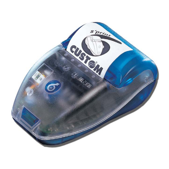
- Page 3 PRINTER COMPONENTS A. DPT100-B – Front external view 1- Printer base 2- Cover 3- Paper holder 4- Printing mechanism 5- Multi-function + ON key 6- Paper exit slot 7- Infrared device B. DPT100-B – Under view 1- Serial connector and battery recharger 2- Battery compartment DPT100-B/I/BT...
- Page 4 Blank page DPT100-B/I/BT...
-
Page 5: Table Of Contents
TABLE OF CONTENTS INTRODUCTION MANUAL CONTENTS ............................1 EXPLANATORY NOTES USED IN THIS MANUAL ................... 1 GENERAL SAFETY INFORMATION ........................ 1 UNPACKING THE PRINTER ........................... 2 PRINTER FEATURES ............................. 3 PRINTER DESCRIPTION ..........................4 1. INSTALLATION AND USE 1.1 CONNECTIONS ............................. 1-1 1.1.1 Battery recharger .......................... - Page 6 TABLE OF CONTENTS 3. PRINTER FUNCTIONS 3.1 CONTROL CHARACTERS ........................3-1 3.1.1 Emulation ............................3-1 4. TECHNICAL SPECIFICATIONS 4.1 TECHNICAL SPECIFICATIONS ......................4-1 4.2 ADAPTOR SPECIFICATIONS ........................ 4-4 4.3 DIMENSIONS ............................4-5 5. CHARACTER FONTS 5.1 CHARACTER SETS ..........................5-1 APPENDIX A - ACCESSORIES AND SPARE PARTS A.1 TICKET ALIGNMENT ..........................
-
Page 7: Introduction
INTRODUCTION MANUAL ORGANIZATION In addition to the Introduction which includes a description of the explanatory notes used in the manual, general safety information, how to unpack the printer and a brief description of the printer including its basic features, this manual is organized as follows: Chapter 1: Contains the information required for correct printer installation and its proper use, as well as interface specifications... -
Page 8: Unpacking The Printer
INTRODUCTION UNPACKING THE PRINTER Remove the printer from its carton being careful not to damage the packing material so that it may be re-used if the printer is to be transported in the future. Make sure that all the components illustrated in fig. 1 are present and that there are no signs of damage. If there are, contact Customer Service. -
Page 9: Printer Description
INTRODUCTION It has a 203 dpi thermal print mechanism that utilizes 57.5mm-wide paper rolls and can print up to 24 o 40 charaters per line. NOTE: The 40 column version is downloadable on the Support/Download/Firmware section from www.custom.it web site. PRINTER DESCRIPTION The printers consists of a ABS-V0 casing (1) equipped with a cover (2) under which is housed the paper roll and print mechanism. - Page 10 INTRODUCTION Blank page DPT100-B/I/BT...
-
Page 11: Installation And Use
1. INSTALLATION AND USE 1.1 CONNECTIONS (Fig.1.1) 1.1.1 Battery Recharger For the Battery Recharger/Power Supply and serial connection, the printer is equipped with a connecting cable (fig. 1.2) that comes packed with the printer and has a double connection system. On one side is a 9- pin female connector (fig. -
Page 12: Batteries
1. INSTALLATION AND USE Turning the printer On and Off using software commands If the printer is off, sending a characters set on the serial line will turn it on . Follow the instructions shown (2)(3) in the diagram below: START NOTE (Fig.1.3) -
Page 13: Information Regarding Battery Use
1. INSTALLATION AND USE NOTE: During the recharge operation it’s not possible turning the printer off. WARNING Incorrect battery recharge voltage (different from that given in tab.1.2) could seriously damage the printer. Tables 1.1 and 1.2 provide specifications for the battery recharger (Tab.1.1) (Tab.1.2) 1.2.2 Information regarding battery use... -
Page 14: Disposing Of Batteries
1. INSTALLATION AND USE (Fig.1.5) • remove the battery pack (2) by lifting the battery removal tape (1) (see fig. 1.6). (Fig.1.6) • insert the 5 batteries inside the compartment following the layout indicated in fig. 1.7 and re-position the battery removal tape; Note: when inserting the batteries, make sure the + and –... -
Page 15: Configuration
1. INSTALLATION AND USE 1.3 CONFIGURATION 1.3.1 Configuration Mod. DPT100-B/I The printer set up print out (see fig. 1.9) includes a range of information, and among these should be pointed out the HEAD VOLT parameter that indicates the battery charge level, i.e., the print head battery voltage. * SETUP DEFAULT * HEAD TEMP. -
Page 16: Configuration Mod. Dpt100-Bt
1. INSTALLATION AND USE Note: 0If the Interface parameter is set in infrared and flow control is required, any time a transmission is effected a time break of one time and a half the byte transmission is needed (for example 1.5 msec at 9600 bps). The reason is for Half Duplex type of infrared line communication. As a result the Busy condition check must be waited when transmitting data to the printer. - Page 17 1. INSTALLATION AND USE The printer’s configurable parameters, with Bluetooth wireless technology interface selected, are: • Interface: BT , RS232. • BT Name ID : NO ID , #0, #1, #2, #3, #4, #5, #6, #7, #8, #9. (14) • Authentication (15) : Enabled, Disabled...
-
Page 18: Hexadecimal Dump
1. INSTALLATION AND USE 1.4 HEXADECIMAL DUMP This function is used to display the characters received from the communications port; after the reception of each 6 characters from the communications port, the printer prints out both the hexadecimal code received as well as the corresponding ASCII code. - Page 19 1. INSTALLATION AND USE (Fig.1.13) Pull up on the edge of the paper and close the cover (fig. 1.14); (Fig.1.14) Tear off the paper. The printer is now ready (fig.1.15). (Fig.1.15) DPT100-B/I/BT...
-
Page 20: Cleaning
1. INSTALLATION AND USE 1.6.2 Cleaning To clean the printer, use a vacuum cleaner or soft cloth. Before cleaning the printer, unplug its electrical cord and make sure that the printer is off. Do not use alcohol, solvents or hard-bristled brushes. Do not let water or other liquids seep into the printer. -
Page 21: Interfaces
2. INTERFACES (Fig.2.1) 2.1 RS232 SERIAL The printer is equipped with an RS232 serial interface with RJ11 connector (fig. 2.1) located underneath the printer. For serial connection, a connecting cable (fig. 2.2) with double connection system is packed with the printer. - Page 22 2. INTERFACES 9-pin female connector (fig. 2.2.A) (Tab.2.2) i r r c i f v i t l a i l a i v i t v i t The diagrams below show a sample connection between printer and Personal Computer using a 9- and 25- pin female connector.
-
Page 23: Infrared Bidirectional Serial
2. INTERFACES SIGNAL GND (Fig.2.5) 9-pin connector (s’print cable) 2.2 INFRARED BIDIRECTIONAL SERIAL (only DPT100-B model) The printer has a serial interface for bidirectional data exchange. The infrared port is centered on the power part of the front (see fig. 2.4); it uses the encode method bits as described in the IrDA physical layer, for speeds up to 115.2 kbps (a 3/16th optical pulse time of bit time). -
Page 24: Standard Mode
2. INTERFACES To utilize the infrared bidirectional serial interface, it must first be enabled under setup (parameter: “Interface: Infrared”). It is possible to communicate with the printer in two different ways: by sending a string of characters and/or commands preceded by the IR port Open command and followed by a Close command (standard mode), or by utilizing a simple transfer protocol that guarantees that data is compressed correctly by the printer. -
Page 25: Infrared Communication Protocol
2. INTERFACES 2.2.2 InfraRed communication protocol To utilize the IR communication protocol, the “IR Protocol” must first be set to “Enabled” under setup. The transfer protocol is structured as follows: [1byte] = $02 Start Transmission ID LUNG [1byte] = number of bytes in the transmitted data field. The maximum number of bytes to be transmitted must be <=48. -
Page 26: Printing Instructions
2. INTERFACES An ACK response is returned in the event the entire protocol was interpreted correctly and the check sum calculated is the same as that received by the host. A NACK response is returned in the event of transmission errors that cause a discrepancy between the calculated and received check sums. -
Page 27: Irda Protocol Overview
2. INTERFACES 2.3 IrDA PROTOCOL OVERVIEW (only DPT100-I model) This paragraph contains a general overview information about IrDA protocol implemented on the printer. For further detrils about the complete IrDA standard specifications are available from the IrDA website www.IrDA.org. The IrDA standard specifies the following protocols: •... -
Page 28: Irda Data Protocols Supported
2. INTERFACES 2.3.1 IrDA DATA PROTOCOLS SUPPORTED The printer supports these required IrDA standard protocols: • Physical Signaling Layer(PHY) • Link Access Protocol(IrLAP) • Link Management Protocol/information Access Service(IrLMP/IAS) The printer also supports some of the optional protocols for IrDA data. The optional protocols that the printer implements are: •... -
Page 29: Irlmp
2. INTERFACES performance of the link are part of this function. These parameters control how many BOFs are used, identify the speed of the link, how fast either party may change from receiving to transmitting, etc. IrLAP has the responsbility of negotiating these parameters to the highest common set so that both sides can communicate as fast and as reliably as possible. -
Page 30: 3-Wire Raw And Irlpt In Detail
2. INTERFACES (Fig.2..10) IrCOMM Service Uncooked Cooked Services Services Parallel Serial Serial Parallel Centronics 3-wire Cooked 3-wire Raw IrLPT 9-wire Cooked IEEE 1284 Supported by printer 2.3.1.5.1 3-Wire Raw and IrLPT in Detail 3-Wire raw and IrLPT may be used to emulate either serial or parallel ports in cases where a single exclusiveconnection is satisfactory. -
Page 31: Basic Link Operation
2. INTERFACES 2.3.1.5.4 Basic link operation 3-Wire raw connections must be exclusive - that is, all other non-IAS connections must terminate before the raw connection is made, and all others must wait until the raw connection is broken before they can connect. This is because 3-Wire raw uses IrLAP flow control, which flow controls off the entire physical link - multiple connections under this scenario could result in deadlock. -
Page 32: Serial Port Profile
2. INTERFACES 2.4.1.1 Serial Port Profile The Serial Port Profile provides RS232 serial cable emulation for Bluetooth wireless technology devices. In this way, legacy applications do not have to be modified to use Bluetooth technology; they can simply treat Bluetooth wireless link as a serial cable link. The Serial Port Profile uses RFCOMM to provide serial port emulation. -
Page 33: Printer Functions
3. PRINTER FUNCTIONS 3.1 CONTROL CHARACTERS The command table lists all the commands for the management of the printer functions. These commands can be transmitted to the printer with the serial interface. The commands can be transmitted to the printer at any moment, but they will only be carried out when the characters previously transmitted have been printed or the commands previously transmitted have been carried out. - Page 34 3. PRINTER FUNCTIONS [Name] Small character printing [Format] ASCII Decimal [Description] The printer prints in small characters (normal) [Notes] • The commands $00 - $09 do not cancel the print buffer • The commands which modify the direction of the characters are only active at the beginning of the line [Default] Setting in option register by means of front keys...
- Page 35 3. PRINTER FUNCTIONS • the commands which modify the dimensions of the characters are only active at the beginning of the line [Default] Setting in the option register by means of the front keys [Reference] $00, $01, $02, $04 [Example] [Name] Restore small character printing [Format]...
- Page 36 3. PRINTER FUNCTIONS [Description] Carries out the number of line feeds specified in (n) [Notes] •The number must be ASCII and between 0 and 9 (when n=0 the command is ignored) • This command clears the line buffer [Default] [Reference] [Example] To forward feed fast, 5 lines at a time: $35 $0B (or 5 and the command $0B)
- Page 37 3. PRINTER FUNCTIONS where: X is not used (0 is recommended); R must be fixed at level 1; P1,...,P6 are the graphic dot data (1 prints, 0 does not print). The P6 bit of the string of dots transmitted is printed on the right and the others follow from right to left (P5, P4, P3, P2, P1) as shown: 2 byte N byte...
- Page 38 3. PRINTER FUNCTIONS [Name] Transmit printer ID [Format] ASCII Decimal 1 ≤ n ≤ 3, 49 ≤ n ≤ 51 [Range] [Description] Transmits the printer ID specified by n follows: [Notes] • This command is executed when the data is processed in the data buffer. Therefore, there could be a time lag between command reception and data transmission, depending on data buffer status.
- Page 39 3. PRINTER FUNCTIONS [Example] This can be useful during switching on in order to avoid the sending of false characters during initialization by the master device. [Name] Executes [n] dots line feed [Format] ASCII Decimal [Description] Executes [n] dots line feed. [Notes] [Default] [Reference]...
- Page 40 3. PRINTER FUNCTIONS $00 small character printing $01 double width printing $02 double height printing $03 expanded printing [Notes] • The setting is stored in the EEPROM [Default] Setting by means of the front keys [Reference] $1B $6D [Example] For small character printing, transmit: $30 $30 $1B $4D For double height printing, transmit: $30 $32 $1B $4D...
- Page 41 3. PRINTER FUNCTIONS [Name] Prints a graphic line at 200 dpi [Format] ASCII Decimal [Description] After receiving this command, the printer waits for 48 bytes which correspond to an entire graphic line. In fact, 48 bytes of 8 bits each correspond to 384 dots per line. [Notes] [Default] [Reference]...
- Page 42 3. PRINTER FUNCTIONS t i s [maximum length] Interleaved 2/5 = 12 characters Code 39 = 10 characters CodaBar = 10 characters EAN8 = 8 characters EAN13 = 13 characters [data] = Expressed in ASCII. [Notes] [Default] [Reference] [Example] [Name] Transmits the print mode in serial [Format] ASCII...
- Page 43 3. PRINTER FUNCTIONS [Notes] • If the printer is using the parallel protocol, nothing with be transmitted [Default] Setting in the option register by means of the front keys [Reference] $1B $4D [Example] The response is on two bytes. E.g. if you receive: $30, $32 it means that printing is in double height mode [Name] Disables underlined printing...
- Page 44 3. PRINTER FUNCTIONS [Name] Transmit paper sensor status [Format] ASCII Decimal [Description] When this command is received, transmit the current status of the paper sensor. [Notes] • This command is executed immediately, even when the data buffer is full (Busy ). The status to be transmitted is shown in the table below: 0 1 , y l r...
- Page 45 3. PRINTER FUNCTIONS 1 ≤ n ≤ 3, 49 ≤ n ≤ 51 [Range] [Description] Transmits the printer ID specified by n follows: t n i [Notes] • This command is executed when the data is processed in the data buffer. Therefore, there could be a time lag between command reception and data transmission, depending on data buffer status.
- Page 46 3. PRINTER FUNCTIONS [Example] For printing 12 bytes the command sequence is : $1D $57 $0C $FF $00 $FF $00 $FF $00 $FF $00 $FF $00 $FF $00 [Name] Aligns the ticket at the first printed line [Format] ASCII (nH) (nL) (nH) (nL)
-
Page 47: Technical Specifications
4. TECHNICAL SPECIFICATIONS 4.1 TECHNICAL SPECIFICATIONS Table 4.1 gives the main technical specifications for the model DPT 100-B/I. (Tab.4.1) ± ° 0 n i l i d i g i l ° ÷ ° v i t y t i y t i °... - Page 48 4. TECHNICAL SPECIFICATIONS Table 4.2 gives the main technical specifications for the Bluetooth wireless technology model DPT 100-BT (Tab.4.2) ± n i l g i l ° ÷ ° v i t y t i y t i ° ÷ °...
- Page 49 4. TECHNICAL SPECIFICATIONS (Tab.4.3) a l i t f i l a i l i f e l i l i f NOTE: The 40 column version is downloadable on the Support/Download/Firmware section from www.custom.it web site. DPT100-B/I/BT...
-
Page 50: Adaptor Specifications
4. TECHNICAL SPECIFICATIONS LED safety The infrared port on the front of the printer conforms to Class 1 for LED devices (light-emitting diode), on the basis of international standard IEC 825-1 (EN 60825-1). This device is not considered harmful, but the following precautions should be observed: •... -
Page 51: Dimensions
4. TECHNICAL SPECIFICATIONS 4.3 DIMENSIONS Printer dimensions are shown below. (Fig.4.1) 213,9 88,18 64,61 DPT100-B/I/BT... - Page 52 4. TECHNICAL SPECIFICATIONS Blank page DPT100-B/I/BT...
-
Page 53: Character Sets
5. CHARACTER SETS 5.1 CHARACTER SETS The printer has a 224-character font, a print-out of which is shown below. (Fig.5.1) DPT100-B/I/BT... - Page 54 5. CHARACTER SETS Blank page DPT100-B/I/BT...
-
Page 55: Appendix A - Accessories And Spare Parts
APPENDIX A - ACCESSORIES AND SPARE PARTS A.1 TICKET ALIGNMENT A.1.1 Ticket alignment Paper stock with alignment marks is permitted so that tickets of a fixed length or with pre-printed areas may be utilized.To guarantee proper alignment, the “Alignment” parameter must be enabled under setup using the key (see: setting configuration parameters) The notch mark must be placed on the termic side of the ticket itself (printable area) . -
Page 56: Accessories
APPENDIX A - ACCESSORIES AND SPARE PARTS A.2 ACCESSORIES A.2.1 Belt coupler In the s’print-B battery model, there is a support kit available for the printer that consists of a belt and fastening screws. The figure below illustrates how the belt coupler is attached underneath the printer. (Fig.A.1) A.3 SPARE PARTS (Tab.A.2)