Table of Contents
Advertisement
Advertisement
Table of Contents

Related Manuals for Custom Audio Electronics VKP80II


Summary of Contents for Custom Audio Electronics VKP80II
- Page 1 USER MANUAL VKP80II VKP80II 77200000001600 Commands manual...
- Page 3 CUSTOM ENGINEERING S.p.A. GENERAL SAFETY INFORMATION THE CE MARK AFFIXED TO Your attention is drawn to the following THE PRODUCT CERTIFY Str. Berettine 2 actions that could compromise the char- THAT THE PRODUCT SAT- 43010 Fontevivo (PARMA) - Italy acteristics of the product: ISFIES THE BASIC SAFETY Tel.
-
Page 5: Table Of Contents
Power supply dimensions cod.963GE020000003 (optional) ..............49 Paper specifi cations ........................... 50 Western characters ............................ 52 8 CONSUMABLES ..............................59 9 ACCESSORIES ..............................61 Adapter cable for power supply ........................62 Paper roll holder ............................63 “Shutter” device ............................65 VKP80II 5 User Manual... - Page 6 INDEX 10 ALIGNMENT ................................ 67 10.1 Enable alignment ............................67 10.2 Calibration ..............................67 10.3 Alignment parameters ..........................69 10.4 Printing area ............................... 71 11 TECHNICAL SERVICE ............................73 6 VKP80II User Manual...
-
Page 7: Introduction
1.2 Explanatory notes used in this manual NOTE: Information or suggestions relative to the use of the printer. ATTENTION: Information required to guard against damaging the printer. DANGER: Information required to guard against operator injury or damage. VKP80II 7 User Manual... - Page 8 1. INTRODUCTION 8 VKP80II User Manual...
-
Page 9: Description
Take out the foam packing shell • Take out the printer and remove it from its plastic covering. • Keep the box, trays and packing materials in the event the printer must be transported/shipped in the future.. VKP80II 9 User Manual... -
Page 10: Printer Component
2. DESCRIPTION 2.2 Printer component EXTERNAL FRONTAL VIEW 1. Opening lever 2. RS232 serial connector 3. USB connector 4. Power supply connector 5. Paper output 6. Cutter 10 VKP80II User Manual... - Page 11 2. DESCRIPTION EXTERNAL REAR VIEW 1. Left cursor for paper input 2. Paper input 3. Right cursor for paper input 4. FORM FEED key 5. LINE FEED key 6. Status led VKP80II 11 User Manual...
-
Page 12: Key Functions
2.3 Key functions The following fi gures show the functions of printer’s keys according to the operating condition of the device. STANDBY Fast push Fast push Advance the paper Advance the paper (manual insertion) (preset length) 12 VKP80II User Manual... - Page 13 2. DESCRIPTION POWER UP Hold down Hold down print the print the SETUP report FONT TEST Fast push Fast push skip the enter the SETUP MODE SETUP MODE Fast push Fast push next modify parameter selected parameter VKP80II 13 User Manual...
-
Page 14: Status Led Fl Ashes
RECEPTION ERRORS (PARITY, FRAME ERROR, OVERRUN ERROR) GREEN COMMUNICATION STATUS COMMAND NOT RECOGNIZED COMMAND RECEPTION TIME OUT HEADING OVER TEMPERATURE PAPER END YELLOW PAPER JAM RECOVERABLE ERROR POWER SUPPLY VOLTAGE INCORRECT COVER OPEN RAM ERROR EEPROM ERROR UNRECOVERABLE ERROR CUTTER ERROR 14 VKP80II User Manual... -
Page 15: Installation
Lv ≤ Pn + Sp where Lv : indicates screw length Pn : 8 mm Sp : panel thickness For example if panel thickness is 10mm ( Sp = 10mm ) the max screw length will be 18mm. VKP80II 15 User Manual... - Page 16 The reference (1) indicates the screws that must located in the two external holes in front of the printer; the refer- ence (2) indicates the screw that must located in the center hole of the rear side of the printer. 16 VKP80II User Manual...
-
Page 17: Installation And Use With "Retracting" Mode
When assembling the printer on the machine, be sure to leave adequate space for the paper loop below. If this is not done, the ticket could crease at the cutting area, causing the ticket to jam in the paper outfeed opening. VKP80II 17 User Manual... -
Page 18: Connections
3. INSTALLATION 3.3 Connections The following fi gures show the possible connections for device. POWER SUPPLY RS232 ATTENTION: In some using conditions, we recommend the installation of a ferrite core on the power supply cable. 18 VKP80II User Manual... -
Page 19: Pinout
Female Molex connector series 5557 (n.39-01-3022) Cable Signal color +24V Black Power supply cable USB INTERFACE Female USB type B connector 1 USB-VBUS (in) 2 D - (in/out) 3 D + (in/out) 4 GND SH1 SHIELD SH2 SHIELD VKP80II 19 User Manual... -
Page 20: Rs232 Serial Interface
+15 Vdc and logic value “1” corresponds to a voltage level of between -3 Vdc and -15 Vdc. Note: VKP80II > PC connection The following pictures show an example of connections between the printer and a personal computer using a 9... -
Page 21: Driver
Follow the instruction get back on the README.TXT fi le you can fi nd it in the Linux software package downloaded in advance. All drivers can be found in the DOWNLOAD section of the web site www.custom.biz. VKP80II 21 User Manual... - Page 22 3. INSTALLATION 22 VKP80II User Manual...
-
Page 23: Operation
Move the right and left slides to adjust the paper width (see following fi gure). Below the right slide there are four point of reference for paper width (60, 70, 80 and 82.5mm). Move the slides to align the internal side of the fi n (A) with the point of reference. VKP80II 23 User Manual... -
Page 24: Paper Roll Insertion
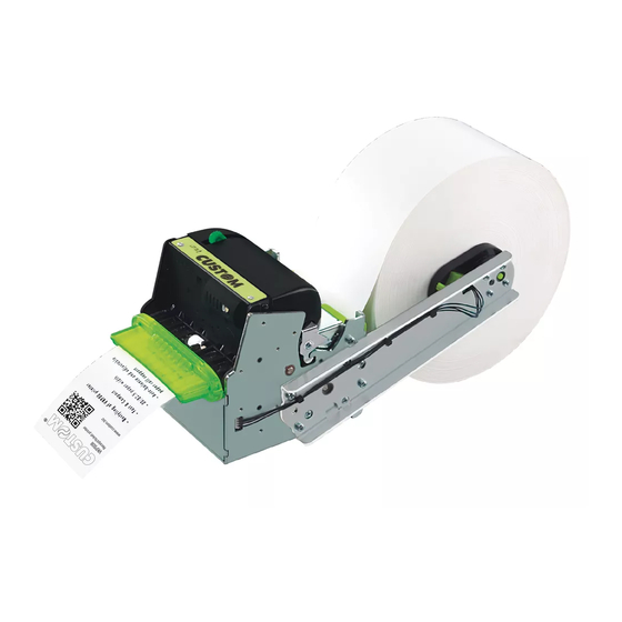
ATTENTION: Make sure the cut is straight. Position the paper roll, so that it unrolls correctly as shown in figure. ROOM Insert the paper into the paper infeed opening and wait for it to load automatically. 24 VKP80II User Manual... - Page 25 The following fi gure gives the limit positions of the paper roll related to the printer for a correct paper loading without a paper roll holder support. The direction of the paper will always form a maximum angle of 90 ° or -90 ° with the insertion plane of paper inside the printer. 90° 90° -90° -90° VKP80II 25 User Manual...
- Page 26 4. OPERATION 26 VKP80II User Manual...
-
Page 27: Configuration
(hold down) LINE FEED FORM FEED RS232 POWER SUPPLY During power-up, hold down the LINE FEED key while the wiring is plugged into the power supply connector of the printer. The device prints a SETUP report. VKP80II 27 User Manual... - Page 28 When the FORM FEED key is pressed, the printer enters parameter confi guration. When the LINE FEED key is pressed, the printer exits setup and terminates the Hexadecimal dump function. 28 VKP80II User Manual...
-
Page 29: Setup Report
Speed / Quality......: Normal Paper Retracting .......: Disabled Notch Alignment ......: Disabled Notch Threshold ......: 2.0V Notch Distance [mm] ....: Current ........: Normal Print Density......: [FF] key to enter setup KEYS FUNCTIONS [LF] key to skip setup VKP80II 29 User Manual... -
Page 30: Printer Status
RETRACT COUNTER is given the number of “retract” made CUT COUNTER is given the number of cuts made. POWER ON COUNTER is given the number of power-ups made 30 VKP80II User Manual... -
Page 31: Printer Parameters
NOTE: The Status Monitor is an additional printing driver component that allows the printer status moni- toring. It must be enabled only if the Status Monitor specifi c driver was installed. Setting of the Carriage Return character: AUTOFEED CR disabled = Carriage Return disabled CR enabled = Carriage Return enabled VKP80II 31 User Manual... - Page 32 NOTE: In Setup mode, it is possible to set the notch distance using a values range from 0mm to 39mm. The maximum distance accepted is 32mm, so even if values from 33mm to 39mm are inserted, the distance remains 32mm. 32 VKP80II User Manual...
- Page 33 5. CONFIGURATION Setting of the current consumption: CURRENT High Normal Adjusting the printing density: PRINT DENSITY -50% -12% +25% -37% +37% -25% +12% +50% VKP80II 33 User Manual...
-
Page 34: Hexadecimal Dump
6B 6C 73 64 66 68 6B 73 klsdfhks 64 66 6B 73 64 66 68 6A dfksdfhj 73 64 66 6B 6A F2 73 64 66 6B F2 6A 73 68 64 66 6A 6B 6C 68 jklh 34 VKP80II User Manual... -
Page 35: Maintenance
EVERY 6 MONTHS OR AS NEEDED Printer case Use compressed air or a soft cloth For specifi c procedures, see the following pages. NOTE: If you use the device in dusty environments, you must reduce the intervals between the cleaning operations. VKP80II 35 User Manual... -
Page 36: Cleaning
Do not perform any opera- by using compressed air. tion inside printer immediately after printing because head motor tend to become very hot. Rotate the printing group B to the locking position. 36 VKP80II User Manual... - Page 37 Carefully clean the notch and the paper presence Do not perform any opera- sensors by using compressed air. tion inside printer immediately after printing because head motor tend to become very hot. Rotate the printing group B to the locking position. VKP80II 37 User Manual...
- Page 38 Do not let water or other liquids get inside the machine. To remove paper scraps, use tweezers or compressed air. Alcohol, solvent cohol, solve Clean the paper input and output by using compressed air. Rotate the printing group B to the locking position. 38 VKP80II User Manual...
- Page 39 Do not perform any opera- tion inside printer immediately after printing because head Clean the printing head by using a motor tend to become very soft cloth moistened with isopropyl hot. Rotate the printing group B to the locking position. VKP80II 39 User Manual...
- Page 40 Do not perform any opera- tion inside printer immediately after printing because head motor tend to become very hot. Rotate the printing group B to the locking position. 40 VKP80II User Manual...
- Page 41 ATTENTION: Do not use alcohol, solvents, or hard brushes. Do not let water or other liquids get inside the machine. Alcohol, solvent cohol, solve To clean the machine, use pneumatic air or soft cloth. VKP80II 41 User Manual...
-
Page 42: Upgrade Fi Rmware
(see paragraph 3.3). 6. Switch ON the printer. 7. Start the software UPGCEPRN. 8. Select the update fi le .PSW location : 12. Print a new SETUP report to verify the new fi rmware release (see chapter 5). 42 VKP80II User Manual... - Page 43 6. MAINTENANCE UPDATE VIA USB INTERFACE 9. Select item USB and then select the USB device among those proposed (ex. VKP80II): ATTENTION: Only during the fi rmware update, the connection between PC and printer must be direct, without the use of wireless HUB.
- Page 44 6. MAINTENANCE 44 VKP80II User Manual...
-
Page 45: Specifications
60 mm to 82,5 mm max 180 mm External roll diameter upper fi xing : max 150 mm rear or lower fi xing : max 180 mm Internal roll core diameter 25 mm Core type Cardboard or plastic VKP80II 45 User Manual... - Page 46 7. SPECIFICATIONS ELECTRICAL SPECIFICATIONS VKP80II Power supply 24 Vdc ±10% (optional external power supply) Medium consumption (6) (7) Stand-by consumption 0,04 A ELECTRICAL SPECIFICATIONS POWER SUPPLY cod.963GE020000003 (OPTIONAL) Power supply voltage from 100Vac to 240Vac Frequence from 50Hz to 60Hz Current (output) 24 Vdc ±...
-
Page 47: Character Specifi Cations
Ticket length Ticket presentation 60 mm 10 mm “Ejecting” function > 80 mm 10 mm - 30 mm 350 mm 10 mm - 30 mm NOTE: : Maximum length recommended to guarantee the printer effi ciency. VKP80II 47 User Manual... -
Page 48: Printer Dimensions
7. SPECIFICATIONS 7.4 Printer dimensions Length 149,5 mm Height 121,2 mm Width 123,5 mm Weight 1600 g +0,5 85,5 -0,5 -0,5 123,5 125,5 149,5 NOTE: Referred to printer models without paper roll holder optional. 48 VKP80II User Manual... -
Page 49: Power Supply Dimensions Cod.963Ge020000003 (Optional)
7. SPECIFICATIONS 7.5 Power supply dimensions cod.963GE020000003 (optional) Length 127 mm Height 35,5 mm Width 56 mm AC INLET +24V DC OUTPUT WIRE VKP80II 49 User Manual... -
Page 50: Paper Specifi Cations
The notch must be positioned on the non-thermal side of the paper as shown in the following fi gures, showing some example of paper with alignment notch depending on the paper width. NOTCH ON 60mm PAPER Sensor axis Paper axis NON-THERMAL SIDE NOTCH ON 75mm PAPER Sensor axis Paper axis NON-THERMAL SIDE 50 VKP80II User Manual... - Page 51 7. SPECIFICATIONS NOTCH ON 80mm PAPER Sensor axis Paper axis NON-THERMAL SIDE NOTCH ON 82,5mm PAPER Sensor axis Paper axis NON-THERMAL SIDE VKP80II 51 User Manual...
-
Page 52: Western Characters
00ED 00EE 00EF ≡ ± ≥ ≤ ⌠ ⌡ ÷ ≈ ° ∙ · √ ⁿ ² ■ Char NBSP 00F0 00F1 00F2 00F3 00F4 00F5 00F6 00F7 00F8 00F9 00FA 00FB 00FC 00FD 00FE 00FF 52 VKP80II User Manual... - Page 53 00EC 00ED 00EE 00EF ± ‗ ¾ ¶ § ÷ ¸ ° ¨ · ¹ ³ ² ■ Char NBSP 00F0 00F1 00F2 00F3 00F4 00F5 00F6 00F7 00F8 00F9 00FA 00FB 00FC 00FD 00FE 00FF VKP80II 53 User Manual...
- Page 54 00ED 00EE 00EF ≡ ± ≥ ≤ ⌠ ⌡ ÷ ≈ ° ∙ · √ ⁿ ² ■ Char NBSP 00F0 00F1 00F2 00F3 00F4 00F5 00F6 00F7 00F8 00F9 00FA 00FB 00FC 00FD 00FE 00FF 54 VKP80II User Manual...
- Page 55 00ED 00EE 00EF ≡ ± ≥ ≤ ⌠ ⌡ ÷ ≈ ° ∙ · √ ⁿ ² ■ Char NBSP 00F0 00F1 00F2 00F3 00F4 00F5 00F6 00F7 00F8 00F9 00FA 00FB 00FC 00FD 00FE 00FF VKP80II 55 User Manual...
- Page 56 00ED 00EE 00EF ≡ ± ≥ ≤ ⌠ ⌡ ÷ ≈ ° ∙ · √ ⁿ ² ■ Char NBSP 00F0 00F1 00F2 00F3 00F4 00F5 00F6 00F7 00F8 00F9 00FA 00FB 00FC 00FD 00FE 00FF 56 VKP80II User Manual...
- Page 57 Char NBSP 00F0 00F1 00F2 00F3 00F4 00F5 00F6 00F7 00F8 00F9 00FA 00FB 00FC 00FD 00FE 00FF NOTE: To print the Euro (€) symbol, the command sequence is: $1B, $74, $13, $D5 (see Commands Manual). VKP80II 57 User Manual...
- Page 58 7. SPECIFICATIONS 58 VKP80II User Manual...
-
Page 59: Consumables
THERMAL PAPER ROLL WITH BACK SIDE PRE-PRINTED weight = 58g/m width = 80mm Ø external = 48mm Ø core = 25mm 67300000000380 THERMAL PAPER ROLL weight = 58g/m width = 80mm Ø external = 130mm Ø core = 25mm VKP80II 59 User Manual... - Page 60 8. CONSUMABLES 60 VKP80II User Manual...
-
Page 61: Accessories
ADAPTER CABLE FOR POWER SUPPLY (see the paragraph 9.1) 974DW010000318 PAPER ROLL HOLDER WITH NEAR PAPER END SENSOR to assemble on the left side of the device (see the paragraph 9.2) 976DX010000001 “SHUTTER” DEVICE KIT (see the paragraph 9.3) VKP80II 61 User Manual... -
Page 62: Adapter Cable For Power Supply
For the device is available an adapter cable (cod. 26900000000005) supplied as an accessory, for connecting the printer to the external power supply unit (cod. 963GE020000003 - optional). ASSEMBLY INSTRUCTIONS Connect the adapter cable to the power supply unit as follows: 62 VKP80II User Manual... -
Page 63: Paper Roll Holder
The paper roll holder can be only assembled on the left side of the printer as shown in the following fi gures. The kit includes (see fi gure): 1. Instruction sheet 2. Tie for roll blocking 3. No. 4 fastening screws 4. Paper holder support with near paper end sensor and regulating system for paper width. VKP80II 63 User Manual... - Page 64 9. ACCESSORIES The following fi gure shows the printer dimensions with the paper roll holder assembled: +0.5 +0.3 85.5 -0.5 -0.3 M4; no. 3 holes 61.8 306.2 17.3 64 VKP80II User Manual...
-
Page 65: Shutter" Device
A “shutter” device (cod.976DX010000001) is available for the printer. This device prevents the insertion of paper or foreign objects into the outlet of the paper. The kit includes (see fi gure): 1. Instruction sheet 2. “Shutter” group NOTE: To assemble the kit refer to the instruction sheet enclosed with the kit. VKP80II 65 User Manual... - Page 66 9. ACCESSORIES The following fi gure shows the printer dimensions with the “shutter” device assembled: +0,5 85,5 -0,5 -0,5 123,5 114,5 19,5 125,5 66 VKP80II User Manual...
-
Page 67: Alignment
This graphic representation is useful to set the most suitable value to assign to the “Notch Threshold” parameter and then to better identify the optimal threshold value which takes into account the variations of the signal and the small oscillations around zero. VKP80II 67 User Manual... - Page 68 “noise” at each barcode. In this case, the optimal value for the “Notch Threshold” parameter is located about halfway between the peak value and the maximum value of the “noise”. NON-THERMAL SIDE peak THERMAL SIDE “Notch/B.Mark Threshold” noise 68 VKP80II User Manual...
-
Page 69: Alignment Parameters
PRINTING DIRECTION positive values of “Notch Distance” The value of “Notch Distance” varies from 0mm minimum and 32mm maximum (this value is fi x according to the mechanical distance between notch sensor and printing head) VKP80II 69 User Manual... - Page 70 The “Notch Distance” parameter, may be modifi ed as follows: • during the Setup procedure of the device (see chapter 5) • by using the $1D $E7 command (for more details, refer to the Commands Manual) • by driver. 70 VKP80II User Manual...
-
Page 71: Printing Area
To use all the notches on the paper, you must comply with the following equation: H + A ≤ L The height of the printing area (H) can be increased to make no progress on alignment (D = 0) but no further. VKP80II 71 User Manual... - Page 72 10. ALIGNMENT 72 VKP80II User Manual...
-
Page 73: Technical Service
Disabled Notch Alignment ......: Disabled Notch Threshold ......: 2.0V Notch Distance [mm] ....: Current ........: Normal Print Density......: Print a Setup report Send an e-mail to the Technical Service, (see paragraph 5.2) with the data collected VKP80II 73 User Manual... - Page 74 11. TECHINCAL SERVICE 74 VKP80II User Manual...
- Page 76 CUSTOM ENGINEERING S.p.A. World Headquarters Via Berettine, 2 - 43010 Fontevivo, Parma ITALY Tel. +39 0521 680111 - Fax +39 0521 610701 info@custom.biz - www.custom.biz All rights reserved www.custom.biz...