Table of Contents
Advertisement
INSTALLATION
OPERATION
MAINTENANCE
ALL phases of this installation must comply with
NATIONAL, STATE AND LOCAL CODES
Model:
YCY024G1L
YCY024G1M
YCY030G1L
YCY030G1M
YCY036G1M
YCY036G1H
IMPORTANT — This Document is customer property and is to remain with this unit. Please return to service information pack upon completion of work.
WARNING:
All phases of this installation must comply with the NATIONAL, STATE & LOCAL CODES. In the absence of local codes, the
installation must conform with National Electric Code -- ANSI/NFPA 70 or "LATEST REVISION."
Since The Trane Companyhas a policy of continuous product and product data improvement,
it reserves the right to change design and specification without notice.
© 2003 American Standard Inc. All rights reserved
YCY042G1M
YCY048G1H
YCY060G1M
BAYLIFT002A
LIFTING LUG KIT
HAZARDOUS VOLTAGE - DISCONNECT POWER BEFORE SERVICING
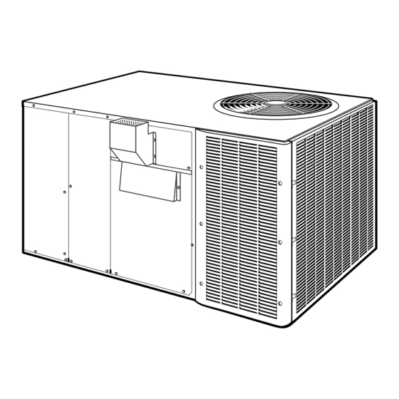
Single Package Gas/Electric
14 SEER Convertible
2 - 5 Ton
YCY-IOM-1E
18-EB21D7-6
11/12
Advertisement
Table of Contents

Related Manuals for American Standard YCY024G1L


Summary of Contents for American Standard YCY024G1L
- Page 1 National Electric Code -- ANSI/NFPA 70 or "LATEST REVISION." Since The Trane Companyhas a policy of continuous product and product data improvement, it reserves the right to change design and specification without notice. © 2003 American Standard Inc. All rights reserved 11/12...
-
Page 2: General Information
GENERAL INFORMATION IMPORTANT: Read this entire manual before IMPORTANT: DO NOT CONNECT GAS PIPING TO THE UNIT beginning installation procedures. UNTIL A LINE PRESSURE TEST HAS BEEN COMPLETED. ▲ DAMAGE TO THE GAS VALVE MAY RESULT IN AN UNSAFE WARNING: BODILY INJURY CAN RESULT FROM CONDITION. - Page 3 TYPICAL ROOFTOP INSTALLATION WITH FULL PERIMETER CURBS (YCY024-060G Models) FIELD SUPPLIED SUPPORTS AT EACH END OF CURB ROOFING ROOF INSULATION FIELD SUPPLIED CANT STRIP ROOF DECK FIELD SUPPLIED RIGID INSULATION ROOF MOUNTING CURB SUPPLY AIR RETURN AIR DUCT DUCT TYPICAL ROOFTOP INSTALLATION WITH BAYCURB030A (YCY024-060G Models) SEE NOTE 1 SEE NOTE 2...
-
Page 4: Dimensional Data
DIMENSIONAL DATA YCY024-060G OUTLINE – BACK CORNER WEIGHT (LBS) UNIT MODEL WEIGHT YCY024G-L 20-5/16 29-1/2 YCY024G-M 21-1/2 29-1/2 YCY030G-L 19-5/16 28-1/2 YCY030G-M 29-3/16 18-9/16 11-1/16 6-9/16 11-1/8 19-5/16 28-1/2 17-1/2 8-3/4 YCY036G-M 19-1/2 28-7/32 YCY036G-H 19-13/16 28-1/2 YCY042G-M 19-13/16 28-1/2 YCY048G-H 29-7/32 65-1/8... - Page 5 DIMENSIONAL DATA YCY024-060G OUTLINE – FRONT RECOMMENDED SERVICE CLEARANCE BACK * 6.0" CLEARANCE TO COMBUSTIBLE MATERIAL LEFT SIDE 30.0" BOTTOM 0.0" RIGHT SIDE 24.0" BACK 1.0" FRONT SIDE 42.0" LEFT SIDE 6.0" * 18" WITH FRESH AIR ACCESSORY RIGHT SIDE 6.0"...
- Page 6 CONVERTING HORIZONTAL TO DOWNFLOW HEATER EXCHANGER TUBES NOTE SUPPLY OPENING 1. REMOVE SCREW NEAREST TO THE OPENING AND PULL THE PANEL FIRMLY TOWARD THE OUTSIDE OF THE UNIT TO DISENGAGE THE BACK ATTACHMENT. RETURN OPENING 2. REMOVE RIGHT HAND SCREW AND MOVE PANEL TO THE RIGHT OR RE- MOVE BOTH SCREWS.
- Page 7 LOCATIONS AND RECOMMENDATIONS HORIZONTAL AIRFLOW APPLICATION 3. See the unit’s nameplate for the absolute minimum clearance between the unit and any combustible surface(s). 1. These units are design certified for outdoor installations. These IMPORTANT: units may be installed directly on wood flooring or on Class A, Class B, or Class C roof covering material.
-
Page 8: Installation
LOCATIONS AND RECOMMENDATIONS continued from page 7 15. Access and service clearances for the unit must be given Examine all flue product-carrying areas of the furnace, its vent careful consideration when locating the duct entrance open- system, and the main burner for safe operation. A periodic ings. - Page 9 INSTALLATION IMPORTANT: Do not lift the unit without test lifting for PLACING THE UNIT ON A MOUNTING CURB balance and rigging. Do not lift the unit in windy conditions or above personnel. Do not lift the unit by attaching a 1.
- Page 10 INSTALLATION ROOFTOP -- UNITS 4. Place the unit on the frame or roof curb. Refer to Figures 9 or For roof top applications using a field fabricated frame and ducts, use the following procedure: 5. Secure the unit to the frame or roof curb. 1.
-
Page 11: Condensate Drain Piping
INSTALLATION GROUND LEVEL -- HORIZONTAL UNITS For ground level installations, the unit should be positioned on a pad 2. Attach the supply and return air ducts to the unit. the size of the unit or larger. The unit must be level on the pad. The pad must not come in contact with the structure (See Figure 11.) Be 3. - Page 12 DUCTWORK ATTACHING DOWNFLOW DUCTWORK TO ROOF CURB ATTACHING HORIZONTAL DUCTWORK TO UNIT Supply and return air flanges are provided on the roof curb for easy All conditioned air ductwork should be insulated to minimize heating duct installation. All ductwork must be run and attached to the curb and cooling duct losses.
-
Page 13: Gas Piping Installation
GAS PIPING INSTALLATION IMPORTANT: Before making the gas pipe connection give NOTE: If this is an propane application, consult your propane serious consideration to providing the required clearance nec- supplier for pipe sizes and deliveries. essary to remove the access panels on the unit (e.g., economizer and filter access panels). - Page 14 GAS PIPING INSTALLATION NOTE: The shut-off gas cock must be installed outside of BURNER & VALVE ILLUSTRATION the unit and should meet the specifications of all appli- cable national and local codes. 2.Install a ground union joint downstream of the shut-off cock. This joint must also be installed outside of the unit.
- Page 15 GAS PIPING INSTALLATION INPUT CHECK AND ADJUSTMENT TABLE 3 GAS FLOW IN CUBIC FEET PER HOUR 1. Make sure all gas appliances are off except the furnace. 2 CUBIC FOOT DIAL Sec. Flow Sec. Flow Sec. Flow Sec. Flow 2. Clock the gas meter with the furnace operating (determine the dial rating of the meter) for one revolution.
-
Page 16: Filter Installation
FILTER INSTALLATION AIR FILTERS TABLE 4 NOMINAL FILTER* FILTER UNIT Filters are to be used with the YCY024-060G heating/cooling units. (Sq Ft) SIZE RESISTANCE The basic unit does not have filters in it. However, a filter frame YCY024F 2.67 0.05 accessory is offered that will allow filters to be installed within the unit. - Page 17 ELECTRICAL WIRING After all electrical wiring is complete, set the thermostat system the Thermostat System Switch until power has been applied long switch in the OFF position so that the compressor will not run enough to evaporate any liquid R-22 in the compressor. It is and then apply power by closing the system main disconnect recommended that the sump heater be energized for eight (8) hours switch.
- Page 18 START - UP PRE-START QUICK CHECKLIST NOTE: Do not use the pressures from the unit's SERVICE FACTS to determine the unit refrigerant charge. The correct charge is ● Is the unit properly located and level with the proper clearance? shown on the unit nameplate. To charge the system accurately, See Figure 4.
-
Page 19: Final Installation Checklist
START - UP 8. Set the thermostat at the desired temperature setting and the 6. Cycle the thermostat OFF and ON a few times at a rate of not unit will function automatically. more than once every thirty (30) seconds. Check both the control operation and the burner operating conditions. -
Page 20: Sequence Of Operation
SEQUENCE OF OPERATION Operation of the unit heating or cooling cycles is controlled by the temperature. If this device opens, the gas valve is immediately setting of the system switch on the room thermostat. Once the closed and will not permit operation until the limit switch closes. system switch is placed either in the “HEAT”... -
Page 21: Checkout Procedure
SELECTION SWITCHES LIGHT DIP SWITCHES (TYPICAL SETTINGS) CHECKOUT PROCEDURE TROUBLESHOOTING CHART SYSTEM FAULTS REFRIGERANT CIRCUIT Liquid Pressure Too high Liquid Pressure Too Low Suction Pressure Too High Suction Pressure Too Low Liquid Refrigerant floodback (TXV System) Liquid Refrig. floodback (Cap. Tube System) I. -
Page 22: Maintenance
MAINTENANCE ● ROUTINE MAINTENANCE BY OWNER Visually inspect the unit to ensure that the airflow required for combustion and condenser coil is not obstructed from the unit. You can do some of the periodic maintenance functions for your YCY-g unit yourself; this includes replacing the disposable or ●... -
Page 23: Limited Warranty
Models Less Than 20 Tons for Residential Use* (Parts Only) This limited warranty is extended by American Standard Inc., to the original purchaser and to any succeeding owner of the real property to which the Combination Gas Electric Air Conditioner is originally affixed, and applies to products purchased and retained for use within the U.S.A. - Page 24 Models Less Than 20 Tons for Commercial Use* (Parts Only) This warranty is extended by American Standard Inc., to the original purchaser and to any succeeding owner of the real property to which the Combination Gas Electric Air Conditioner is originally affixed, and applies to products purchased and retained for use within the U.S.A.