Table of Contents
Advertisement
INSTALLATION
OPERATION
MAINTENANCE
ALL phases of this installation must comply with
NATIONAL, STATE AND LOCAL CODES
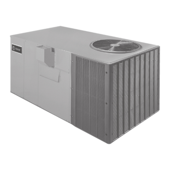
Model:
YCX024G1L-M
YCX030G1L-M
YCX036G1,3-L-M
YCX036G1,3,4-H
IMPORTANT — This Document is customer property and is to remain with this unit. Please return to service information pack upon completion of
work.
WARNING:
All phases of this installation must comply with the NATIONAL, STATE & LOCAL CODES. In the absence of local codes, the
installation must conform with National Electric Code -- ANSI/NFPA 70 or "LATEST REVISION."
Since The Trane Company has a policy of continuous product and product data
improvement, it reserves the right to change design and specification without notice.
© American Standard Inc. 2000
YCX042G1,3-M
YCX048G1,3,4-H
YCX060G1,3,4-M
BAYLIFT002A
LIFTING LUG KIT
HAZARDOUS VOLTAGE - DISCONNECT POWER BEFORE SERVICING
Single Package Gas/Electric
12 SEER Convertible
2 - 5 Ton
YCX-IOM-2A
18-EB21D5-2
Advertisement
Table of Contents

Related Manuals for American Standard YCX024G1L-M


Summary of Contents for American Standard YCX024G1L-M
- Page 1 National Electric Code -- ANSI/NFPA 70 or "LATEST REVISION." Since The Trane Company has a policy of continuous product and product data improvement, it reserves the right to change design and specification without notice. © American Standard Inc. 2000...
-
Page 2: General Information
GENERAL INFORMATION IMPORTANT: Read this entire manual before IMPORTANT: DO NOT CONNECT GAS PIPING TO THE UNIT beginning installation procedures. UNTIL A LINE PRESSURE TEST HAS BEEN COMPLETED. DAMAGE TO THE GAS VALVE MAY RESULT IN AN UNSAFE WARNING: BODILY INJURY CAN RESULT FROM CONDITION. - Page 3 TYPICAL ROOFTOP INSTALLATION WITH FULL PERIMETER CURBS (YCX024-036G-L/M Models on BAYCURB030/38A) FIELD SUPPLIED SUPPORTS AT EACH END OF CURB ROOFING ROOF INSULATION FIELD SUPPLIED CANT STRIP ROOF DECK FIELD SUPPLIED RIGID INSULATION ROOF MOUNTING CURB SUPPLY AIR RETURN AIR DUCT DUCT TYPICAL ROOFTOP INSTALLATION WITH BAYCURB030/38A (YCX036G-H;YCX042G-M;YCX048G-H;YCX060G-M)
-
Page 4: Dimensional Data
DIMENSIONAL DATA YCX024-060G OUTLINE –REAR Page 4... - Page 5 DIMENSIONAL DATA YCX024-060G OUTLINE – FRONT " 0 " 0 " 0 " 0 " 8 " 0 " 0 " 0 " 0 " 0 " 0 " 0 Page 5...
- Page 6 CONVERTING HORIZONTAL TO DOWNFLOW HEATER EXCHANGER TUBES NOTE SUPPLY OPENING 1. REMOVE SCREW NEAREST TO THE OPENING AND PULL THE PANEL FIRMLY TOWARD THE OUTSIDE OF THE UNIT TO DISENGAGE THE BACK ATTACHMENT. RETURN OPENING 2. REMOVE RIGHT HAND SCREW AND MOVE PANEL TO THE RIGHT OR RE- SHEET METAL HORIZONTAL RETURN...
- Page 7 LOCATIONS AND RECOMMENDATIONS HORIZONTAL AIRFLOW APPLICATION 3. See the unit’s nameplate for the absolute minimum clearance 1. These units are design certified for outdoor installations. These between the unit and any combustible surface(s). units may be installed directly on wood flooring or on Class A, Class B, or Class C roof covering material.
-
Page 8: Installation
LOCATIONS AND RECOMMENDATIONS 15. Access and service clearances for the unit must be given careful continued from page 7 consideration when locating the duct entrance openings. Fig- Examine all flue product-carrying areas of the furnace, its vent ure 4 provides unit dimensions. system, and the main burner for safe operation. - Page 9 INSTALLATION IMPORTANT: Do not lift the unit without test lifting for PLACING THE UNIT ON A MOUNTING CURB balance and rigging. Do not lift the unit in windy conditions or above personnel. Do not lift the unit by attaching a 1.
- Page 10 INSTALLATION ROOFTOP -- UNITS 4. Place the unit on the frame or roof curb. Refer to Figures 9 or For roof top applications using a field fabricated frame and ducts, use the following procedure: 5. Secure the unit to the frame or roof curb. 1.
-
Page 11: Condensate Drain Piping
INSTALLATION GROUND LEVEL -- HORIZONTAL UNITS For ground level installations, the unit should be positioned on a pad 2. Attach the supply and return air ducts to the unit. the size of the unit or larger. The unit must be level on the pad. The pad must not come in contact with the structure (See Figure 11.) Be 3. -
Page 12: Attaching Downflow Ductwork To Roof Curb
DUCTWORK ATTACHING DOWNFLOW DUCTWORK TO ROOF CURB ATTACHING HORIZONTAL DUCTWORK TO UNIT Supply and return air flanges are provided on the roof curb for easy All conditioned air ductwork should be insulated to minimize heating duct installation. All ductwork must be run and attached to the curb and cooling duct losses. -
Page 13: Gas Piping Installation
GAS PIPING INSTALLATION IMPORTANT: Before making the gas pipe connection give NOTE: If this is an LPG application, consult your LPG supplier serious consideration to providing the required clearance for pipe sizes and deliveries. necessary to remove the access panels on the unit (e.g., economizer and filter access panels). -
Page 14: Manifold Pressure
GAS PIPING INSTALLATION NOTE: The shut-off gas cock must be installed outside of the BURNER & VALVE ILLUSTRATION unit and should meet the specifications of all applicable national and local codes . COVER 2. Install a ground union joint downstream of the shut-off cock. ALTERNATE This joint must also be installed outside of the unit. -
Page 15: High Altitude Installation
FIRING RATE SELECTION b. Remove the slot screw on top of the gas valve for 1st stage All units are capable of firing at a low or high rate. Check the unit manifold pressure adjustment. Remove slot screw on outlet name-plate, to verify the firing rate of the unit as shipped from the side for 2nd stage adjustment (See Figure 17). -
Page 16: Filter Installation
FILTER INSTALLATION AIR FILTERS TABLE 4 Filters are to be used with the YCX024-060G heating/cooling units. The basic unit does not have filters in it. However, a filter frame - . t - . t - . t - . t - . -
Page 17: Thermostat Heat Anticipator
ELECTRICAL WIRING YCX-G FIELD WIRING DIAGRAM THERMOSTAT HEAT ANTICIPATOR The thermostat heat anticipators should be set to .4 amps on single After all electrical wiring is complete, set the thermostat system or two stage thermostats. switch in the OFF position so that the compressor will not run and then apply power by closing the system main disconnect IMPORTANT: Upon completion of wiring check all electrical switch. - Page 18 START - UP PRE-START QUICK CHECKLIST NOTE: Do not use the pressures from the unit's SERVICE FACTS to determine the unit refrigerant charge. The correct charge is Is the unit properly located and level with the proper clearance? shown on the unit nameplate. To charge the system accurately, See Figure 4.
-
Page 19: Final Installation Checklist
START - UP 8. Set the thermostat at the desired temperature setting and the 6. Cycle the thermostat OFF and ON a few times at a rate of not unit will function automatically. more than once every thirty (30) seconds. Check both the control operation and the burner operating conditions. -
Page 20: Sequence Of Operation
SEQUENCE OF OPERATION The setting of the system switch on the room Following this time period the valve is energized thermostat controls the operation of the unit heat- and the spark is started. If the flame is not sensed ing or cooling cycles. Once the system switch is by the flame detector (FD) within 7 seconds the placed either in the “HEAT”... -
Page 21: Checkout Procedure
CHECKOUT PROCEDURE TROUBLESHOOTING CHART SYSTEM FAULTS REFRIGERANT CIRCUIT Liquid Pressure Too high Liquid Pressure Too Low Suction Pressure Too High Suction Pressure Too Low Liquid Refrigerant floodback (TXV System) Liquid Refrig. floodback (Cap. Tube System) I. D. Coil Frosting Compressor Runs Inadequate or No Cooling ELECTRICAL Compressor &... -
Page 22: Maintenance
MAINTENANCE ROUTINE MAINTENANCE BY OWNER Visually inspect the unit to ensure that the airflow required for combustion and condenser coil is not obstructed from the unit. You can do some of the periodic maintenance functions for your YCX-G unit yourself; this includes replacing the disposable or Inspect the control panel wiring to verify that all electrical cleaning the permanent air filters, cleaning the unit cabinet, connections are tight and that the wire insulation is intact. -
Page 23: Limited Warranty
Models Less Than 20 Tons for Residential Use* (Parts Only) This warranty is extended by American Standard Inc., to the original purchaser and to any succeeding owner of the real property to which the Combination Gas Electric Air Conditioner is originally affixed, and applies to products purchased and retained for use within the U.S.A. - Page 24 Models Less Than 20 Tons for Commercial Use* (Parts Only) This warranty is extended by American Standard Inc., to the original purchaser and to any succeeding owner of the real property to which the Combination Gas Electric Air Conditioner is originally affixed, and applies to products purchased and retained for use within the U.S.A.