Table of Contents
Advertisement
Advertisement
Table of Contents

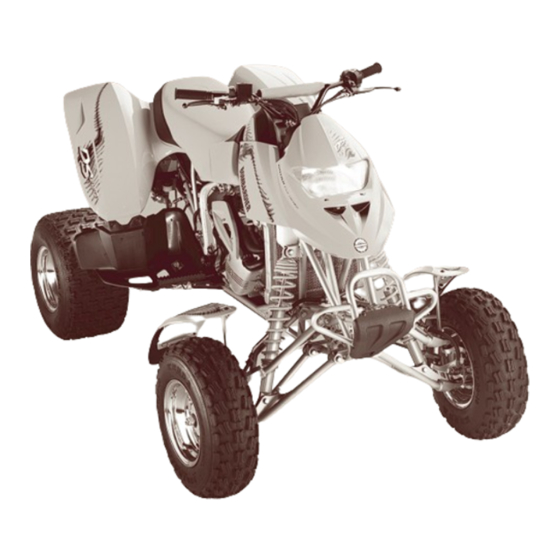
Summary of Contents for BOMBARDIER DS 650 2001
- Page 2 Shop Manual 2001 DS 650...
- Page 3 National Library of Quebec trimester 2000 National Library of Canada 2000 All rights reserved. No parts of this manual may be reproduced in any form without the prior written permission of Bombardier Inc. © Bombardier Inc. 2000 Technical Publications Bombardier Inc.
- Page 4 TABLE OF CONTENTS SECTION SUBSECTION PAGE SAFETY NOTICE ........................... WHAT’S NEW ............................INTRODUCTION ..........................SERVICE TOOLS AND 01 – Table of contents..............01-01-1 02 – Service tools................01-02-1 SERVICE PRODUCTS 03 – Service products............... 01-03-1 MAINTENANCE 01 – Table of contents..............02-01-1 02 –...
- Page 5 TABLE OF CONTENTS SECTION SUBSECTION PAGE TECHNICAL DATA 01 – SI metric information guide............11-01-1 02 – Engine and vehicle ..............11-02-1 WIRING DIAGRAM 01 – Wiring diagram................. 12-01-1 VMR2001_001_00_02A.FM...
- Page 6 The content depicts parts and/or procedures applicable to the particular product at its time of writing. Service and Warranty Bulletins may be published to update the content of this manual. Make sure to read and understand these. It does not include dealer modifications, whether authorized or not by Bombardier, after manufacturing the product.
-
Page 7: Cooling System
WHAT’S NEW WHAT’S NEW THIS SECTION INDICATES PROCEDURES THAT WERE MODIFIED OR NEWLY ADDED IN THIS MANUAL. INTRODUCTION • Self-locking fasteners procedure. • Loctite application procedure. SERVICE TOOLS AND PRODUCTS Added the following new tools: • ball joint guide • ball joint driver. Added the following new products: •... - Page 8 INTRODUCTION INTRODUCTION VEHICLE AND ENGINE SERIAL This Shop Manual covers the following Bombar- dier made 2001 ATV: NUMBER LOCATION Model DS* 650 ............. 7449 *Trademark of Bombardier Inc. V02A0PA V02A0QA 1. Model number 1. Vehicle 2. Engine VMR2001_001_00_02A.FM...
- Page 9 INTRODUCTION Serial Number Meaning SECTION 1 SECTION 2 SECTION 3 SECTION 4 10 11 12 13 14 15 16 17 SECTION 1 Class Make Manufacturer SECTION 2 Factory use Engine type II Engine type I Product line Type of drive SECTION 3 Check digit SECTION 4...
- Page 10 INTRODUCTION ARRANGEMENT OF THE inch MANUAL in² square inch The manual is divided into 12 major sections: in³ cubic inch kilo (thousand) 01 SERVICE TOOLS AND SERVICE PRODUCTS 02 MAINTENANCE kilogram 03 ENGINE km/h kilometer per hour 04 FUEL SYSTEM kilo pascal 05 ELECTRICAL liter...
-
Page 11: Cylinder And Head
INTRODUCTION This Shop Manual uses technical terms wich may be slightly different from the ones in the parts catalog. TYPICAL PAGE Page heading indicates section and subsection detailed. Section 03 ENGINE Subsection 05 (CYLINDER AND HEAD) CYLINDER AND HEAD Subsection title indicates beginning of the CYLINDER AND HEAD... - Page 12 INTRODUCTION TYPICAL PAGE Section 03 ENGINE Subsection 02 (REMOVAL AND INSTALLATION) – footrest (refer to BODY) Remove: Bold face number – engine pinion no. 2 (refer to Engine Pinion sec- – upper engine support bolt no. 11 tion) following part name –...
-
Page 13: General Information
Due to late changes, it may have some differences between the manufactured product and the descrip- tion and/or specifications in this document. Bombardier reserves the right at any time to dis- continue or change specifications, designs, fea- tures, models or equipment without incurring ob- ligation. - Page 14 INTRODUCTION Threadlocker 1. Clean threads (bolt and hole) with solvent. 2. Apply Loctite Primer N (P/N 293 800 041) on Uncovered Holes (bolts and nuts) threads (bolt and nut) and allow to dry for 30 seconds. 3. Choose proper strength Loctite threadlocker. 4.
- Page 15 INTRODUCTION Preassembled Parts NOTE: If it is difficult to readjust, heat screw with a soldering iron (232°C (450°F)). Stripped Thread Repair Stripped Threads A00A3OA 1. Apply here A00A3QA 2. Do not apply 1. Release agent 1. Clean bolts and nuts with solvent. 2.
- Page 16 INTRODUCTION Mounting on Shaft Case-In Components Mounting with a Press Metallic Gaskets A00A3VA A00A3UA 1. Bearing 1. Proper strength Loctite 2. Proper strength Loctite 3. Shaft 1. Clean inner housing diameter and outer gasket diameter. Standard 2. Spray housing and gasket with Loctite Primer N 1.
- Page 17 INTRODUCTION TIGHTENING TORQUES N•M FASTENER SIZE (8.8) LBF•FT Tighten fasteners to torque mentioned in explod- ed views and text. When they are not specified refer to following table.The table also gives the metric conversion. N•M FASTENER SIZE (8.8) LBF•IN VMR2001_001_00_02A.FM...
- Page 18 INTRODUCTION N•M FASTENER SIZE (8.8) LBF•FT N•M FASTENER SIZE (8.8) LBF•FT TIGHTENING TORQUES FOR 8.8 GRADE BOLTS AND NUTS VMR2001_001_00_02A.FM...
- Page 19 Page______ ❏ ❏ Machine___________________ Report of error Suggestion ____________________________________________________________ We would be pleased if you could ____________________________________________________________ communicate to Bombardier any sug- gestions you may have concerning our publications. ____________________________________________________________ ____________________________________________________________ ____________________________________________________________ ____________________________________________________________ Name ______________________________________________________ Address ____________________________________________________ City and State/Prov. ________________________...
- Page 20 AFFIX PROPER POSTAGE Technical Publications After Sales Service 565 de la Montagne Street Valcourt, Québec, Canada J0E 2L0 AFFIX PROPER POSTAGE Technical Publications After Sales Service 565 de la Montagne Street Valcourt, Québec, Canada J0E 2L0 AFFIX PROPER POSTAGE Technical Publications After Sales Service 565 de la Montagne Street Valcourt, Québec, Canada J0E 2L0...


