Table of Contents
Advertisement
Quick Links
GB
Operating manual
Betriebsanleitung ............p. 26
Mode d'emploi ................. p. 52
Airless high-pressure spraying unit
Airless Hochdruck-Spritzgerät
Groupe de projection à haute pression
Model 0290032 (PT4900)
Edition 2 / 2013
Ausgabe
D
F
PowrTwin Plus
Model 0290012 (PT4900)
0290013 (PT6900)
0290018 (PT8900)
0290016 (PT12000)
0290 935A
Advertisement
Table of Contents

Related Manuals for Titan PowrTwin Plus 0290032


Summary of Contents for Titan PowrTwin Plus 0290032
- Page 1 Operating manual Betriebsanleitung ....p. 26 Mode d’emploi ....p. 52 PowrTwin Plus Airless high-pressure spraying unit Airless Hochdruck-Spritzgerät Groupe de projection à haute pression Model 0290012 (PT4900) 0290013 (PT6900) 0290018 (PT8900) Model 0290032 (PT4900) 0290016 (PT12000) Edition 2 / 2013 0290 935A Ausgabe...
- Page 2 Before any work is done on the unit or for every break in work the following rules must be observed: 1. Release the pressure from spray gun and hose. 2. Secure the Titan spray gun using the safety catch on the trigger. 3. Switch o unit. Be safety conscious!
-
Page 3: Table Of Contents
Contents Contents Page Page Troubleshooting .................23 Safety regulations for Airless spraying ........2 Airless gun ....................23 Explanation of symbols used .............. 2 Fluid section ....................23 Electrical safety ..................3 Hydraulic motors ...................24 Gasoline engine safety ................4 Spray patterns ..................25 Fueling (gas engine) ................ -
Page 4: Safety Regulations For Airless Spraying
1MΩ. Titan high-pressure hoses. Danger of fire from solvent and paint fumes or bulging of cover. Check for damage or movement of couplings. -
Page 5: Electrical Safety
Safety precautions Electric Safety Electric models must be earthed. In the event of an electrical short sheet and technical information to ensure safe use. circuit, earthing reduces the risk of electric shock by providing an escape wire for the electric current. This product is equipped with a cord having an earthing wire with an appropriate earthing plug. -
Page 6: Gasoline Engine Safety
Safety precautions Gasoline Engine Safety Fueling (gas engine) 1. Gas engines are designed to give safe and dependable service if operated according to instructions. Read and understand Gasoline is extremely flammable and is explosive under certain conditions. the engine. Failure to do so could result in personal injury or equipment damage. -
Page 7: General View Of Application
General view of application Description of unit General view of application Description of unit Application Airless process Priming and nal coating of large areas, sealing, impregnation, The main area of application are thick layers of highly viscous coating construction sanitation, façade protection and renovation, rust material for large areas and a high consumption of material. -
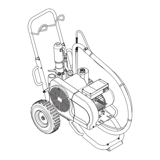
Page 8: System Diagram - Gasoline Pt Units
Description of unit System diagram - gasoline PT units 1 Extractable handle 7 High-pressure hose outlet 2 Hydraulic motor 8 V-belt under the belt cover 3 Oil cup for separating oil (separating oil prevents increased 9 Bleed hose wear and tear of the packings) 10 Ball valve: horizontal position –... -
Page 9: System Diagram - Electric Pt Units
Description of unit System diagram - electric PT units 1 Extractable handle 9 Bleed hose 2 Hydraulic motor 10 Ball valve: horizontal position – hydraulic motor switched o 3 Oil cup for separating oil (separating oil prevents increased vertical position – hydraulic motor switched on wear and tear of the packings) 11 Suction tube 4 Pressure control knob... -
Page 10: Technical Data For Pt Units
Description of unit Technical data for PT units PT4900 Plus PT4900 Plus PT6900 Plus PT8900 Plus PT12000 Plus (230V) (gas) Gasoline engine, power Subaru -------- 169cc, 5.7 Hp -------- -------- -------- Honda -------- -------- 163cc, 4.8 Hp 196cc, 5.5 Hp 270cc, 8.5 Hp Fuel Capacity --------... -
Page 11: Operation
Refer to the Maintenance section of this manual for hydraulic system maintenance instructions. Use of Titan’s Coolflo™ Hydraulic Fluid (P/N 430-361) is mandatory in the hydraulic system. Do not use any other hydraulic fluid. Use of any other hydraulic... -
Page 12: Preparing A New Sprayer
Operation 9. Turn o the sprayer. Preparing a New Sprayer To turn o the gas engine, If this unit is new, it is shipped with test uid in the uid section to prevent corrosion during shipment and storage. This uid must be knob fully counterclockwise, thoroughly cleaned out of the system with mineral spirits before you begin spraying. -
Page 13: Preparing To Paint
Operation 6. Start the engine or turn on the electric motor. Make sure that the spray gun does not have a tip or To start the gas engine ( g. 8), tip guard installed. 10. Close the bleed valve by turning it fully clockwise. 11. -
Page 14: Pressure Relief Procedure
Operation Cleanup Cleanup Pressure Relief Procedure Be sure to follow the Pressure Relief Procedure when The sprayer, hose, and gun should be cleaned thoroughly after daily use. Failure to do so permits shutting the unit down for any purpose, including material to build up, seriously a ecting the servicing or adjusting any part of the spray system, performance of the unit. -
Page 15: Cleaning A Clogged Tip
Cleanup Maintenance 12. Start the engine or turn on the electric motor. Maintenance Earth the gun by holding it against the edge of the Before proceeding, follow the Pressure Relief metal container while flushing. Failure to do so may Procedure outlined previously in this manual. lead to a static electric discharge, which may cause Additionally, follow all other warnings to reduce the a fire. -
Page 16: Maintaining The Lter Assembly
Maintenance Reassembly (Fig. 15) Maintaining the Filter Assembly After cleaning and inspecting all parts, reassemble the lter. Clean the lter regularly. Dirty or clogged lters can greatly reduce 1. Place the carbide seat (6) into the lter body (4). Make sure ltering ability and cause a number of system problems including the beveled side of the seat is facing up. -
Page 17: Maintaining The Hydraulic System
Basic Engine Maintenance (gas engine) Maintaining the Hydraulic System refer to the separate gasoline engine manual. Use of Titan’s Coolflo™ Hydraulic Fluid is mandatory in the PowrTwin Plus hydraulic system. Do not use any other hydraulic fluid. Use of any other hydraulic authorized by the engine manufacturer. -
Page 18: Replacing The Motor Brushes (120V Electric Convertokit)
Maintenance Replacing the Motor Brushes (optional 120V electric motor) The 120V electric Convertokit is available for separate purchase. consists of two brushes, two springs, and two clips. Brushes should be replaced when they are worn to less than 1/2 inch. Check and replace both brushes at the same time. -
Page 19: Replacing The Belt
Maintenance Replacing the Belt (Fig. 21) 3. While the gas engine / electric motor is lifted up, remove the Before replacing the belt on your unit, make sure belt from the front (4) and rear (5) pulleys. you have performed the “Pressure Relief Procedure” 4. -
Page 20: Servicing The Hydraulic Motor
Maintenance Servicing the Hydraulic Motor (Fig. 22) Refer to the ”SAE O-Ring Fitting Installation” procedure at the end of this section for installation instructions for item 22. Perform this procedure using the necessary parts from Motor Service the machine and jog the piston rod (19) into its top position. Servicing of the hydraulic motor should be carried out in a clean, dust free area only. - Page 21 Maintenance 13. Remove piston seal (16) and o-ring (17). rod pass through the top of the spool/sleeve set (10). The valve rod threads must be clean and free of oil. Place one drop 14. Remove trip retainers (4), trip springs (6), and balls (7) from cylinder head (8).
-
Page 22: Servicing The Uid Section
Disassembling the Fluid Section Use of non-Titan service parts may void warranty. Ask for original parts made by Titan for best services. housing (20,21) and the pump cylinder (14) with a strap This pump should receive a routine servicing after wrench. - Page 23 Maintenance Reassembling the Fluid Section It is not necessary to over-tighten the foot valve housing. O-ring seals perform sealing function without excessive tightening. Full thread Use Te on tape on all threaded pipe connections. engagement is sufficient. The foot valve housing may be rotated backward up to 1/2 turn from full 1.
-
Page 24: Sae O-Ring Tting Installation
Maintenance 6.10 SAE O-Ring Fitting Installation 1. Pull washer and o-ring back as far as possible. 3. Screw tting in until washer pushes o-ring into entrance and 4. Back tting out no more than one complete turn to align as required. -
Page 25: Troubleshooting
Troubleshooting Troubleshooting Airless Gun Problem Cause Solution Spitting gun Air in system Inspect connections for air leaks. Dirty gun Disassemble and clean. Inspect and adjust. Broken or chipped seat Inspect and replace. Gun will not shut o Worn or broken needle & seat Replace. -
Page 26: Hydraulic Motors
Troubleshooting Hydraulic Motors Problem Cause Solution Oil motor stalls at bottom (no Fluid pump piston seat unthreaded If connecting rod is okay, remove cylinder head plug unusual heat problems) and pop valve down. Replace plug and start machine. If machine cycles up and stops at bottom again, then problem is piston seat on uid pump. -
Page 27: Spray Patterns
Troubleshooting Spray Patterns Problem Cause Solution Tails Inadequate uid delivery Fluid not atomizing correctly: Increase uid pressure. Change to smaller tip ori ce size. Reduce uid viscosity. Reduce hose length. Clean gun and lter(s). Reduce number of guns using pump. Same as above. - Page 28 Spare parts diagram Ersatzteilbild Illustration des pièces de rechange Main Assembly Hauptbaugruppe Ensemble principal PowrTwin Plus...
-
Page 29: Pt6900 Pt8900 Pt12000
PT4900 PT4900 PT6900 PT8900 PT12000 Pos. (230V) Plus Plus Plus Plus Description Benennung Description 235-117A 235-117A 235-118A 236-154A 236-154A Motor / pump assembly Motoren-/ Bloc moteur/pompe Pumpenbaugruppe 703-137A 703-137A 703-137A 703-137A 703-137A Swivel tting assembly Drehlageraufbau ------- ------- ------- ------- ------- Bleed hose assembly Baugruppe der... - Page 30 Spare parts diagram Ersatzteilbild Illustration des pièces de rechange Cart Assembly Wagenbaugruppe Ensemble de chariot PowrTwin Plus...
- Page 31 PT4900 PT4900 PT6900 PT8900 PT12000 Pos. (230V) Plus Plus Plus Plus Description Benennung Description 0290444 0290444 0290444 0290444 0290444 Handle Deichsel 449-055 449-055 459-051 459-051 459-051 Motor/pump bracket Motor-/Pumpenträger Support du moteur/de la pompe 862-460 862-460 862-460 862-460 862-460 Screw Schraube 0290581 0290581...
- Page 32 Spare parts diagram Ersatzteilbild Illustration des pièces de rechange Hydraulic System Hydrauliksystem Système hydraulique PowrTwin Plus...
- Page 33 PT4900 PT4900 PT6900 PT8900 PT12000 Pos. (230V) Plus Plus Plus Plus Description Benennung Description 313-755 313-755 313-755 313-755 313-755 Aufkleber Etiquette 862-414 862-414 862-414 862-414 862-414 Set screw Sicherungsschraube Vis de blocage 448-243 448-243 448-243 448-243 448-243 Pressure control knob Druckregulierknopf pression 449-751...
- Page 34 Spare parts diagram Ersatzteilbild Illustration des pièces de rechange Hydraulic Motor Hydraulikmotor Moteur hydraulique PowrTwin Plus...
- Page 35 PT4900 PT4900 PT6900 PT8900 PT12000 Pos. (230V) Plus Plus Plus Plus Description Benennung Description 235-030 235-030 235-030 235-030 235-030 Cylinder head plug Fiche de la tête du cylindre 441-217 441-217 441-217 441-217 441-217 O-ring O-ring Joint torique 858-811 858-811 858-811 858-811 858-811 Flex lock nut...
- Page 36 Spare parts diagram Ersatzteilbild Illustration des pièces de rechange Fluid Section Flüssigkeitsbereich Section des liquides PT4900 Plus PowrTwin Plus...
- Page 37 PT4900 PT4900 Pos. (230V) Plus Description Benennung Description 143-019 143-019 Retaining ring Spiralring 107-003 107-003 Connecting pin Verbindungsstift Goupille de liaison 106-015 106-015 O-ring, Te on (2) O-ring, Te on (2) 106-002A 106-002A Polyethylen/Stahl (2) 106-005 106-005 107-029 107-029 Displacement rod Tige de piston 106-001 106-001...
- Page 38 Spare parts diagram Ersatzteilbild Illustration des pièces de rechange Fluid Section Flüssigkeitsbereich Section des liquides PT6900 Plus PT8900 Plus PT12000 Plus PowrTwin Plus...
- Page 39 Pos. PT6900 PT8900 PT12000 Description Benennung Description 143-019 143-019 143-019 Retaining ring Spiralring 143-120 143-120 143-120 Connecting pin Verbindungsstift Goupille de liaison 145-031 145-031 145-031 O-ring, Te on (2) O-ring, Te on (2) 138-153A 138-153A 138-153A steel (2) Polyethylen/Stahl (2) 142-004 142-004 142-004...
- Page 40 Spare parts diagram Ersatzteilbild Illustration des pièces de rechange Gas Convertokit Convertokit, Benzinmotor Convertokit à essence PT4900 Plus PT12000 Plus PT6900 Plus PT8900 Plus PT4900 PT6900 PT8900 Pos. Plus Plus Plus Description Benennung Description 860-502 860-502 860-502 Stop nut (8) Stellmutter (8) 860-004 860-004...
- Page 41 Spare parts diagram Ersatzteilbild Illustration des pièces de rechange DC - Electric Convertokit (230V) Convertokit, Elektromotor (230V) Convertokit, moteur électrique (230V) PT4900 Pos. (230V) Description Benennung Description 9805427 Screw (2) Schraube (2) Vis (2) 860-004 Flat washer (12) Schiebe (12) Rondelle (12) 0349592 Motor, DC-Electric, 3 Hp, 50 Hz, 230V...
- Page 42 Spare parts diagram Ersatzteilbild Illustration des pièces de rechange High Pressure Filter Hochdruck lter Filtre à haute pression Filter Assembly Speci cations Maximum Working Pressure ..5000 psi (34.5 MPa) Filter Area ......... 18 In (116 cm Outlet Ports ........Wetted Parts ........
- Page 43 Spare parts diagram Ersatzteilbild Illustration des pièces de rechange Belt Guard Assembly Keilriemenbaugruppe Protège-courroie PT4900 PT4900 PT6900 PT8900 PT12000 Pos. (230V) Plus Plus Plus Plus Description Benennung Description 0290628A 0290628A 0290628A 0290628A 0290628A Belt guard, rear Riemenschutz, hinten Protège-courroie, derrière 9805415 9805415 9805415...
- Page 44 Spare parts diagram Ersatzteilbild Illustration des pièces de rechange Bleed Hose Assembly with Valve Ablassschlauchbaugruppe mit Ventil Assemblage du tuyau de décharge avec soupape PT4900 PT4900 PT6900 PT8900 PT12000 Pos. (230V) Plus Plus Plus Plus Description Benennung Description 944-030A 944-030A 944-030A 944-030A 944-030A...
- Page 45 Spare parts diagram Ersatzteilbild Illustration des pièces de rechange Bleed Valve Assembly Ablassschlauchbaugruppe Assemblage de la soupape de décharge PT4900 PT4900 PT6900 PT8900 PT12000 Pos. (230V) Plus Plus Plus Plus Description Benennung Description 944-047 944-047 944-047 944-047 944-047 Hex screw Sechskantschraube Vis hexagonale 944-029...
- Page 46 Spare parts diagram Ersatzteilbild Illustration des pièces de rechange Siphon Hose Assembly Syphonschlauchbaugruppe Assemblage du tuyau de siphon PT4900 PT4900 PT6900 PT8900 PT12000 Pos. (230V) Plus Plus Plus Plus Description Benennung Description 316-502 316-502 316-502 316-502 316-502 Hose Schlauch Tuyau 103-679 103-679 103-679...
-
Page 47: Connection Diagram (230V)
Spare parts diagram Ersatzteilbild Illustration des pièces de rechange Connection Diagram (230V) Schaltplan (230V) Schéma électrique (230V) Accessories for PT units Zubehör für PT-Geräte Accessoires pour groupes PT DC - Electric Convertokit (120V) Convertokit, Elektromotor (120V) Convertokit, moteur électrique (120V) PT4900 Pos. - Page 48 Accessories for PT units Zubehör für PT-Geräte Accessoires pour groupes PT Description Benennung Description 103-826 5 Gal. Siphon Hose Assembly w/Rock 5 Gal. Saugschlauch w/Steinabschneider 1” roches de 2,5 cm x 1,4 m 0509762A 55 Gal. Siphon Hose Assembly w/Rock 55 Gal.
-
Page 49: Gun Manifold Assemblies (Optional)
Gun Manifold Assemblies (Optional) Pistolenmehrfachanschluss (Optional) Ensembles de collecteur de pistolet (facultatifs) 1-Gun add-on Add-A-Gun Kit 1-Pistolenerweiterung Kit zur Pistolenerweiterung Pistolet simple additionnel Trousse pour ajouter un pistolet 975-111 975-311 975-200 975-300 (1/4” / 6,35 (3/8” / 9,53 (1/4” / 6,35 (3/8”...