Table of Contents
Advertisement
Quick Links
Download this manual
See also:
Instruction Manual
QQ
3 7 63 1515 0
TE
L 13942296513
www
.
http://www.xiaoyu163.com
SERVICE MANUAL
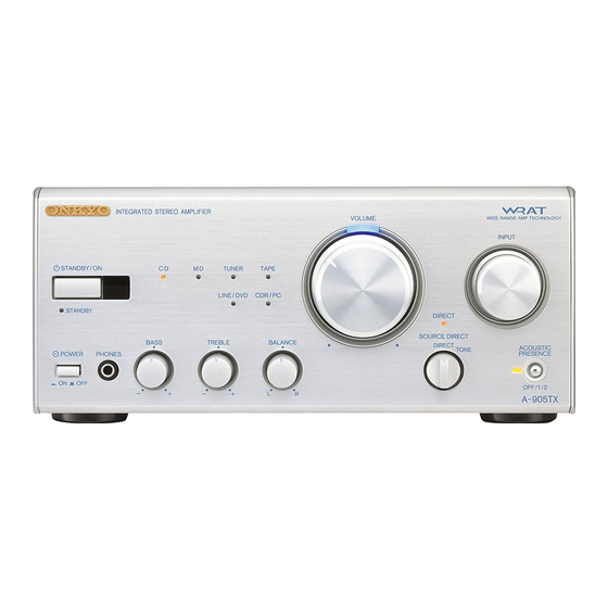
INTEGRATED STEREO AMPLIFIER
A-905TX
INTEGRATED STEREO AMPLIFIER
CD
MD
TUNER
TAPE
STANDBY/ON
LINE/ DVD
CDR/PC
STANDBY
BASS
TREBLE
BALANCE
POWER
PHONES
ON
OFF
—
+
—
+
L
UDT
120V AC, 60Hz
UPT
230-240V AC, 50Hz
SAFETY-RELATED COMPONENT
WARNING!!
COMPONENTS IDENTIFIED BY MARK
SCHEMATIC DIAGRAM AND IN THE PARTS LIST ARE
CRITICAL FOR RISK OF FIRE AND ELECTRIC SHOCK.
REPLACE THESE COMPONENTS WITH ONKYO
PARTS WHOSE PART NUMBERS APPEAR AS SHOWN
IN THIS MANUAL.
MAKE LEAKAGE-CURRENT OR RESISTANCE
MEASUREMENTS TO DETERMINE THAT EXPOSED
PARTS ARE ACCEPTABLY INSULATED FROM THE
SUPPLY CIRCUIT BEFORE RETURNING THE
APPLIANCE TO THE CUSTOMER.
x
ao
u163
y
i
2 9
8
VOLUME
WIDE RANGE AMP TECHNOLOGY
INPUT
DIRECT
SOURCE DIRECT
DIRECT
ACOUSTIC
PRESENCE
TONE
OFF /1/ 2
R
A-905TX
Q Q
3
6 7
1 3
1 5
ON THE
co
.
A-905TX
9 4
2 8
Ref. No. 3677
052001
STANDBY/ ON
GRAPHIC EQ
CLOCK
SLEEP
EFFECT
MODE
TUNER
INPUT
PRESET
F M
A M
TAPE
PAUSE / STEP
DVD
M D
REPEAT
SCROLL
PLAY MODE
CLEAR
REC
REPEAT
RANDOM
C D
MEMORY
CLEAR
DISC
CDR
REPEAT
PLAY MODE
TONE
CLEAR
REC
MUTING
1
2
3
TIMER
4
5
6
UP/DOWN
7
8
9
VOLUME
ACOUSTIC
PRESENCE
- - / - - -
10 / 0
ENTER
REMOTE CONTROLLER
RC - 456 S
0 5
8
2 9
9 4
2 8
m
9 9
9 9
Advertisement
Table of Contents

Related Manuals for Onkyo A-905TX


Summary of Contents for Onkyo A-905TX
-
Page 1: Service Manual
COMPONENTS IDENTIFIED BY MARK ON THE SCHEMATIC DIAGRAM AND IN THE PARTS LIST ARE CRITICAL FOR RISK OF FIRE AND ELECTRIC SHOCK. REPLACE THESE COMPONENTS WITH ONKYO PARTS WHOSE PART NUMBERS APPEAR AS SHOWN IN THIS MANUAL. MAKE LEAKAGE-CURRENT OR RESISTANCE... -
Page 2: Specifications
A-905TX 3 7 63 1515 0 SPECIFICATIONS PART-XX L 13942296513 SERVICE PROCEDURES PART-XX Replacing the fuses DESCRIPTION This symbol located near the fuse indicates that the REF.NO. PART NO. fuse used is show operating type, For continued protection against... -
Page 3: Chassis Exploded View
A-905TX http://www.xiaoyu163.com 3 7 6 3 1 5 1 5 0 CHASSIS EXPLODED VIEW ############ P901 P402 P402 P584A P701 P801 Q527 Q525 Q523 L 1 3 9 4 2 2 9 6 5 1 3 Q524 Q526 Q528 F901... -
Page 4: Chassis Exploded View Parts List
A-905TX 3 7 6 3 1 5 1 5 0 CHASSIS EXPLODED VIEW PARTS LIST ############ REF NO. PART NO. DESCRIPTION REF NO. PART NO. DESCRIPTION 27111123 Front bracket P402 27190011 KGLS-6S, Holder 838130088 3TTB+8B, Self tapping screw P584A 880009 Plastic rivet, NRP-345 <PT>... - Page 5 A-905TX 3 7 6 3 1 5 1 5 0 SCHEMATIC DIAGRAM-1 TO NAAF-6631 P405B P405C NADG-6630 Acoustic Presence AMP&VR R551 SUBWOOFER PREOUT R543 (1/2W) P582 24.6 (1/2W) 24.1 Q523 Q519 P307 Q301 Q531 R351 R353 2SA965 2SC4512 R581...
- Page 6 A-905TX 3 7 6 3 1 5 1 5 0 SCHEMATIC DIAGRAM-2 Tone bass NAAF-6631 NJM4565D-D ACOUSTIC PRESENCE C403 R401 R407 Q409 3.3K 2SK246 C407 (1/2) R523 47/50 Q401 R505 R507 R527 R531 47/50 R409 R421 1.8K 1.8K D405...
- Page 7 A-905TX 3 7 6 3 1 5 1 5 0 PC BOARD CONNECTION DIAGRAM XXXXX SPEAKERS SUBWOOFER PROCESSOR CDR/PC REMOTE TAPE LINE/DVD PRE OUT PLAY REC PLAY CONTROL PLAY REC TUNER NAETC-6636 P582 P303 P302 P301 P307 P306 P305...
-
Page 8: Printed Circuit Board Parts List
A-905TX 3 7 63 1515 0 PRINTED CIRCUIT BOARD PARTS LIST-1 MAIN CIRCUIT PC BOARD (NADG-6630-4B/C) CIRCUIT NO. PART NO. DESCRIPTION CIRCUIT NO. PART NO. DESCRIPTION R563,R564 453530474 4.7ohm +/-5%, 1/2W, Metal oxide R565,R566 453530824 8.2ohm +/-5%, 1/2W, Metal oxide... - Page 9 A-905TX 3 7 63 1515 0 PRINTED CIRCUIT BOARD PARTS LIST-2 ACOUSTIC CIRCUIT PC BOARD (NAAF-6632-4B/C) CIRCUIT NO. PART NO. DESCRIPTION CIRCUIT NO. PART NO. DESCRIPTION Capacitors C746 353721019 100uF0, 6.3V, Elect. Q401 22240191 NJM4565D-D C714,C715 353741009 10uF, 16V, Elect.
- Page 10 A-905TX MICROPROCESSOR TERMINAL DESCRIPTION 3 7 63 1515 0 Q701:HD404316-E30H Pin No. Function Descriptions TEST Test pin. RESET System reset input pin. OSC1 Pins to connect the ceramic oscillator 4.0MHz. OSC2 Ground pin. AVSS Analog reference ground for A/D converter.
-
Page 11: Microprocessor Connection Diagram
A-905TX 3 7 6 3 1 5 1 5 0 MICROPROCESSOR CONNECTION DIAGRAM Q701:HD404316E04H ACOUSTIC PRESENCE INDICATOR SOURCE INDICATOR DRIVER GREEN Q707 74HC595 PROTECTER DETECTOR CIRCUIT INPUT SELECTOR Q301 TC9273N-010 ACOUSTIC PRESENCE CIRCUIT SBASS-3 TEST SYSTEM RESET RESET SBASS-2... - Page 12 A-905TX ADJUSTMENT PROCEDUERS 3 7 63 1515 0 IDLING CURRENT ADJUSTMENT 1. Before Idling adjustment, turn the trimming resistors R575, R576 to counter clockwise. 2. Connect the DC voltmeter to terminal P503, P504. 3. After turn POWER to ON, adjust the trimming resistors R575, R576 so that the reading of voltmeter becomes 2.0 mV.
- Page 13 A-905TX 3 7 63 1515 0 OOOOOOO PAD ASSEMBLY PROCEDURES-1 ############ ASSEMBLING OF PAD A Procedures : 1 to 5 : Line shows folding direction : Line shows folding direction Pin mark side Pin mark L 13942296513 Other side u163 http://www.xiaoyu163.com...
- Page 14 A-905TX 3 7 63 1515 0 OOOOOOO PAD ASSEMBLY PROCEDURES-2 ############ ASSEMBLING OF PAD B Procedures : 1 to 5 : Line shows folding direction Pin mark side Pin mark L 13942296513 Other side u163 http://www.xiaoyu163.com...
- Page 15 A-905TX 3 7 63 1515 0 OOOOOOO PAD ASSEMBLY PROCEDURES-3 ############ INSERT PAD A TO PAD B Pad A Pad B L 13942296513 u163 http://www.xiaoyu163.com...
-
Page 16: Packing View
A-905TX 3 7 63 1515 0 PACKING VIEW PART-XX Bottom side Bottom side L 13942296513 PARTS LIST REF NO. PART NO. DESCRIPTION 29091886 Pad A 29091887 Pad B 29095835 Protection sheet 0.515*650*550 29110149 Tape 282301 Staple 29110141 Tape 29053720... - Page 17 Sales & Product Planning Div. : 2-1, Nisshin-cho, Neyagawa-shi, OSAKA 572-8540, JAPAN Tel: 072-831-8111 Fax: 072-833-5222 ONKYO U.S.A. CORPORATION 18 Park Way, Upper Saddle River, N.J. 07458, U.S.A. Tel: 201-785-2600 Fax: 201-785-2650 E-mail: onkyo@onkyousa.com ONKYO EUROPE ELECTRONICS GmbH Industriestrasse 20, 82110 Germering, GERMANY Tel: 089-849-320 Fax: 089-849-3265 E-mail: info@onkyo.de...