Advertisement
Quick Links
,1_ 2006 Lennox industries
Inc.
Dallas, Texas, USA
INSTALLATION
INSTRUCTIONS
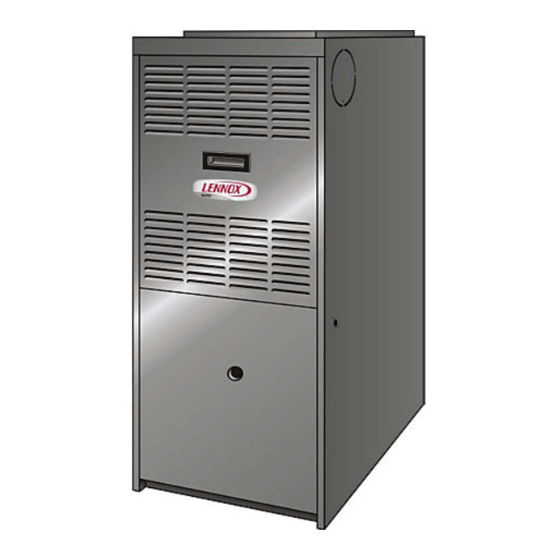
G50UH(X) Series
GAS FURNACE
505,254M
_
Technical
8/2006
.L_ ._L Publications
Supersedes 504,957M
Lithe U.S.A.
RETAIN THESE
INSTRUCTIONS
FOR FUTURE
REFERENCE
Unit Dimensions
................................
2
G50UH(X) Parts Arrangement
....................
3
G50UH(X) Gas Furnace ..........................
4
Shipping and Packing List ........................
4
Safety Information ...............................
4
General ........................................
5
Combustion, Dilution & Ventilation Air ..............
6
Setting Equipment ...............................
8
Filters ..........................................
12
Duct System ....................................
12
Venting
........................................
12
Gas Piping .....................................
20
Electrical .......................................
21
Unit Start-Up
...................................
25
Gas Pressure Adjustment
........................
26
High Altitude Information
.........................
27
Other Unit Adjustments
..........................
27
Service
........................................
28
Repair Parts List ................................
30
Ignition Control Board Diagnostic Codes
...........
30
Troubleshooting
.................................
31
Start-Up & Performance Check List ................
35
&WARNING
Do not store or use gasoline or other
flammable
vapors and liquids
in the
vicinity
of this
or any
other
ap-
pliance.
Installation
and
service
must
be
performed
by a qualified
installer,
service
agency
or the gas supplier.
WHAT TO DO IF YOU SMELL GAS:
• Do not try to light any appliance.
• Do not touch any electrical
switch;
do not
use any phone in your building.
• Leave the building
immediately.
• Immediately
call your gas supplier
from a
neighbor's
phone. Follow the gas supplier's
instructions.
• If you cannot
reach your gas supplier,
call
the fire department.
08/06
IIIHIININIIIIIIIIIIIIIIIIIIIIIIIIIIII
Page1
505,254M
IIIHIIIIIIIIIIIIIIIIIIINII
Advertisement

Related Manuals for Lennox G50UH-24A-045


Summary of Contents for Lennox G50UH-24A-045
- Page 1 G50UH(X) Series GAS FURNACE 505,254M 8/2006 Supersedes 504,957M Unit Dimensions G50UH(X) Parts Arrangement G50UH(X) Gas Furnace ... Shipping and Packing List ... Safety Information ... General ... Combustion, Dilution & Ventilation Air ... Setting Equipment ... Filters ... Duct System ...
- Page 2 4. Return air from both sides. 5. Bottom and one side return air. See Blower Performance Tables for additional information. 2 Flue outlet may be horizontal but furnace must be vented vertically 3 Optional External Side Return Air Filter Kit is not for use with the optional RAB Return Air Base.
- Page 3 Gasket FlueTransition Flame Sensor _ Flame Rollout Switches* Flame Rollout Bracket Gas Valve Gas Orifices Ignitor Bracket Burner Bottom Shield Control Transformer SureLight ¢ Control Board _'_ "135 and 155 kBtuh units only -- Flame rollout switches are located on brackets on the inner sides (one on the left and one on the right) of the burner box.
- Page 4 This G50UH(X) furnace must be installed so that its electri- cal components are protected from water. When this furnace is used with cooling units, it shall be installed in parallel with, or on the upstream side of, cooling units to avoid condensation in the heating compartment.
- Page 5 In addition to the requirements outlined previously, the fol- lowing general when installing a G50UH(X) furnace: • Place the furnace as close to the center of the air dis- tribution system as possible. The furnace should also be located close to the chimney or vent termination point.
- Page 6 If the furnace is located in a building of tight construction with weather stripping and caulking around the windows and doors, follow the procedures in the air from outside section.
- Page 7 100 square inches (64516 mm2). FIGURE 2 Air from Inside If the confined space that houses the furnace adjoins a space categorized as unconfined, air can be brought in by providing two permanent openings spaces.
- Page 8 Floor *Front clearance Maintain a minimum of 24 in. (610 ram) for front service access. SFor installation on a combustible floor, do not install the furnace directly on carpeting, than wood flooring. l-Left side requires 3 inches ifa single wall vent is used on 14-1/2 inch cabinets, or 2 inches if a single wall vent is used on 17-1/2 inch cabinets.
-
Page 9: Front View
The furnace is equipped with a removable panel to facilitate installation, Markings are provided on both sides of the furnace cabinet for installations that require side return air. Cut the furnace cabinet at the maximum dimensions NOTE - When air volumes... - Page 10 5/16 inch machine bolts (4) and nuts (8), See figure 10. NOTE - The maximum length of the bolt is 1-1/2 inches. 1 - Lie the furnace on its back and drill a 5/16 inch diame- ter hole in each corner of the furnace's bottom. See fig-...
- Page 11 Cooling coils and supply and return air plenums must be supported separately. NOTE - When the furnace is installed on a platform in a crawlspace, it must be elevated enough to avoid water damage and to allow the evaporator coil to drain.
- Page 12 In upflow applications, the return air can be brought in through the bottom or either side of the furnace. If a fur- nace with bottom return air is installed on a platform, make an airtight seal between the bottom of the furnace and the...
-
Page 13: Vent Connection
NOTE - Use these instructions as a guide. They do not su- persede local codes. This furnace must be vented accord- ing to all local codes these installation instructions, and the provided venting tables in these instructions The venting tables in this manual were extracted from the National Fuel Gas Code (NFPA 54 / ANSI Z223.1 ) and are... - Page 14 Refer to the capacity requirements vided venting tables for installations ,IMPORTANT A fan-assisted furnace may be commonly vented into an existing lined masonry chimney if the following conditions are met: • The chimney is currently serving at least one drafthood equipped appliance •...
- Page 15 1/4 inch (6.4 mm) per linear foot (305 mm) of connector, back toward the appliance. 11 - Vent connectors shall be firmly attached to the furnace flue collar by self-drilling screws or other approved means, except vent connectors of listed type B vent...
- Page 16 Capacity of Type B Double-Wall Height Lateral 3 Inch (feet) (feet) NOTE - Single appliance venting configurations with zero lateral lengths are assumed to have no elbows in the vent system. For all other vent configurations, the vent system is assumed to have two 90 ° elbows. For each additional 90 ° elbow or equivalent (for example two 45 ° elbows equal one 90 °...
- Page 17 Capacity of Type B Double-Wall Height Lateral 3 Inch (feet) (feet) NOTE - Single appliance venting configurations with zero lateral lengths are assumed to have no elbows in the vent system. For all other vent configurations, the vent system is assumed to have two 90 ° elbows. For each additional 90 ° elbow or equivalent (for example two 45 ° elbows equal one 90 °...
- Page 18 Type B Double-Wall Serving Vent Connector Height Rise 3 Inch (feet) (feet) Type B Double-Wall Serving Vent Height 4 Inch (feet) FAN + FAN FAN + NAT TABLE 5 Vent Connector Capacity Vents with Type B Double-Wall Connectors Two or More Category I Appliances Vent and Connector Diameter - D (inches)
- Page 19 (feet) FAN + FAN FAN + NAT Removal of the Furnace from Common Vent In the event that an existing furnace is removed from a venting system commonly run with separate pliances, the venting system is likely to be too large to...
- Page 20 Resize the common venting system to the minimum ventpipesizedetermined by usingthe appropriate tablesin appendix G . (These arein thecurrent s tan- dardsoftheNational FuelGasCodeANSIZ223.1in theUSA, a ndtheappropriate C ategory 1 Natural Gas andPropane appliances v enting sizingtablesin the current s tandards o f theCSAB149Natural G asand Propane Installation C odes inCanada.) A,CAUTION Gas Supply...
- Page 21 ELECTROSTATIC The unit is equipped with a field make-up box, The make- up box may be moved to the right side of the furnace to fa- cilitate installation, If the make-up box is moved to the right side, the excess wire must be pulled into the blower compartment.
- Page 22 1 - Select circuit protection and wire size according to the unit nameplate. The power supply wiring must meet Class I restrictions, 2 - Holes are on both sides of the furnace cabinet to facili- tate wiring, 3 - Install a separate disconnect switch (protected by ei-...
-
Page 23: Integrated Control Board
TYPICAL G50UH(X) FIELD WIRING DIAGRAM WARNING- ELECTRIC SHOCK HAZARD,CAN CAUSE INJURY OR DEATH.UNIT MUST BE GROUNDED IN ACCORDANCE WITH NATIONAL AND LOCAL CODES, ANY WIRE THIS APPLIANCE REPLACED, MUST BE REPLACED WITH WIRE OF LIKE SIZE, RATING,INSULATION THICKNESS TERMINATION. IMPORTANT- TO PREVENT MOTOR BURNOUT,NEVER... - Page 24 G5OUH(X) 120V ADO K43 ECON PRIMARY GAS (IF USED) LIMIT COMBUSTION INDUCER MOTOR GV f WHITE-RODGER9 GAS VALVE BURNERS 0[] 0 PLANE NOLLDUT \FLAME I_NITER"_L_ SAT SWITCH SENSOR DOOR TRANSFORMER INTERLOCI BLO_R IGNITION CONTROLpIs6 (EA-) ROOM THERMOSTAT (El ) i®® .o®ol "...
-
Page 25: For Your Safety Read Before Lighting
2 - Set the thermostat to the lowest setting, 3 - Turn off all electrical power to the unit, 4 - This furnace is equipped with an ignition device which automatically lights the burners, Do not try to light the... - Page 26 Honeywell VR8205 Gas Valve with ON/OFF Switch - Move gas valve switch to ON. See figure 27. Honeywell VR8205 Gas Valve with Control Knob - Turn knob on gas valve counterclockwise _ Do not force. See figure 28, White Rodgers 36G Gas Valve - Move gas valve switch to ON, See figure 29, 9 - Replace the upper access panel,...
- Page 27 Electrical 1 - Check all wiring for loose connections, 2 - Check for the correct voltage at the furnace (furnace operating). 3 - Check amp-draw on the blower motor. Motor Nameplate NOTE - Do not secure the electrical conduit directly to the air ducts or structure.
- Page 28 Electrical 1 - Check all wiring for loose connections. 2 - Check for the correct voltage at the furnace (furnace operating), 3 - Check amp-draw on the blower motor. Motor Nameplate...
- Page 29 4 - Remove t hecollector boxlocated behind thecombus- tionairinducer. Becareful withthecollector b oxgas- ket.If thegasket i s damaged, i t mustbereplaced to prevent l eakage, 5 - Labelthewiresfromgasvalveandrolloutswitches, thendisconnect them. 6 - Disconnect gassupply piping. R emove f ourscrews s e- curing the burner manifold assembly tothevestibule panel a ndremove theassembly f romtheunit, NOx INSERTS...
- Page 30 Thefollowing repair p artsareavailable through Lennox dealers. Whenordering parts, i nclude thecomplete f urnace model number l isted ontheCSAInternational nameplate - -Example: G50UH(X)-24A-045-8, Cabinet P arts Upper a ccess panel Blower p anel Topcap ControlPanelParts Transformer SureLight ®ignition board Door i nterlock switch Circuit b reaker BlowerParts Blower w heel...
-
Page 31: Surelight ® Control
NORMAL HEATING MODE POWER ON CONTROL SELF-CHECK ,sPOLARITY REVERSED? _1 I NO LED#1 AND LED#2 ALTERNATING FAST FLASH, SIGNAL • HOLDS UNTIL UNIT IS| ._--I ISTHERE GROUNDi_I PROPER PROPERLY GROUND? ROLLOUT SWITCH YESi GAS VALVE DE-ENERGIZED? YEs_ LED #1 -- SLOW FLASH NORMAL OPERATION: LED #2 -- SLOW FLASH THERMOSTAT... - Page 32 NORMAL HEATING MODE 15-SECOND COMBUSTION AIR INDUCER PREPURGE N T ATED BY CLOSED PRESSURE IGNITOR WARM-UP -- 20 SECONDS. GAS VALVE OPENS, IGNITOR ENERGIZED 4-SECOND UP TO 4 SECONDS, TRIAL FOR IGNITION. FLAME STABILIZATION PERIOD. 4 SECONDS FLAME RECTIFICATION CURRENT CHECK.
- Page 33 NORMALCOOLING POWER ON IGNITION CONTROL I CO.T O S O,A .OS ,OO. OK IS CONTROL OPERATING Y sJ ,s POLARITY LED#1 AND LED#2 ALTERNATING FAST I NO _ FLASH. SIGNAL IS THERE I HOLDS UNTIL UNIT IS I_1 PROPER GROUND? I_IABOVE [PROPERLY GROUND.
- Page 34 CONTINUOUS LED: SLOW FLASH RATE REMAINS UNCHANGED MANUAL FAN SELECTION CONTROL (G) ENERGIZES FAN SPEED. EAC TERM. IS ENERGIZED. THERMOSTAT THERMOSTAT CALLS FOR COOLING. _YES INDOOR BLOWER SWITCHES TO COOL SPEED. THERMOSTAT OPENS. INDOOR BLOWER SWITCHES SPEED, EAC TERM, REMAINS ENERGIZED, SURELIGHT ®...
- Page 35 UnitModel N o. Serial N o. Heating Section Electrical Connections Tight? Supply Voltage Blower M otor A mps Fuel T ype:Natural G as? Furnace BtuInput Line Pressure w.c. _ Nat,: Regulator Pressure Flue Connections Tight? [] 002 [] co Combustion Gas Tested?