Table of Contents
Advertisement
Service Literature
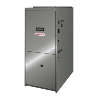
G51MP series units are high−efficiency multiple position
(upflow, downflow, horizontal left and horizontal right)
gas furnaces manufactured with Lennox DuralokPlust
aluminized and stainless steel clamshell-type heat ex-
changers. G51MP units are available in heating input ca-
pacities of 44,000 to 132,000 Btuh (13 to 38.6 kW) and cool-
ing applications from 2 through 5 tons (7.0 through 17.6 kW).
Refer to Engineering Handbook for proper sizing.
Units are factory equipped for use with natural gas. A kit is
available for conversion to LPG operation. All G51MP units
are equipped with the Lennox SureLight
tion system. The gas valve is redundant to assure safety
shut−off as required by C.S.A.
The heat exchanger, burners and manifold assembly can be
removed for inspection and service. The maintenance section
gives a detailed description on how this is done.
Information contained in this manual is intended for use by
qualified service technicians only. All specifications are sub-
ject to change. Procedures outlined in this manual are pre-
sented as a recommendation only and do not supersede or
replace local or state codes.
Table of Contents
General
. . . . . . . . . . . . . . . . . . . . . . . . . . . . . . . . . . . . . .
. . . . . . . . . . . . . . . . . . . . . . . . . . . . . . . . .
I−Unit Components
. . . . . . . . . . . . . . . . . . . . . . . . . . . .
II Placement and Installation
III−Start−Up
. . . . . . . . . . . . . . . . . . . . . . . . . . . . . . . . . . .
IV−Heating System Service Checks
V−Typical Operating Conditions
VI−Maintenance
. . . . . . . . . . . . . . . . . . . . . . . . . . . . . . .
VII−Wiring and Sequence of Operation
VIII−Troubleshooting
. . . . . . . . . . . . . . . . . . . . . . . . . . .
Revised 9−2007
G51MP SERIES UNITS
®
hot surface igni-
. . . . . . . . . . . . . . . . . . . . . .
. . . . . . . . . . . . . . . . . . . .
. . . . . . . . . . . . . .
. . . . . . . . . . . . . . . . .
. . . . . . . . . . .
Corp. 0307−L5
1
2
Improper installation, adjustment, alteration, service
4
or maintenance can cause property damage, person-
9
al injury or loss of life. Installation and service must
be performed by a qualified installer, service agency
19
or the gas supplier.
33
34
38
39
Electric shock hazard. Can cause injury
or death. Before attempting to perform
42
any service or maintenance, turn the
48
electrical power to unit OFF at discon-
nect switch(es). Unit may have multiple
power supplies.
Sharp edges.
Be careful when servicing unit to avoid sharp edges
which may result in personal injury.
Page 1
G51MP
IMPORTANT
WARNING
WARNING
© 2003 Lennox Industries Inc.
Litho U.S.A.
Advertisement
Table of Contents

Related Manuals for Lennox G51MP


Summary of Contents for Lennox G51MP
- Page 1 Lennox DuralokPlust aluminized and stainless steel clamshell-type heat ex- changers. G51MP units are available in heating input ca- pacities of 44,000 to 132,000 Btuh (13 to 38.6 kW) and cool- ing applications from 2 through 5 tons (7.0 through 17.6 kW).
-
Page 2: Specifications
132 (60) 136 (62) 146 (66) 164 (74) 168 (76) Electrical characteristics 120 volts − 60 hertz − 1 phase (less than 12 amps) SPECIFICATIONS Model No. G51MP−60C−090 G51MP−48C−110 G51MP−60C−110 G51MP−60D−135 Heating Input − Btuh (kW) 88,000 (25.8) 110,000 (32.2) 110,000 (32.2) - Page 3 OPTIONAL ACCESSORIES B" Width Models C" Width Models D" Width Models FILTER KITS Air Filter and Horizontal (end) Size of filter − in. 87L96 − 18 x 25 x 1 87L97 − 20 x 25 x 1 87L98 − 25 x 25 x 1 Rack Kit (457 x 635 x 25) (mm)
-
Page 4: Blower Performance
BLOWER PERFORMANCE G51MP−24B−045 PERFORMANCE (Less Filter) Air Volume / Watts at Different Blower Speeds External Static External Static Pressure High Medium in. w.g. Watts Watts Watts 0.00 1225 1000 0.10 1190 0.20 1160 0.30 1120 0.40 1070 0.50 1015 0.60 0.70... -
Page 5: G51Mp−36C/48C−090 Performance
BLOWER PERFORMANCE G51MP−36C−090 PERFORMANCE (Less Filter) Air Volume / Watts at Different Blower Speeds External Static External Static Pressure High Medium−High Medium−Low in. w.g. Watts Watts Watts Watts 0.00 1630 1360 1125 0.10 1620 1365 1160 1000 0.20 1590 1365 1160 0.30... - Page 6 BLOWER PERFORMANCE G51MP−60C−090 PERFORMANCE (Less Filter) − Single Side Return Air − Air volumes in bold require field fabricated transi- tion to accommodate 20 x 25 x 1 in. (508 x 635 x 25 mm) air filter in order to maintain proper air velocity.
- Page 7 BLOWER PERFORMANCE G51MP−60C−110 PERFORMANCE (Less Filter) − Bottom Return Air, Side Return Air with Optional RAB Return Air Base, Re- turn Air from Both Sides or Return Air from Bottom and One Side. External Static Air Volume / Watts at Different Blower Speeds...
-
Page 8: G51Mp Parts Identification
G51MP PARTS IDENTIFICATION TOP CAP DuralokPlus HEAT EXCHANGER ASSEMBLY CABINET BURNER BOX ASSEMBLY GAS VALVE AND MANIFOLD BURNER BOX COVER FLUE COLLAR WARM HEADER COMBUSTION (COLLECTOR) AIR PROVE SWITCHES COMBUSTION AIR CONDENSER COIL INDUCER BURNER PRIMARY LIMIT ACCESS PANEL COLD HEADER... - Page 9 B−Control Box Components (Figure 3) Unit transformer (T1), igntion control (A92) and circuit G51MP unit components are shown in figure 1. The com- breaker (CB8) are located in the control box. In addition, a bustion air inducer, gas valve and burners can be accessed door interlock switch (S51) is located in the control box.
- Page 10 TABLE 1 WARNING IGNITION CONTROL 97L48 J156 TERMINAL DESIGNATIONS Shock hazard. PIN # FUNCTION Disconnect power before servicing. Control is not field repairable. If control is inoperable, sim- Ignitor ply replace entire control. Not Used Can cause injury or death. Unsafe operation will result if repair is attempted.
- Page 11 TABLE 3 FAN-OFF TIME ADJUSTMENT 120sec. 60sec. 90sec. 180sec. IGNITION CONTROL 97L48 TERMINAL DESIGNATIONS ACB COOL blower − cooling speed (line voltage) ACB HEAT blower − heating speed (line voltage) PARK alternate blower speeds (Black square indicates switch position) ACB LOW continuous low speed To adjust fan−off timing, set dip switch to desired setting.
- Page 12 INTEGRATED IGNITION CONTROL 69M15 69M15 (A92) Figure 8 G51MP045−2, 070−2, 110−2, 135−2, 090−3 and later dash number units are also equipped with the Lennox SureLight hot surface ignition system. Like earlier dash number units, the system consists of ignition control board, ignitor and sensor.
- Page 13 a−Electronic Ignition (See Figure 7) b−Fan Time Control Heating On a call for heat the ignition control board monitors the The heating fan on time of 45 seconds is not adjustable. Fan combustion air inducer prove switch. The ignition control off time (time that the blower operates after the heat de- will not begin the heating cycle if the prove switch is closed mand has been satisfied) can be adjusted by setting the S1...
- Page 14 ® The SureLight integrated ignition control is equipped with two LED lights for troubleshooting. The diagnostic codes are listed below in table 8. TABLE 8 DIAGNOSTIC CODES Make sure to Identify LED’S Correctly. Refer to figure 6 or 8. LED #1 LED #2 97L48 −...
- Page 15 3. Primary Limit Control (S10) from lifting off the burner head. In addition, the burner entrance Figure 11 shows the primary limit (S10) used on G51MP units to each clamshell is fitted with a corbel cup (orifice) used to di- located in the heating vestibule panel.
- Page 16 PRESSURE BARBED SWITCH the gas valve. Switch S47 in all G51MP units is factory pre- FITTING (LP ONLY) MANIFOLD set to open at 250_F + 12_F (121_C + 6.7_C) on a tempera-...
- Page 17 9. Combustion Air Inducer (B6) PROVE SWITCH (S18) side view negative (−) barb All G51MP units use a combustion air inducer to move air gray through the burners and heat exchanger during heating operation. The blower uses a shaded pole 120VAC motor.
- Page 18 2. Secondary Limit Controls (S21) 1.00"(249) .95" (236) .85" (211) and later The secondary limits (S21) on G51MP units are located in the −070−1 to .95" (236) .95" (236) .85" (211) blower compartment in the back side of the blower housing.
- Page 19 II−PLACEMENT AND INSTALLATION Make sure unit is installed in accordance with installation in- structions and applicable codes. TABLE 11 OUTDOOR TERMINATION KITS AND CORRESPONDING EQUIVALENCIES Vent Pipe Length Equivalency (feet) Outdoor Outdoor 2" Wall Exhaust Exhaust 1−1/2" 2" Con- 3" Con- VENT 2"...
- Page 20 2.5 feet (.76m) of vent pipe of the same diameter. ***G51MP−60D−135 must have 3" to 2" reducing ell (supplied) installed directly In some applications which permit the use of several differ- into unit flue collar.
- Page 21 *G51MP−48C−110 and G51MP−60C−110 must have 90° street ell (supplied) installed directly into unit flue collar. installed directly into unit flue collar. **G51MP−60D−135 must have 3" to 2" reducing ell (supplied) installed directly **G51MP−60D−135 must have 3" to 2" reducing ell (supplied) installed directly into unit flue collar.
- Page 22 B−PVC Joint Cementing Procedure 6 − Promptly apply solvent cement to end of pipe and in- side socket surface of fitting. Cement should be ap- All cementing of joints should be done according to the plied lightly but uniformly to inside of socket. Take care specifications outlined in ASTM D 2855.
- Page 23 24" (610mm) maximum and 3/4" (19mm) minimum. If a G51MP furnace replaces a furnace which 4. Secure piping at the point where it exits the outside wall...
- Page 24 2"* 2”* 3"** G51MP−110 with G51MP−135 with *2" diameter street elbow provided. G51MP−110−1, −2 units with 2” vent pipe 3" OR 4" vent pipe **3" diameter reducing elbow provided. 2−1/2", 3", OR 4" vent pipe ***Limit pipe length to 2".
- Page 25 The G51MP furnace may be installed in either direct vent 1 − Cement intake piping in slip connector located on the or non−direct vent applications. In non−direct vent applica- side of the burner box. tions, when intake air will be drawn into the furnace from the 2 −...
- Page 26 TYPICAL AIR INTAKE PIPE CONNECTIONS Direct Vent applications where combustion air is taken HORIZONTAL DIRECT VENT APPLICATIONS (Horizontal Right−Hand Air Discharge Application Shown) from indoors and flue gases are discharged outdoors. G51MP−24B−045 G51MP−36B−045 2−1/2”, G51MP−36B−070 *Limit pipe 3” OR 4”...
- Page 27 The G51MP is then classified as a non-direct vent, placed into operation could result in carbon monox- Category IV gas furnace. In Non-Direct Vent applications, ide poisoning or death.
- Page 28 In accordance to CSA International B149 installation vent freeze−ups. Heating cable installation kit is available codes, the minimum allowed distance between the from Lennox. See Condensate Piping section for part num- combustion air intake inlet and the exhaust outlet of bers.
- Page 29 18. Refer to figure 31 for proper piping EXHAUST PIPE TERMINATION SIZE REDUCTION method. In addition, WTK wall termination kit must be G51MP Exhaust Pipe Size Termination Pipe Size extended for use in this application. See figure 34.
-
Page 30: Front View
EXHAUST VENT EXHAUST 12" (305) ABOVE TERMINATION AVERAGE SNOW ACCUMULATION Front View INTAKE Inches (mm) VENT INTAKE TERMINATION 1/2" (13) Foam Insulation Side View in Unconditioned Space FIELD− FIELD−PROVIDED PROVIDED EXHAUST VENT REDUCER MAY BE REQUIRED REDUCER MAY TO ADAPT LARGER VENT BE REQUIRED PIPE SIZE TO TERMINATION TO ADAPT... - Page 31 WALL TERMINATION KIT (22G44, 44J40, 30G28 or 81J20) EXTENDED VENT FOR GRADE CLEARANCE FIGURE 34 haust piping should extend a maximum of 12 inches G51MP DIRECT VENT APPLICATION (305mm) beyond the outside wall, unless support is STRAIGHT−CUT OR USING EXISTING CHIMNEY ANGLE−CUT IN DIRECTION...
- Page 32 FIGURE 38 appropriate location on the side of the unit. NOTE − The condensate trap is factory−shipped with G51MP NON−DIRECT VENT APPLICATION two rubber O−rings and two rubber clean−out caps USING EXISTING CHIMNEY installed. Check to make sure that these items are in place before installing the trap assembly.
- Page 33 6 ft. (1.8m) − kit no. 26K68; 24 ft. (7.3m) − kit no. The gas valve on the G51MP may be equipped with either 26K69; and 50 ft. (15.2m) − kit no. 26K70.
- Page 34 MANIFOLD labeled by the installer. PRESSURE OUTLET POST A−C.S.A. Certification All units are C.S.A. design certified without modifications. MANIFOLD PRESSURE Refer to the G51MP Operation and Installation Instruction ADJUSTMENT Manual Information. INLET SCREW PRESSURE B−Gas Piping POST GAS VALVE SHOWN IN OFF POSITION Gas supply piping should not allow more than 0.5"W.C.
- Page 35 Use of a specialty IMPORTANT Gas Leak Detector is strongly recommended. It is available through Lennox under part number 31B2001. See Corp. The White Rodgers 36G gas valve (figure 42) is 8411−L10, for further details.
- Page 36 Manifold operating pressure for the G51MP can be measured G− Proper Combustion at any time the gas valve is open and is supplying gas to the Furnace should operate at least 15 minutes with correct unit. manifold pressure and gas flow rate before checking com- bustions.
- Page 37 The combustion air pressure switches are factory−set and NOTE−MUST USE DIGITAL METER require no adjustment. NOTE − Pressure switch is factory set. No adjustment necessary. All mod- els use the factory installed pressure switch from 0−4500 feet (0−1370 m). SET DIAL TO MEASURE VDC TABLE 21 Manifold Pressure (Outlet) inches w.c.
- Page 38 B−Temperature Rise 4 − Static pressure must not exceed 0.5" W.C. 5 − Seal around the hole when the check is complete. Temperature rise for G51MP units depends on unit input, D−Blower Speed Taps blower speed, blower horsepower, filter resistance and (G51MP−2 &...
- Page 39 G51MP BLOWER REMOVAL To Remove Blower: Turn off line voltage power. 1 Disconnect thermostat wiring con- nections. 2 Disconnect blower leads from control board and secondary limit wires. 3 Disconnect secondary limit wire plug. 4. Loosen screws (2) and remove con- trol box from unit.
- Page 40 Cleaning Heat Exchanger 18 − Remove two screws from the front cabinet flange at the blower deck. Spread cabinet sides slightly to allow clearance for removal of heat exchanger. IMPORTANT 19 − Remove screws along vestibule sides and bottom which secure vestibule panel and heat exchanger as- Safety glasses and surgical mask should be worn sembly to cabinet.
- Page 41 42 − Replace the blower compartment access panel. 6 − Use the soft brush attachment on a vacuum cleaner to gently clean the face of the burners. Visually inspect 43 − Refer to instruction on verifying gas and electrical con- the inside of the burners and crossovers for any block- nections when re−establishing supplies.
- Page 42 VII−WIRING DIAGRAM AND SEQUENCE OF OPERATION 1 − When there is a call for heat, W1 of the thermostat en- 5 − Gas valve opens for a 4−second trial for ignition ergizes W of the furnace control with 24VAC. 6 − Flame is sensed, gas valve remains open for the heat 2 −...
- Page 43 1 − When there is a call for heat, W1 of the thermostat en- 5 − Gas valve opens for a 4−second trial for ignition ergizes W of the furnace control with 24VAC. 6 − Flame is sensed, gas valve remains open for the heat 2 −...
- Page 44 SURELIGHT CONTROL HEATING SEQUENCE OF OPERATION Control board 69M15 RED LED #1 = DS1 & GREEN LED #2 = DS2 Control board 97L48 GREEN LED #1 = DIAG1 & GREEN LED #2 = DIAG2 NORMAL HEATING MODE ABNORMAL HEATING MODE POWER ON GAS VALVE OFF.
- Page 45 NORMAL HEATING MODE ABNORMAL HEATING MODE 15-SECOND COMBUSTION AIR INDUCER PREPURGE INITIATED BY CLOSED PRESSURE SWITCH. IS VOLTAGE ABOVE 75 VOLTS? LEDS SIGNAL IGNITOR WARM-UP −− 20 SECONDS. ALTERNATING IS THERE A PROPER GROUND? FAST FLASH IS IGNITOR INTACT AND CONNECTED? 4-SECOND TRIAL FOR IGNITION.
- Page 46 SURELIGHT CONTROL COOLING SEQUENCE OF OPERATION NORMAL COOLING MODE ABNORMAL COOLING MODE POWER ON IGNITION CONTROL MAIN POWER ON. GAS VALVE OFF. COMBUSTION AIR INDUCER OFF. INDOOR BLOWER OFF WITH NORMAL DELAY. CONTROL SELF DIAGNOSTIC CHECK. SIGNAL CIRCUIT BOARD FAILURE AT LED. IS CONTROL OPERATING NORMALLY? INTERRUPT MAIN POWER TO RESET CONTROL.
- Page 47 SURELIGHT CONTROL CONTINUOUS FAN SEQUENCE OF OPERATION LED: SLOW FLASH RATE REMAINS UNCHANGED THROUGHOUT SEQUENCE. MANUAL FAN SELECTION MADE AT THERMOSTAT. CONTROL (G) ENERGIZES INDOOR BLOWER ON CONTINUOUS BLOWER SPEED. ELECTRONIC AIR CLEANER TERMINAL IS ENERGIZED. HEATING ACCESSORY TERMINAL THERMOSTAT CALLS FOR HEAT (W). ENERGIZES WITH COMB.
- Page 48 VIII−INTEGRATED IGNITION CONTROL TROUBLESHOOTING CHART UPON INITIAL POWER UP, REMOVE ALL THERMOSTAT DEMANDS TO THE UNIT PROBLEM: 1 UNIT FAILS TO OPERATE IN THE COOLING, HEATING, OR CONTINUOUS FAN MODE Condition Possible Cause Corrective Action / Comments 1.1.1 ACTION 1 − Check 120V main voltage. −...
- Page 49 PROBLEM 1: UNIT FAILS TO OPERATE IN THE COOLING, HEATING, OR CONTINUOUS FAN MODE Condition Possible Cause Corrective Action / Comments ACTION 1 − Check that the unit is properly 1.5.1 ground. − Diagnostic lights flash the improper ACTION 2 − Install a proper main ground to the Improper ground to the unit.
- Page 50 PROBLEM 2: UNIT FAILS TO FIRE IN THE HEATING MODE, COMBUSTION AIR INDUCER DOES NOT ENERGIZE (CONT.). Condition Possible Cause Corrective Action/Comments − Unit operates with a cooling and con- 2.3.1 ACTION 1 − Check for correct wiring and loose tinuous fan demand.
- Page 51 PROBLEM 4: UNIT FAILS TO FIRE IN THE HEATING MODE, COMBUSTION AIR BLOWER ENERGIZES, IGNITOR IS ENERGIZED. Condition Possible Cause Corrective Action/Comments ACTION 1 − Check line pressure at the gas valve. 4.1.1 Pressure should not exceed 13" WC for both nat- −...
- Page 52 ACTION 2 − Seal leakage if possible, replace heat secondary heat exchanger, and exchanger if necessary, tag and return heat ex- changer to proper Lennox personnel. combustion air blower. 5.3.4 ACTION 1 − Check for sooting deposits or other Insufficient flow through the heat restrictions in the heat exchanger assembly.
- Page 53 PROBLEM 6: CONTROL SIGNALS LOW FLAME SENSE DURING HEATING MODE Condition Possible Cause Corrective Action/Comments 6.1.1 ACTION 1 − Check the sensor rod for proper loca- − Unit operates correctly but the diag- tion on the burner. Properly locate the sensor rod Sensor rod is improperly located on or replace if rod cannot be located correctly.