Table of Contents
Advertisement
AV Receiver
TX-SR603/603E
TX-SR8360
Instruction Manual
Thank you for purchasing an Onkyo AV Receiver.
Please read this manual thoroughly before making
any connections and plugging it in.
Following the instructions in this manual will enable
you to obtain optimum performance and listening
enjoyment from your new AV Receiver.
Please retain this manual for future reference.
Contents
Introduction ............................... 2
Connections ............................ 21
First Setup ............................... 39
Basic Operations .................... 53
Advanced Operations ............. 64
Advanced Setup ...................... 68
Zone 2 ...................................... 74
Using the Remote Controller
with Other Components ...... 78
Specifications.......................... 88
Troubleshooting ...................... 89
E
n
Advertisement
Table of Contents

Related Manuals for Onkyo TX-SR603/603E


Summary of Contents for Onkyo TX-SR603/603E
- Page 1 AV Receiver TX-SR603/603E TX-SR8360 Instruction Manual Thank you for purchasing an Onkyo AV Receiver. Please read this manual thoroughly before making any connections and plugging it in. Following the instructions in this manual will enable you to obtain optimum performance and listening enjoyment from your new AV Receiver.
-
Page 2: Important Safety Instructions
WARNING: TO REDUCE THE RISK OF FIRE OR ELECTRIC SHOCK, DO NOT EXPOSE THIS APPARATUS TO RAIN OR MOISTURE. CAUTION: TO REDUCE THE RISK OF ELECTRIC SHOCK, DO NOT REMOVE COVER (OR BACK). NO USER-SERVICEABLE PARTS INSIDE. REFER SERVICING QUALIFIED PERSONNEL. -
Page 3: For Canadian Model
2. AC Fuse — The AC fuse inside the AV receiver is not user-serviceable. If you cannot turn on the AV receiver, contact your Onkyo dealer. 3. Care —Occasionally you should dust the AV receiver all over with a soft cloth. For stubborn stains, use a soft cloth dampened with a weak solu- tion of mild detergent and water. -
Page 4: Supplied Accessories
We, ONKYO EUROPE ELECTRONICS GmbH LIEGNITZERSTRASSE 6, 82194 GROEBENZELL, GERMANY declare in own responsibility, that the ONKYO product described in this instruction manual is in compliance with the corresponding technical standards such as EN60065, EN55013, EN55020 and EN61000-3-2, -3-3. GROEBENZELL, GERMANY... - Page 5 Dolby Laboratories. *2. “DTS,” “DTS 96/24,” “DTS-ES,” and “Neo:6” are trademarks of Digital Theater Systems, Inc. *3. “CinemaFILTER” is a trademark of Onkyo Corporation. “Xantech” is a registered trademark of Xantech Corporation. “Niles” is a registered trademark of Niles Audio Corporation.
-
Page 6: Introduction
Table of Contents Introduction Important Safety Instructions ...2 Precautions ...3 Supplied Accessories...4 Features ...5 Table of Contents ...6 Front & Rear Panels...8 Remote Controller...13 About Home Theater ...20 Connecting the AV Receiver About AV Connections ...21 Connecting Your Speakers...22 Connecting Antenna...24 Connecting Your TV or Projector ...27 Connecting AV Components ...28 Connecting Audio Components ...34... -
Page 7: Table Of Contents
Table of Contents —Continued Controlling Other Components Entering Remote Control Codes... 78 Advanced Learning Commands from Another Remote Controller ... 86 Features Using Macros... 87 Advanced Setup Adjusting the Bass & Treble ... 68 Audio Adjust Functions... 68 Assigning Listening Modes to Input Sources ... 70 Advanced IntelliVolume ... -
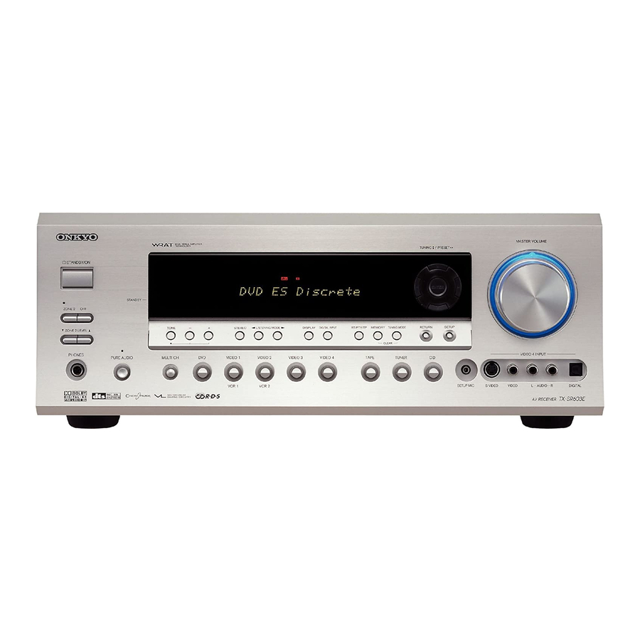
Page 8: Front Panel
Front & Rear Panels Front Panel TX-SR603/603E, TX-SR8360 STANDBY/ON STANDBY ZONE2 TONE ZONE 2 LEVEL PHONES PURE AUDIO MULTl CH The page numbers in parentheses show where you can find the main explanation for each item. STANDBY/ON button (38) This button is used to set the AV receiver to On or Standby. - Page 9 Front & Rear Panels —Continued SETUP button This button is used to access the onscreen setup menus that appear on the connected TV. MASTER VOLUME control (53) This control is used to adjust the volume of the AV receiver to MIN, 1 through 99, or MAX. PHONES jack (54) This 1/4-inch phone jack is for connecting a stan- dard pair of stereo headphones for private listening.
- Page 10 Front & Rear Panels —Continued Display The page numbers in parentheses show where you can find the main explanation for each item. MUTING indicator (54) This indicator flashes while the AV receiver is muted. ZONE 2 indicator (76) This indicator lights up when Zone 2 is selected. Listening mode &...
-
Page 11: Rear Panel
Front & Rear Panels —Continued Rear Panel TX-SR603/603E, TX-SR8360 1B CD IR IN 12 V TRIGGER OUT AV RECEIVER ZONE 2 TX-SR 603E MODEL NO. DIGITAL COAXIAL IN 1 ANTENNA FM 75 COMPONENT VIDEO IN 3 IN 2 IN 1... - Page 12 REMOTE CONTROL This (Remote Interactive) jack can be con- nected to an jack on another Onkyo AV compo- nent. The AV receiver’s remote controller can then be used to control that component. To use must make an analog audio connection (RCA) between the AV receiver and the other AV compo- nent, even if they are connected digitally.
-
Page 13: Remote Controller
Remote Controller Installing the Batteries To open the battery compartment, press the small hollow and slide off the cover. Insert the three supplied batteries (AA/R6) in accordance with the polarity diagram inside the battery compartment. Put the cover onto the remote controller and slide it shut. - Page 14 Remote Controller —Continued In addition to controlling the AV receiver, the remote controller has several operating modes for controlling your other AV components, including Onkyo compo- nents connected via . Modes are selected by using the remote controller’s REMOTE MODE buttons.
- Page 15 This button is used to select the Direct listening mode. DSP] & [DSP ] buttons These buttons are used to select the Onkyo original DSP (digital signal processor) listening modes and Mono listening mode. TEST TONE, CH SEL, LEVEL-, & LEVEL+...
-
Page 16: Dvd Mode
Numbers in circles are for DVD mode. Numbers in squares are for CD mode. DVD Mode DVD mode is used to control an Onkyo DVD player connected to the AV receiver via To set the remote controller to DVD mode, press the [DVD] REMOTE MODE button. - Page 17 CD Mode CD mode is used to control an Onkyo CD player con- nected to the AV receiver via To set the remote controller to CD mode, press the [CD] REMOTE MODE button.
- Page 18 Numbers in circles are for MD/CDR mode. Numbers in squares are for TAPE mode. MD/CDR Mode MD/CDR mode is used to control an Onkyo MiniDisc recorder or CD recorder connected to the AV receiver via To select MD/CDR mode, press the [MD/CDR] REMOTE MODE button.
-
Page 19: Tape Mode
TAPE Mode TAPE mode is used to control an Onkyo cassette recorder connected to the AV receiver via To set the remote controller to TAPE mode, press the [TAPE] REMOTE MODE button. -
Page 20: About Home Theater
With DVDs you can enjoy DTS and Dolby Digital. With analog and digital TV you can enjoy Dolby Pro Logic IIx or Onkyo’s own DSP surround listening modes. Front left and right speakers These output the overall sound. -
Page 21: Connections
Connecting the AV Receiver About AV Connections • Before making any AV connections, read the manuals supplied with your other AV components. • Don’t connect the power cord until you’ve completed and double-checked all AV connections. Optical Digital Jacks The AV receiver’s optical digital jacks have shutter-type covers that open when an optical plug is inserted and close when it’s removed. -
Page 22: Connecting Your Speakers
Connecting the AV Receiver —Continued Connecting Your Speakers Speaker Configuration For the best surround sound experience, you should con- nect seven speakers and a powered subwoofer. The following table indicates the channels you should use depending on the number of speakers that you have. Number of speakers: Front left Front right... -
Page 23: Connecting The Av Receiver —Continued
Doing so may damage the AV receiver. • Make sure the metal core of the wire does not have contact with the TX-SR603/603E/8360’s rear panel. Doing so may dam- age the AV receiver. • Don’t connect more than one cable to each speaker terminal. -
Page 24: Connecting Antenna
Connecting the AV Receiver —Continued Connecting Antenna This section explains how to connect the supplied indoor FM antenna and AM loop antenna, and how to connect commercially available outdoor FM and AM antennas. The AV receiver won’t pick up any radio signals without any antenna connected, so you must connect the antenna to use the tuner. - Page 25 Connecting the AV Receiver —Continued Connecting an Outdoor FM Antenna If you cannot achieve good reception with the supplied indoor FM antenna, try a commercially available out- door FM antenna instead. Notes: • Outdoor FM antennas work best outside, but usable results can sometimes be obtained when installed in an attic or loft.
-
Page 26: Which Connections Should I Use
MONITOR OUT jacks, not the VIDEO 1 and VIDEO 2 OUT V and S jacks. Note: The TX-SR603/603E/8360 can be set to upcon- vert composite video and S-Video input signals and output them from the COMPONENT VIDEO OUT (see page 44). -
Page 27: Connecting Your Tv Or Projector
Connecting the AV Receiver —Continued Connecting Your TV or Projector Monitor Out I Using Composite Video Use a composite video cable to connect the AV receiver’s V MONITOR OUT jack to a composite video input on your TV, as shown. TV, projector, etc. -
Page 28: Connecting A Dvd Player
Connecting the AV Receiver —Continued Connecting a DVD Player Video Connections You only need to use one of the following connection methods. I Using Composite Video Use a composite video cable to connect the AV receiver’s V DVD IN jack to the composite video output on your DVD player, as shown. - Page 29 Connecting the AV Receiver —Continued I Using a Multichannel Connection If your DVD player supports multichannel audio formats such as DVD-Audio, and it has a 5.1-channel analog audio output, you can enjoy DVD-Audio playback. Use a multichannel analog audio cable to connect the AV receiver’s DVD IN FRONT L/R, CENTER, SUR- ROUND L/R, and SUBWOOFER jacks to the 5.1- channel analog audio output on your DVD player, as...
- Page 30 Connecting an HDD/DVD recorder for Playback Video Connections With the initial settings of the TX-SR603/603E/8360, the VIDEO 1 input source is set for the COMPONENT VIDEO IN 2 jacks. If you connect the device to the COMPONENT VIDEO IN 3 jacks, see page 44.
- Page 31 Connecting the AV Receiver —Continued Connecting a VCR for Recording This section explains how to connect a VCR for recording from a TV or another VCR. Video Connections • Use an S-Video cable to connect the AV receiver’s S VIDEO 1 OUT jack to an S-Video input on the recording VCR.
- Page 32 Connecting the AV Receiver —Continued Connecting Other Video Sources— Satellite, Cable, Set-top box, LD Player, etc. Video Connections You only need to use one of the following connection methods. I Using Composite Video Use a composite video cable to connect the AV receiver’s V VIDEO 3 IN jack to a composite video output on your video source, as shown.
- Page 33 Connecting the AV Receiver —Continued I Using Analog Connections If your video source doesn’t have a digital audio output, or you want to record from it, you’ll need to make the following analog audio connection. Use an analog audio cable to connect the AV receiver’s VIDEO 3 IN L/R jacks to the analog audio output on your video source, as shown.
-
Page 34: Connecting A Cd Player
Connecting the AV Receiver —Continued Connecting a CD Player I Using Optical or Coaxial Connections If you connect to a digital audio input, you’ll need to assign it (see page 43). • Use an optical digital audio cable to connect one of the AV receiver’s OPTICAL DIGITAL IN jacks to the optical output on your CD player, as shown. - Page 35 Connecting the AV Receiver —Continued I Using Optical or Coaxial Connections (playback only) If you connect to a digital audio input, you’ll need to assign it (see page 43). • Use an optical digital audio cable to connect one of the AV receiver’s OPTICAL DIGITAL IN jacks to the optical output on your recorder, as shown.
-
Page 36: Connecting A Turntable
Connecting the AV Receiver —Continued Connecting a Turntable I Turntable with a Built-in Phono Preamp Use an analog audio cable to connect an unused audio input on the AV receiver to the audio outputs on your turntable, as shown. AUDIO OUTPUT I Turntable without a Built-in Phono Preamp Use an analog audio cable to connect an unused audio... -
Page 37: Connecting Components
Connecting Components With (Remote Interactive) you can control your -compatible Onkyo CD player, DVD player, and so on with the AV receiver’s remote controller, as follows: • To use , you must make an analog audio con- nection between the AV receiver and the other AV components, even if they are connected digitally. -
Page 38: Turning On The Av Receiver
Connecting the AV Receiver —Continued Turning On the AV Receiver • Before connecting the power cord, connect all your speakers and AV components. • Turning on the AV receiver may cause a momentary power surge that might interfere with other electrical equipment on the same circuit. -
Page 39: First Time Setup
First Time Setup This chapter explains the settings that you need to make before using the AV receiver. Automatic Speaker Setup With the supplied speaker setup microphone, the Auto- matic Speaker Setup function can measure the test tone output by each speaker and automatically determine the number of speakers connected, their sizes, the distance from each speaker to the listening position, and so on. - Page 40 First Time Setup —Continued Press [ENTER]. ENTER The automatic speaker setup starts. The test tone is output by each speaker in turn, measured by the microphone, and the speaker settings set accordingly. The whole process takes about 2 minutes. If any extraneous noise is picked up by the microphone, the automatic setup may not work correctly, so be careful.
- Page 41 First Time Setup —Continued (Menus vary depending on country) When a speaker has a warning, its abbrevia- tion (e.g., L, R, and so on) appears. Not Detect: No speaker was detected. Make sure the connection is secured correctly. Distance Error: The positions of the speakers are too close or too far, or the distance could not be measured.
-
Page 42: About The Onscreen Setup Menus
First Time Setup —Continued About the Onscreen Setup Menus The AV receiver is configured using onscreen setup menus, which are displayed on the TV that’s connected to either of the MONITOR OUT jacks. Because they appear on your TV, they’re large and clear, making setup a breeze. Main menu * For multichannel connection, “3. -
Page 43: Initial Setup
First Time Setup —Continued Initial Setup Digital Input If you connect a component to a digital input jack, you must assign that jack to an input selector. For example, if you connect your CD player to the OPTICAL IN2 jack, you should assign that jack to the CD input selec- tor. -
Page 44: Component Video Setup
First Time Setup —Continued Component Video Setup If you connect to a COMPONENT VIDEO IN, you must assign it to an input selector. For example, if you connect your DVD player to COMPONENT IN 3, you should assign it to the DVD input selector. If you want to output composite and S-Video sources from the COMPONENT VIDEO OUT, select VIDEO, as explained below. -
Page 45: Tv Format Setup (Not North American Models)
First Time Setup —Continued Press the [RECEIVER] button fol- RECEIVER lowed by the [SETUP] button. The main menu appears onscreen. Use the Up and Down [ buttons to select “0. Initial Setup,” and then press [ENTER]. ENTER The Initial Setup menu appears. ENTER (Menus vary depending on country.) Use the Up and Down [... -
Page 46: Speaker Setup
First Time Setup —Continued AM Frequency Step Setup (some models only) Here you can specify the AM frequency step used in your area. When this setting is changed, all radio presets are deleted. Press the [RECEIVER] button fol- lowed by the [SETUP] button. RECEIVER The main menu appears onscreen. - Page 47 First Time Setup —Continued Use the Up and Down [ buttons to select “1. Speaker Config,” and then press [ENTER]. ENTER The Speaker Config menu appears. ENTER Use the Up and Down [ buttons to select “a. Subwoofer,” and then use the Left and Right ENTER ] buttons to select: Yes: Select if a subwoofer is con-...
- Page 48 First Time Setup —Continued Crossover Use the Up and Down [ buttons to select “g. Crossover,” and then use the Left and Right ENTER ] buttons to select a crossover frequency. Choose a crossover frequency suitable for your setup. If you’re using a sub- woofer, choose a crossover frequency based on the diameter of your front speakers.
- Page 49 First Time Setup —Continued Speaker Distance This setting is set automatically by the Automatic Speaker Setup function (see page 39). Here you can specify the distance from each speaker to the listening position so that the sound from each speaker arrives at the listener’s ears as the sound designer intended.
- Page 50 First Time Setup —Continued Speaker Level Calibration This setting is set automatically by the Automatic Speaker Setup function (see page 39). Here you can adjust the level of each speaker with the built-in test tone so that the volume of each speaker is the same at the listening position.
- Page 51 First Time Setup —Continued Equalizer Setting This setting is set automatically by the Automatic Speaker Setup function (see page 39). Here you can adjust the EQ of individual speakers. To set the volume of individual speakers see page 50. Press the [RECEIVER] button fol- lowed by the [SETUP] button.
-
Page 52: Changing The Tape/Md/Cdr Display
First Time Setup —Continued Changing the TAPE/MD/CDR Display If you connect an -compatible Onkyo MiniDisc recorder or CD recorder to the TAPE IN/OUT jacks, for to work properly, you must change this setting. This setting can only be changed on the AV receiver. -
Page 53: Basic Operations
Basic Operations Selecting the Input Source This section explains how to select the input source (i.e., the AV component that you want to listen to or watch). Use the AV receiver’s input selector buttons to select the input Remote controller source. -
Page 54: Setting The Display Brightness
Basic Operations —Continued Press [RECEIVER] first DIMMER Setting the Display Brightness You can adjust the brightness of the display. Press the [RECEIVER] button, RECEIVER and then press the [DIMMER] button repeatedly to select: • Normal+VOLUME light on. • Normal+VOLUME light off. DIMMER •... -
Page 55: Displaying Source Information
Basic Operations —Continued Displaying Source Information You can display various information about the current input source as follows. RECEIVER DISPLAY Press the [RECEIVER] button, RECEIVER and then press the [DISPLAY] button repeatedly to cycle through the available informa- tion. DISPLAY Note: This procedure can also be performed on the AV receiver by using its [DISPLAY] button. -
Page 56: Using The Tuner
Basic Operations —Continued Using the Tuner With the built-in tuner you can enjoy AM and FM radio stations. You can store your favorite stations as presets for quick selection. Listening to the Radio Use the [TUNER] input selector TUNER button to select either AM or FM. In this example, FM has been selected. - Page 57 Basic Operations —Continued Presetting Radio Stations 2, 4 You can store up to 40 of your favorite radio stations as presets. Tune into the station that you want to store as a preset. Press the [MEMORY] button. The MEMORY indicator appears and MEMORY the preset number flashes.
- Page 58 Basic Operations —Continued Using RDS (European models only) RDS only works with European models and only in areas where RDS broadcasts are available. I What is RDS? RDS stands for Radio Data System and it’s a method of transmitting data in FM radio signals. It was developed by the European Broadcasting Union (EBU) and is avail- able in most European countries.
- Page 59 Basic Operations —Continued Displaying Radio Text (RT) When tuned to an RDS station that’s broadcasting RT text information, that information can be displayed. Press the [RT/PTY/TP] button RT/PTY/TP once. The RT information scrolls across the display. Notes: • The message “Waiting” may appear while the AV receiver waits for RT information.
-
Page 60: Selecting Listening Modes
While this mode is selected, the AV receiver outputs no video signals and its display is turned off. I [DIRECT] button This button selects the Direct listening mode. DSP] & [DSP These buttons select the Onkyo original DSP modes and Mono mode. ➔ Surround ALL ST... - Page 61 Basic Operations —Continued The following table lists all the listening modes and shows which modes can be selected for each input signal format. Analog, Input signal format PCM*1 Source CD, TV, LD, VHS, MD, turntable, radio, Listening mode cassette, DTV, etc. ❍...
-
Page 62: About The Listening Modes
Basic Operations —Continued About the Listening Modes With its built-in surround sound decoders and DSP pro- grams, the AV receiver can transform your home listen- ing room into a movie theater or concert hall. If you connect two surround back speakers (i.e., left and right), both will be used for 6.1-channel surround play- back. - Page 63 field that cannot be produced with conven- tional stereo. Use this mode with stereo material such as music CDs. Onkyo Original DSP Modes Orchestra Suitable for classical or operatic music. The surround channels are emphasized in order to widen the stereo image.
-
Page 64: Advanced Operations Using The Late Night Function (Dolby Digital Only)
Advanced Operations RECEIVER L NIGHT Using the Late Night Function (Dolby Digital only) With the Late Night function, you can reduce the dynamic range of Dolby Digital material so that you can still hear quiet parts even when listening at low volume levels—ideal for watching movies late at night when you don’t want to disturb anyone. -
Page 65: Adjusting Individual Speaker Levels
Advanced Operations —Continued MULTI CH RECEIVER CH SEL Adjusting Individual Speaker Levels You can adjust the level of individual speakers during playback. These adjustments are temporary and will be cancelled when the AV receiver is set to Standby. Press the [RECEIVER] button, RECEIVER use the [CH SEL] button to select each speaker, and use the... -
Page 66: Recording
Advanced Operations —Continued Adjusting Individual Speaker Levels You can adjust the level of individual speakers while using the DVD analog multichannel input. Adjusting with onscreen setup menus: Press the [RECEIVER] button fol- RECEIVER lowed by the [SETUP] button. The main menu appears onscreen. Use the Up and Down [ buttons to select “3. - Page 67 Advanced Operations —Continued AV Recording You can record AV input sources to an AV recording component (VCR, etc.) connected to the VIDEO 1 OUT, VIDEO 2 OUT, or TAPE OUT. See pages 27–37 for information on connecting components. Use the input selector buttons to select the AV component that VIDEO 1 VIDEO 2...
-
Page 68: Advanced Setup
Advanced Setup Adjusting the Bass & Treble You can adjust the bass and treble for the front speakers, except when the Direct or Pure Audio (not North Amer- ican TX-SR603) listening mode is selected. Press the [TONE] button repeat- edly to select either Bass or TONE Treble. - Page 69 Advanced Setup —Continued The Audio Adjust functions are explained below. Input Channel Settings I Multiplex This setting determines which channel is output from a stereo multiplex source. Use it to select audio channels or languages with multiplex sources, multilingual TV broadcasts, and so on.
-
Page 70: Assigning Listening Modes To Input Sources
Advanced Setup —Continued Assigning Listening Modes to Input Sources You can assign a default listening mode to each input source that will be selected automatically when you select each input source. For example, you can set the default listening mode to be used with Dolby Digital input signals. -
Page 71: Intellivolume
Advanced Setup —Continued IntelliVolume You can set the input level for each input source. This is useful if some of your AV components are louder or qui- eter than others. While this menu is shown onscreen, you can select each input source and set the levels while listening to and comparing them. -
Page 72: Digital Input Signal Formats
ID. You may need to change this if the remote controller’s control codes overlap with those of another Onkyo component located in the same room. • If you change the AV receiver’s remote control ID, be sure to set the same ID on both the AV receiver and remote controller (see page 73). -
Page 73: Changing The Remote Controller's Id
Advanced Setup —Continued Changing the Remote Controller’s ID If several Onkyo components are used in the same room, the remote controller’s control codes may overlap with those of another component. To differentiate the remote controller’s control codes, you can change its ID to another number. -
Page 74: Zone 2
Zone 2 Connecting Zone 2 With the Zone 2 function, you can enjoy one input source in the main room and a different source in another room. There are two connection methods: using a receiver/inte- grated amp in Zone 2 or using only a pair of speakers in Zone 2. -
Page 75: Setting The Powered Zone 2
Zone 2 —Continued Setting the Powered Zone 2 To use Zone 2, you must make this setting. It enables the speakers connected to the ZONE 2 SPEAKERS termi- nals so that they produce sound when Zone 2 is used. Press the [RECEIVER] button fol- RECEIVER lowed by the [SETUP] button. -
Page 76: Using Zone 2
Zone 2 —Continued Using Zone 2 Here you can turn on Zone 2, select an input source, and adjust the volume. Note: To control Zone 2 with the remote controller, you must press the [ZONE 2] button first. Point the remote controller at the ZONE AV receiver and press the [ZONE 2] button followed by the... -
Page 77: Using The Remote Control In Zone 2
Zone 2 —Continued Using the 12V Trigger When Zone 2 is turned on, the ZONE 2 12V TRIGGER OUT outputs 12 volts (100 milliamperes max). By con- necting this jack to the 12-volt trigger input on, say, a power amp in Zone 2, that power amp will turn on and off automatically as and when Zone 2 is turned on and off on the AV receiver. -
Page 78: Controlling Other Components Entering Remote Control Codes
If the remote controller works OK, the code has been entered correctly. If not, try again or try another code. Codes for Onkyo DVD Players The remote control code for an Onkyo DVD player depends on whether it’s connected via , as follows: 5001: Use this code if you’ve connected an... - Page 79 By default, some REMOTE MODE buttons are prepro- grammed with remote control codes for controlling Onkyo components connected via While holding down the REMOTE MODE button that you want to reset, press the TV [ Release both buttons and wait two sec- onds.
- Page 80 5009 Integra 5001, 5002 Integra Research 5001, 5002 5023 Kenwood 5017 Magnavox 5004, 5021 Marantz 5025, 5026 Mitsubishi 5005 Onkyo 5001, 5002 Panasonic 5011, 5017, 5020 Philips 5004, 5021, 5028 Pioneer 5006 Proscan 5003 5003 Sanyo 5012 5007, 5013, 5018,...
- Page 81 Controlling Other Components —Continued SAT (satellite receiver) Manufacturer Control code Manufacturer Tristar Aiwa 4016 Akai Unisat 4013 Universum 4021, 4024 Alba Vortec 4017 Anitech Wela 4025 Zehnder 4020 Baird Zenith 4032 Bell & Howell Blaupunkt CBL (cable receiver) Bush Manufacturer Control code 3001, 3002, 3021 Canon...
- Page 82 Controlling Other Components —Continued Manufacturer Control code 2001, 2002, 2003, 2008, 2010, 2013, 2021, 2023, 2025, 2026, 2027 2007, 2008, 2010, 2011, Realistic 2012, 2017 2048 Roadstar 2033, 2043 Runco 2019 Saba 2040, 2048 Saisho 2028, 2041 Salora 2030 Samsung 2008, 2043, 2049 Sansui 2006, 2032...
- Page 83 Controlling Other Components —Continued Manufacturer Control code Manufacturer Loewe 1014, 1040, 1055 Quasar Luxman 1004, 1006 Quelle 1001, 1006, 1010, 1014, 1016, 1017, 1034 Radio Shack M Electronic 1035, 1053, 1062, 1063 Radio Shack/ Magnadyne 1040, 1067, 1068 Realistic Magnafon 1067 Radiola 1004, 1006, 1008, 1014,...
- Page 84 Controlling Other Components —Continued To control another component, point the remote control- ler at it and use the buttons as explained below (you must select the appropriate remote control mode first). Controlling a TV STANDBY Number buttons Press [TV] first [ON], [STANDBY] Set the TV to On or Standby Turn the TV On or Off TV [...
- Page 85 Controlling Other Components —Continued Controlling a VCR STANDBY Press [VCR] first [ON], [STANDBY] Set the VCR to On or Standby [CH +/–] Selects channels on the VCR Play Stop Rewind Fast forward Pause REC [ Record The following buttons control the AV Receiver. [VOL]: Adjusts the volume of the AV receiver.
-
Page 86: Learning Commands From Another Remote Controller
• By default, the AV receiver’s remote controller knows the commands for controlling an Onkyo CD player, cassette deck, DVD player, and MD player (e.g., Play, Stop, Pause, etc., buttons). These buttons can learn new commands, although the defaults will be restored if the remote controller is reset. -
Page 87: Using Macros
Controlling Other Components —Continued Using Macros With the Macro function, you can program the remote controller’s MACRO buttons to perform a sequence of actions with just one button press. For example, nor- mally you need to perform the following actions to play a CD: 1. -
Page 88: Specifications
Specifications Amplifier Section Power Output 2 channel driven: North American: 90 W + 90 W (8 Ω , 20 Hz–20 kHz, FTC) European: 125 W + 125 W (6 Ω , 1 kHz, DIN) Asian, Australian: 155 W + 155 W (6 Ω... -
Page 89: Troubleshooting
The AV receiver turns off as soon as it’s turned • The amp protection circuit has been activated. Remove the power cord from the wall outlet immedi- ately and contact your Onkyo dealer. Audio There’s no sound, or it’s very quiet? •... - Page 90 Troubleshooting —Continued The subwoofer produces no sound? • When you play source material that contains no infor- mation in the LFE channel, the subwoofer produces no sound. • Make sure the speakers are configured correctly (page 46). There’s no sound with a certain signal format? •...
- Page 91 • Make sure to set the same ID on both the AV receiver and remote controller (pages 72 and 73). Can’t control other components? • If it’s an Onkyo component, make sure that the cable and analog audio cable are connected properly. Connecting only an cable won’t work (page 37).
- Page 92 N.T., HONG KONG Tel: 852-2429-3118 Fax: 852-2428-9039 http://www.ch.onkyo.com/ SN 29343945 (C) Copyright 2005 ONKYO CORPORATION Japan. All rights reserved. The AV receiver contains a microcomputer for signal pro- cessing and control functions. In very rare situations, severe interference, noise from an external source, or static electricity may cause it to lockup.