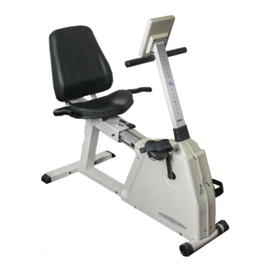
Vision Fitness R2000 Assembly Instruction Manual
Hide thumbs
Also See for R2000:
- Owner's manual (64 pages) ,
- Assembly manual (9 pages) ,
- Owner's manual (45 pages)
Advertisement
Quick Links
Download this manual
See also:
Owner's Manual
R2000
A S S E M B L Y I N S T R U C T I O N S
To avoid possible damage to this Fitness Cycle,
please follow these assembly instructions.
Carefully remove all its parts from the box,
lay them out and review the parts list.
If any parts are missing, please call 1-800-335-4348, Ext 12
Before proceeding, find your Fitness Cycle's serial number,
located on the underside of main frame, and enter here:
Refer to this number when calling for service.
I T
A L L
S T A R T S
W I T H
A
V I S I O N
Advertisement

Related Manuals for Vision Fitness R2000


Summary of Contents for Vision Fitness R2000
- Page 1 R2000 A S S E M B L Y I N S T R U C T I O N S To avoid possible damage to this Fitness Cycle, please follow these assembly instructions. Carefully remove all its parts from the box, lay them out and review the parts list.
- Page 2 R2000 Parts Diagram...
- Page 3 R2000 Parts VISION FITNESS R2000 Parts Description Part # Description Count Dimensions Rear Foot and Seat Support Parts #106 Rear Foot Assembly #182 Top Attachment Bolts 20mm L x 8mm D #184 Top Attachment Washers Bolt Plate Seat Rail Support Post...
- Page 4 R2000 Assembly Step 1 • Seat Support and Rear Foot Attach the Seat Rail Support Post (96) to the top of the Rear Foot Assembly (106) with four Bottom Support Post Bolts (186), four Washers (184) and Bolt Plate (91). Tighten with a 5mm allen wrench.
- Page 5 R2000 Assembly Step 3 • Seat Assembly 1: Secure the Seat Mount Handlebars (110) to the Seat Frame (115) with four Seat Attachment Bolts (182) and Washers (184). 2: When mounting the Seat Cushion Bottom (136), you have two sets of holes to choose from.
- Page 6 R2000 Assembly Step 4 • Pedals 1: Identify the left and right Pedals (152) and the left and right Pedal Straps(199). Attach the correct straps to each pedal, then thread each Pedal into the correct left and right crank arms and tighten.
- Page 7 R2000 Final Assembly Step 6 • Cable Connection 1: Locate the Tension Knob and upper cable assembly (130). Turn the Tension Knob to position 1. Reach inside the opening of the Console Mast (101) and connect the Upper Magnet Shift Cable (130) to the lower cable hook-slide on the end of the Lower Magnet Shift Cable (66), as shown in the accompanying illustrations.
- Page 8 621-D East Lake Street P.O. Box 280 Lake Mills, WI 53551 (920) 648-4090...