
Related Manuals for Fluke 830


Summary of Contents for Fluke 830
- Page 1 Laser Alignment Tool Users Manual July 2014 (English) © 2014 Fluke Corporation. All rights reserved. Specifications are subject to change without notice. All product names are trademarks of their respective companies.
- Page 2 Fluke authorized resellers shall extend this warranty on new and unused products to end-user customers only but have no authority to extend a greater or different warranty on behalf of Fluke. Warranty support is available only if product is purchased through a Fluke authorized sales outlet or Buyer has paid the applicable international price.
-
Page 3: Table Of Contents
4. FLUKE 830 – an overview ........ - Page 4 10. Appendix ............121 Using the sensor cable ....................121 Updating the 830 firmware to a newer version ..............124 Sensor firmware update ....................131 830 Laser Alignment Tool technical data ...............134...
- Page 5 List of figures Contents List of figures Figure 2-1. Items included with the Product ..............6 Figure 3-1. Laser safety warning ..................7 Figure 4-1. The Product at a glance ................13 Figure 4-2. Charging the non-removable rechargeable battery........16 Figure 4-3. Dismounting the charger plug ...............17 Figure 4-4.
- Page 6 Users Manual...
- Page 7 Contents List of tables Table 1-1. Symbols ......................3 Table 2-1. Package items ....................5 Table 4-1. The Product keyboard and display at a glance ..........14 Table 7-1. Measurement mode and relevant applications ..........68 Table 7-2. FLUKE 830 alignment condition LEDs ............72...
- Page 8 Users Manual...
-
Page 9: Preface
Introduction 1. Preface Introduction The Fluke 830 Laser Alignment Tool (Product) is a laser alignment device used in industrial environments for shaft alignment only. This user-friendly tool, which is used to determine the alignment condition of rotating machinery, features an alphanumeric keyboard with strategically placed navigation keys that handle all data entry functions. -
Page 10: Safety Information
Users Manual Safety information A Warning identifies conditions and procedures that are dangerous to the user. A Caution identifies conditions and procedures that can cause damage to the Product or the equipment under test. Warning To prevent eye damage and personal injury: •... -
Page 11: Table 1-1. Symbols
WEEE Directive Annex I, this product is classed as category 9 “Monitoring and Control Instrumentation” product. Do not dispose of this product as unsorted municipal waste. Go to Fluke’s website for recycling information. - Page 12 Users Manual Page intentionally left blank...
-
Page 13: Package
Table 2-1 is a list of all the items included in the purchase of the Product. The items are shown in Figure 2-1. Table 2-1. Package items Item Part Number Description Fluke 830 Laser Alignment Tool 4503893 Storage case 4462624 Sensor including dust cap and wireless module cable 4503893... -
Page 14: Figure 2-1. Items Included With The Product
Users Manual LASER ALIGNMENT TOOL SETUP MEASURE DIAGNOSE MENU PQRS WXYZ CLEAR ENTER space BACK Figure 2-1. Items included with the Product... -
Page 15: Safety And Operating Notes
Safety and operating notes Laser safety 3. Safety and operating notes The Product is to be used in industrial environments for shaft alignment only. Care must be taken to ensure that the Product is not subjected to mechanical knocks. It must be operated by properly trained personnel only. No liability will be assumed when components or operating procedures as described in this manual are not followed, or altered without permission of the manufacturer. -
Page 16: Operating Information
Users Manual Operating information Temperature range The Product and its related system components must be used at temperatures between 0° and 50° C (32° to 122° F). Outside of this range, the specified accuracy may not be maintained. Store the Product and its related components at temperatures between -20° C and 60°... - Page 17 It is strongly recommended that you keep a backup or printed records of all important data. FLUKE assumes no responsibility for data lost or altered as a result of improper use, repairs, defects, battery replacement/failures or any other cause.
-
Page 18: Handling Precautions
Users Manual Handling precautions The Product and its related components are precision instruments and should not be dropped or subjected to physical shock. Storage Use the supplied case to transport the Product and its related components. If the Product is not used for an extended period, remove the related batteries from the components and store the components in a cool, dry and well-ventilated location. - Page 19 Items that fall under this directive are marked with the shown crossed-out wheeled bin symbol and must be disposed of according to this directive. ● The marked components must be disposed of with FLUKE or their authorized disposal partners. ● Such parts must be taken to the nearest collection facility.
- Page 20 Users Manual Page intentionally left blank...
-
Page 21: Fluke 830 - An Overview
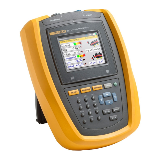
Overview Description 4. FLUKE 830 – an overview Description LASER ALIGNMENT TOOL SETUP MEASURE DIAGNOSE MENU PQRS WXYZ CLEAR ENTER space / . * BACK Figure 4-1. The Product at a glance... -
Page 22: Table 4-1. The Product Keyboard And Display At A Glance
Users Manual The Product at a glance Table 4-1. The Product keyboard and display at a glance Item Element Function The ‘Setup’ key opens the machine dimensions screen. SETUP The ‘Measure’ key is used to start the measure process. MEASURE The ‘Diagnose’... -
Page 23: Power Supply
Overview Power supply Power supply The Product is powered using a non-removable 7.4 V 2.6 Ah Lithium-ion polymer rechargeable battery, which is to be charged via the USB port only using the universal adapter/charger. The rechargeable battery allows operation of up to 17 hours (33% active measurement, 33% computation, 33% ‘sleep’... -
Page 24: Figure 4-2. Charging The Non-Removable Rechargeable Battery
Users Manual Charger/adapter is connected to the Product via the USB port. USB port (grey) Figure 4-2. Charging the non-removable rechargeable battery Note Before charging, the rechargeable battery should be discharged as much as possible. To charge the battery from 0% to 100% capacity takes approximately 4 hours. -
Page 25: Figure 4-3. Dismounting The Charger Plug
Overview Mounting/Dismounting universal adapter/charger plug Mounting and dismounting the universal adapter/charger plug The universal adapter/charger comes with three different regional plugs. The available plugs are for the Euro zone, the US, and the UK. When mounting or dismounting a plug, pay attention to the direction of the arrow on the plug just above the pins, and the arrow on the latching nipple on the charger housing. -
Page 26: Sensor
Users Manual To mount a plug, push the latching nipple in the forward direction [ ] as indicated by the arrow on it then slip the plug into the protruding prongs and slide it to the left until it latches. Sensor The sensor is mounted using the chain type bracket on the shaft or solid coupling of the stationary machine. -
Page 27: Figure 4-4. Parts Of The Sensor
Overview Sensor Green LED indicates Red LED indicates sensor is beam adjustment powered and laser is on laser is on Housing mark = center of bracket posts IP 67 housing Locking knob Scratch resistant lens Figure 4-4. Parts of the sensor Caution Avoid polishing the lens too vigorously to prevent irreparable damage to its anti-reflective coating. -
Page 28: Prism
Users Manual Prism The prism is mounted on the shaft or solid coupling of the machine to be moved. It reflects the laser beam back into the position detector as the shafts are rotated. The locking lever flips into the horizontal position, facing forward, to hold the prism in place on the bracket posts. -
Page 29: Mini Compact Chain-Type Bracket
Overview Mini compact chain-type bracket Mini compact chain-type bracket Compact and lightweight, this bracket is designed to provide extremely rigid support for the measurement components with a minimum of mounting time and effort. The chain-type bracket fits onto shafts and couplings ranging from 15 to 200 mm (1/2”... -
Page 30: Using The Wireless Module
Users Manual Using the wireless module The wireless module powers the sensor laser and passes alignment readings from the sensor to the Product. The module covers direct line of sight distances of up to 10 m / 33’ depending on the prevailing environmental conditions. Its electronic compartment complies with code IP65 (dust tight and protected against water jets). -
Page 31: Figure 4-7. Wireless Module On/Off Switch
Overview Wireless module Switch the wireless module on Wireless module ON/OFF switch Figure 4-7. Wireless module ON/OFF switch After connecting the sensor to the wireless module, switch the wireless module on (see Figure 4-7). The battery status LEDs blink for 3 seconds. The module is now ready for operation. - Page 32 Users Manual Page intentionally left blank...
-
Page 33: Configuration And Data Management
Configuration and data management Configuration 5. Configuration and data management Configuration The configuration menu is used to configure the Product’s settings, the regional settings, default settings, printer, licence available applications, and display specific system details. The configuration menu may be accessed at any time and from any screen. With the Product switched on, access “Configuration menu”... - Page 34 Users Manual Device settings To open the “Device settings” screen, use the navigation keys to highlight the ‘Device settings’ icon then confirm selection by pressing . The available ENTER settings are displayed. These include brightness, keyboard beep, power scheme, battery level, resume policy and Wireless. Use to select item to be set.
- Page 35 Configuration and data management Device settings The power scheme option is used to select setting that manages the power usage within the Product. The three available options are: ‘Standard’ (the display dims after 10 minutes and shuts down after 1 hour), ‘Full power’ (no dimming and no shutdown), and ‘Long life’...
- Page 36 Users Manual “Resume policy” allows the user to specify the measurement file that opens when the Product is turned on. The system may be set to open the last used measurement file (‘Always resume’) or open a new measurement file (‘Resume manually’).
- Page 37 Configuration and data management Regional settings Regional settings This option is used to set the units of measurement, the preferred country language, current date and time. Note The country language determines the format in which the date can be dis- played.
- Page 38 Users Manual and confirming selection by pressing Highlighting ‘Time zone’ using displays the different time zones. The required zone is selected using ENTER and confirmed by pressing ENTER When a time zone is initially highlighted, a hint appears displaying major world cities within the selected time zone.
- Page 39 Configuration and data management Regional settings Alternatively, use the data entry keys to set the date. With the required date component highlighted, enter the new date component using the data entry keys. On pressing the first key, the editing box appears. Enter value then confirm entry using either BACK ENTER...
- Page 40 Users Manual Pressing with ‘Date/time format’ highlighted reveals a menu box with the ENTER items ‘Date format’ and ‘Time format’. Use to select either item, confirming selection by pressing ENTER The time format is used to set either the 12h or 24h notation. The selected notation is confirmed by pressing ENTER The date format is used to set dd-mm-yyyy or mm/dd/yyyy format.
- Page 41 Configuration and data management Default settings Default settings To open the “Default settings” screen, use the navigation keys and highlight the ‘Default settings’ icon while in the configuration menu, then confirm selection by . The screen is used to set specific default parameters. Use pressing ENTER to cycle through the parameters.
- Page 42 Users Manual ● Tolerance table – the available options are 50 Hz and 60 Hz. The mains supply frequency determines the standard RPM values that appear in the tolerance table. Tolerance values based on these frequencies may be read off the suggested tolerance table.
-
Page 43: Data Management
Configuration and data management About application About application The information contained under this section is accessed by highlighting the ‘About’ icon while in the configuration menu screen. Confirm selection by pressing ENTER . The displayed information depicts the current status of the device and application. - Page 44 Users Manual to highlight any one of the four file and data management options. These are ‘Files list’, ‘Save file’, ‘Resume’ (or ‘New file’) and ‘Print report’. Note Note that the file menu items ‘Resume’ and ‘New file’ appear depending on the selected file resume policy which is set under the configuration item ‘Device settings’.
- Page 45 Configuration and data management Data management Note An existing file may be deleted by highlighting it using then press- . When a hint screen appears, use to highlight ‘Yes’. The CLEAR file is deleted by pressing to confirm deletion. ENTER To rename an existing file, use to highlight the file, then use the data entry keys to edit file name and confirm changes by pressing...
- Page 46 Users Manual ‘Print report’ – This option is used to print the measurement report or the soft foot measurement report. The following report options are available: ● Complete report – this option prints a complete report that includes machine graphics and measurement results in both numerical and graphical format. ●...
-
Page 47: Getting Started
The right LED 3. Switch the product on by pressing lights up followed by a beep. Shortly afterwards, the “Setup” screen appears. Enter dimensions Sensor Prism Left machine (stationary) Right machine movable Product FLUKE 830 Figure 6-1. Mounting components across the coupling... - Page 48 Users Manual Use the data entry keys to directly enter all required dimensions. The editing box and a hint text for the dimension to be entered or edited appears. to confirm entry. Use the data entry keys to enter this dimension then press ENTER The dimension arrows advance automatically to the next required dimension, and the corresponding hint text appears.
-
Page 49: Wireless Measurement
Getting started Wireless measurement Wireless measurement Note The measurement mode that will be described here is ‘Compass’ mode. In this mode, measurement points are taken at any 3 of the 8 available sectors. ‘Compass’ mode and ‘Clock’ modes are the default measurement modes for horizontal and vertical machines respectively. - Page 50 Users Manual Press then use the navigation keys and highlight the ‘Measure options’ MENU icon. Confirm selection by pressing . The “Measurement options” screen ENTER appears. Use the navigation keys and highlight the ‘Sensor selection’ icon, then confirm selection by pressing ENTER...
- Page 51 Getting started Wireless measurement and highlight ‘Scan’ then press to scan any wireless ENTER modules within the neighbourhood. Note Make sure the wireless module is switched on. Once detected, the wireless module is selected automatically. Adjust bracket if necessary to center beam horizontally onto the prism. Tighten bracket.
-
Page 52: Figure 6-3. Centering The Reflected Laser Beam Using
Users Manual Figure 6-3. Centering the reflected laser beam using the thumbwheel and the yellow beam adjustment knob Note When making the above adjustments, observe the product’s alignment condi- tion LED and the dot on the display screen. When the LED turns yellow, this is an indication that the reflected beam position is OK and measurement can proceed. -
Page 53: Diagnose
Getting started Diagnose Note Always turn shafts in the normal rotation direction of the machines. Rotate shaft to next measurement position and take point. Readings from any 3 of the 8 available positions (taken in any order) are required for results, which are initiated automatically after the set measurement points have been taken. - Page 54 Users Manual The foot results show the foot correction values relative to the stationary machine. In foot results positive values indicate that right machine is downwards (therefore add shims for correction) or towards viewer (therefore move away from viewer for correction). Negative values indicate that movable machine is upwards (therefore remove shims for correction) or away from the viewer (therefore move towards viewer for correction).
-
Page 55: Horizontal Machine Alignment
Horizontal shaft alignment Job preparation 7. Horizontal machine alignment Preparing for the alignment procedure Before using the Product, prepare the machine for alignment as described below. Warning Make sure machines are locked out and tagged out and cannot be started accidentally or deliberately while you are working on them! Solid, flat foundation A solid, rigid foundation is required to obtain correct, lasting shaft alignment that allows long-term uninterrupted machine service. -
Page 56: Check For Soft Foot
Users Manual Measurement separation Since the Product requires no mechanical connections (such as cantilevered dial indicator brackets) to span over the coupling during measurement, alignment may easily be performed over large sensor–prism separations. Note that over very large distances the shafts and coupling may sag, and the machines may need to be deliberately misaligned to take the catenary curve into account, if such sag does not disappear when machines are put into operation. -
Page 57: Figure 7-1. Mounting The Bracket Step-By-Step
Horizontal shaft alignment Mount brackets 2. Fasten the support posts in place by tightening the hex screws on the sides of the bracket frame. 3. Place the bracket on the shaft or coupling. Wrap the chain around the shaft and feed it through the other side of the bracket: If the shaft is smaller than the width of the bracket frame, insert the chain from the inside of the bracket as shown in Figure 7-1;... -
Page 58: Mount Wireless Module, Sensor And Prism
Users Manual Mount wireless module, sensor and prism 1. Mount the wireless module on the support posts of the bracket fixed on the shaft of the left machine (usually stationary machine) – as viewed from normal working position. The module fastens on the support posts. It is recommended to slide the wireless module all the way down onto the bracket frame (see Figure 7-2). -
Page 59: Figure 7-2. Mounting Wireless Module And Sensor
Horizontal shaft alignment Mount wireless module, sensor and prism The wireless module slides Fasten the sensor onto the onto the support posts and support posts by tightening is held in place by friction the yellow knobs fit. The 90-degree sensor cable connector is attached to the wireless module... -
Page 60: Connect The Sensor
Users Manual Arrow Match the height of the yellow knob approximately to the tip of the arrow Figure 7-4. Centering prism knob for maximum adjustment Proceed to ‘Switch Product on and start application’ on page 47. If using the sensor cable for data transmission, see ‘Connect the sensor’ below. Connect the sensor Note Measurement data may also be transmitted from the sensor to the Product... -
Page 61: Switch Product On And Start Application
Horizontal shaft alignment Start application Figure 7-5. Inserting sensor cable into the alignment tool Disconnecting the sensor cable To disconnect, grasp the ribbed collar of the sensor plug and carefully pull it out of the computer sensor port. Switch Product on and start application Press and hold down for a few seconds. -
Page 62: Enter Machine Dimensions
Users Manual Enter machine dimensions Machine dimensions are entered using the grey data entry keys. An editing box and a hint text for the dimension to be entered or edited appear on the dimensions screen. The required missing dimensions are entered directly using the data entry keys. -
Page 63: Figure 7-6. Machine Dimensions To Be Entered
Horizontal shaft alignment Enter dimensions Enter dimensions as shown in Figure 7-6: Figure 7-6. Machine dimensions to be entered Sensor to prism This is the distance between the markings on top of the sensor and the prism (refer to Figure 7-7). The dimension is determined by measuring the distance between the center of the prism and the sensor support posts. - Page 64 Users Manual Sensor to coupling center This is the distance between the marking on top of the sensor and the coupling center. This dimension is calculated automatically as half the entered sensor to prism distance. The value may be edited directly in the editing box that appears and value confirmed by pressing ENTER Coupling diameter...
-
Page 65: Figure 7-8. Distance Marking On The Sensor
Horizontal shaft alignment Entering negative dimensions Entering negative dimensions In certain circumstances or unusual machine configurations, negative dimensions may also be entered where needed, such as coupling center to front foot (right machine) when this foot is behind the coupling center, or sensor to coupling center if the sensor is mounted on the coupling such that the sensor distance marking is in front of the coupling as shown in Figure 7-8. -
Page 66: Machine Set-Up
Users Manual Machine set-up Machine properties may be set via the menu items ‘Left machine’ or ‘Right machine’. The menu screen is accessed by pressing MENU Use the navigation keys and highlight either ‘Left machine’ or ‘Right machine’ icon. Pressing with the left or right machine icon highlighted, reveals the ENTER machine properties that may be edited. - Page 67 Horizontal shaft alignment Coupling tolerance table to highlight machine parameter to be changed and confirm selection by pressing ENTER Coupling tolerance table With ‘Coupling Tol.’ icon highlighted, pressing reveals the coupling ENTER tolerance table. The highlighted RPM is the value entered in the “Set-up” screen. A different RPM value may be set from the “Tolerance table”...
-
Page 68: Laser Beam Adjustment
Users Manual and highlight ‘Yes’ then confirm selection by pressing ENTER The new RPM value overrides the value initially entered during set-up. Coupling tolerances will now be based on this accepted RPM value. Laser beam adjustment After entering all required dimensions, the measurement screen appears auto- matically. - Page 69 Horizontal shaft alignment Laser beam adjustment Remove sensor cap Warning Do not stare into beam. The laser beam is now on! Leave the prism cap on. When the beam strikes the cap it should be readily visible. Should the beam be so far off target that it misses the prism completely, hold a sheet of paper in front of the prism to try and locate the beam.
- Page 70 Users Manual Confirm selection by pressing . The selection window appears. ENTER Use either and highlight ‘Scan’ then press to scan wireless ENTER modules within the neighbourhood. Once detected, the module is automatically connected and communication established between the sensor and the Product. If using the sensor interface, use either and highlight “Port 1 to confirm selection, and proceed with laser beam adjustment.
- Page 71 Horizontal shaft alignment Wireless communication Note The serial number of the wireless module in use is displayed on the screen during measurement. Now proceed with laser beam adjustment. All detected wireless modules are remembered by the Product, and are displayed when ‘Sensor selection’...
- Page 72 Users Manual It may be necessary to delete some of these entries as they could no longer be in use. To delete unwanted entries, access the ‘Sensor selection’ menu. Use the navigation keys to highlight the wireless module to be deleted and press CLEAR Wireless modules deleted are remembered if detected during scanning.
-
Page 73: Figure 7-9. Horizontal And Vertical Adjustment Of The Laser Beam
Horizontal shaft alignment Laser beam adjustment Adjust prism until ONLY the GREEN sensor LED lights constantly, the Product’s right LED turns blue The sensor has a red and a green LED to indicate the beam adjustment condition. This condition is simultaneously monitored on the Product’s alignment condition LED (right LED). - Page 74 Users Manual Center beam such that the Product’s right LED turns blue Adjust the laser beam such that the laser dot on the display screen is positioned in the green square in the center of the detector display. ● Horizontal adjustment with yellow prism knob ●...
- Page 75 Horizontal shaft alignment Laser beam adjustment GREEN sensor LED blinks slowly and the Product’s RIGHT LED turns GREEN Note The red arrow on the yellow knob assists the user by indicating which way the knob should be turned. The closer the beam comes to being centered, the smaller this arrow becomes When the laser beam is inside the center square, the GREEN sensor LED lights constantly.
-
Page 76: Take Measurements
Users Manual Take measurements It is important to note which measurement mode is best suited for a particular application. The table below gives a guide as to which measurement mode is ideal for which measurement. Table 7-1. Measurement mode and relevant applications Measurement mode Application Compass mode... - Page 77 Horizontal shaft alignment Turning shafts Turning shafts To measure, rotate shaft to the first measurement position. Measurement can only be taken when the sector in which the shaft has been positioned is to take the first measurement point. The sector is highlighted green.
-
Page 78: Diagnose
Users Manual Note Remember not to touch mounted components! This includes the brackets and the support posts, which are NOT to be used to rotate the shafts . It is advisable to turn shafts in the same direction as the machine normally rotates, in case the shafts shift from their normal seating in the bearings. - Page 79 Horizontal shaft alignment Diagnose Alignment condition in both vertical and horizontal directions The coupling diagnosis is given in the form of gap and offset values in both vertical and horizontal directions. The true gap being the difference in gap between the coupling faces top to bottom (vertical) or side to side (horizontal) at the diameter that was entered.
-
Page 80: Figure 7-10. Tolerance Bar
Excellent tolerance Acceptable tolerance Out-of-tolerance Grossly misaligned Figure 7-10. Tolerance bar The Product’s alignment condition LED provides additional information on the tolerance status. Table 7-2. FLUKE 830 alignment condition LEDs Tolerance Tolerance bar LED color Excellent tolerance Green LASER ALIGNMENT TOOL... -
Page 81: Align Machine
Horizontal shaft alignment Aligning machine Tolerance table Note Suggested alignment tolerances are based upon experience and should not be exceeded. They are to be used only if existing in-house standards or the manufacturer of the machine or coupling prescribe no other values. The tolerance table is accessed as described under ‘Coupling tolerance table’... - Page 82 Users Manual Loosen bolts Avoid moving the machine horizontally. If any foot comes off the ground when loosened, suspect soft foot. Shim feet accordingly Shimming usually involves the jacking up of the machine and inserting or removing shims of known thicknesses. (Some shims have the thicknesses indelibly etched on them.) Use the vertical foot correction values to shim BOTH front and back feet as required.
- Page 83 Horizontal shaft alignment Live Move Start live horizontal Move While in results screen, press The “Main menu” window opens. ENTER MENU to confirm Use the navigation keys and highlight the ‘Move’ icon then press ENTER selection. The screen used to position the sensor in any of the four appropriate 45°...
- Page 84 Users Manual Use either to highlight “Horizontal” for horizontal machine movement. Confirm selection by pressing . Live Move starts as soon as the direction of ENTER movement has been confirmed. Loosen bolts and move machine as required After loosening the anchor bolts, move the machine feet in the direction of the apex of the yellow triangles, keeping an eye on the marking on the color-coded tolerance bar.
- Page 85 Horizontal shaft alignment Live Move When the marking on the color-coded tolerance bar is on either the green or yellow section, the alignment condition is within tolerance. Proceed to tighten the anchor bolts. Tighten the anchor bolts Tighten anchor bolts, then press to recheck the alignment ENTER BACK...
- Page 86 Users Manual Saving data and printing (Refer to page 81.) Finally Switch the Product off, and then remove the components from the shafts, and store them in the case. Warning Replace guards before you switch the machine back on. Vertical live Move Note As it is recommended to first shim, and then move the machine laterally, the vertical live Move function may be used to carry out the shimming.
- Page 87 Horizontal shaft alignment Points to observe during the Move Points to observe during the Move Closely observe all the following points: Have shafts accidentally moved (rotated)? The shafts, sensor and prism MUST remain steady during the entire Move procedure. Should the shaft move from the set 45° green sector while in Move, the angle selection screen comes up indicating the angle to which the shaft has rotated.
- Page 88 Users Manual Soft foot If the machine suffers from excessive soft foot, the Move function may be hampered by the fact that the machine changes its position on its own every time the bolts are loosened and tightened. Correct this problem before aligning. (Refer to page 92.) If poor repeatability is experienced Possible causes include:...
-
Page 89: Saving Data And Printing
Horizontal shaft alignment Saving data and printing Saving data and printing Before switching off the instrument, dimensions, measurements, diagnosis and all settings can be saved for analysis, future use or record purposes in the instrument’s non-volatile memory. Full file names with up to 32 alphanumeric characters are possible. - Page 90 Users Manual and highlight the “Save file” icon then confirm selection by pressing . An empty editing box appears within the “Save file” screen. ENTER When entering names that contain both upper and lower case characters as well / . * as numerals, use to cycle through the three options.
- Page 91 Horizontal shaft alignment Saving data and printing In this particular example, the file “ACME-123” had previously been saved and therefore the name appears highlighted in the editing box. to save the measurement results under the displayed file name. A Press ENTER hint requiring confirmation whether to overwrite the existing file appears.
- Page 92 Users Manual Printing reports Using the default printer type ‘PDF file’, measurement reports may be saved directly to the connected USB memory stick as a PDF, and then printed from any configured printer. Reports can also be printed directly from the Product to a printer. This is done using the USB cable and the printer USB cable (supplied with the printer or readily available in most electronics stores).
-
Page 93: Figure 7-11. Saving Measurement Report As Pdf On A Memory Stick
Horizontal shaft alignment Printing reports The Product provides the option of printing reports in the following three formats: ● Complete report – this option prints a complete report that includes machine graphics and measurement results in both numerical and graphical format. ●... - Page 94 Users Manual Configuring printer If it is desired to print the report directly from the Product, the printer settings must be set accordingly. This can be carried out from the menu. Press MENU use the navigation keys and highlight the ‘Config’ icon. to confirm selection.
- Page 95 Horizontal shaft alignment Available printing options Available printing options The “Printer configuration” screen shows the options that can be selected. Use either to highlight the printer setting to be changed. In the preceding example, the printer setting selected is printer type, and the currently set printer type is the default –...
-
Page 96: Figure 7-12. Printing Measurement Report From Product Directly To Desired Printer
Users Manual Note Ensure the Product is connected to the printer via the short USB cable and the printer USB cable (supplied with the printer or readily available in most electronics stores) and the printer configuration completed. Printer USB cable Short USB cable Figure 7-12. - Page 97 Horizontal shaft alignment Available printing options Note When printing a report directly to a printer, the “Print report” screen provides an option to change to the default printer ‘PDF file’. The printer setting ‘Paper’ is used to select paper size. With ‘Paper’ highlighted, press then use to scroll through the available paper sizes.
- Page 98 Users Manual With the setting ‘Color mode’ highlighted, press then use ENTER select the color in which the report will be printed. Selecting ‘Color’ results in full color reports, while ‘Gray scale’ results in black and white reports. Note Note that with the three printer settings ‘Paper’, ‘Orientation’ and ‘Color mode’, it is possible to toggle between the two available options using For example if the setting ‘Paper’...
-
Page 99: Soft Foot
Horizontal shaft alignment Soft foot Soft foot Soft foot is the condition of machine frame distortion. Any cause that results in machine frame distortion when the machine is anchored to its foundation is a soft foot. Some of the principal causes are: ●... -
Page 100: Main Types Of Soft Foot
Users Manual Main types of soft foot The three main types of soft foot are parallel soft foot, angular soft foot, and induced soft foot. Parallel soft foot One or more feet do not reach the foundation. This usually results in the machine leaving a gap between the foundation and the feet. - Page 101 Horizontal shaft alignment Checking soft foot conditions to confirm selection. Press ENTER Once sensor initialization is completed and provided the laser beam was correctly centered ( see ‘Laser beam adjustment’ in chapter 7) the ‘Laser READY’ hint appears on the Product’s display.
- Page 102 Users Manual to confirm Use the navigation keys to select the foot to be measured. Press ENTER foot selection. Note the hint on the screen carefully. After selection of the foot to be measured, pressing activates the process of identifying foot to be measured. ENTER After foot to be measured has been identified, the value +0.00 appears in its value box plus a hint indicating that the foot anchor bolt may be loosened.
- Page 103 Horizontal shaft alignment Checking soft foot conditions The calculated amount that the foot has moved is shown on the screen. Retighten the bolt. The next foot is highlighted automatically, or any desired foot can be selected using the navigation keys. Repeat this procedure for each foot.
-
Page 104: Points To Be Observed During Soft Foot Measurement
Users Manual Points to be observed during soft foot measurement Laser beam not centered If initially the laser beam has not been centered, the following screen appears. Use the on-screen instructions to adjust the laser beam. You may refer to ‘Laser beam adjustment’... - Page 105 Horizontal shaft alignment Points to observe during soft foot measurement Dimension missing Note If however, either of the two significant machine dimensions, “front foot-to- back foot” and “sensor-to-prism”, are missing, the following hint appears. and highlight ‘Yes’, confirming selection by pressing .
- Page 106 Users Manual When the message “angle in range” appears, you may press ENTER BACK continue with soft foot measurement. Alternatively, you may wait for the process to resume automatically. Note If the soft foot procedure is followed correctly, the above mentioned points will not arise.
-
Page 107: Figure 7-14. Diagnosis Of Parallel And Angular Soft Foot
Horizontal shaft alignment Correcting soft foot 0.18 0.89 0.18 0.13 0.74 0.10 0.76 0.10 Angular soft foot Parallel soft foot Figure 7-14. Diagnosis of parallel and angular soft foot... - Page 108 Users Manual Page intentionally left blank...
-
Page 109: Alignment Options
Alignment options Measurement modes 8. Alignment options Measurement modes The Product’s default measurement modes are Compass mode (for horizontal mounted machines) and Clock mode (for vertical mounted machines). Both measurement modes may be accessed via the menu. Note The respective default mode is automatically present when the “Measure” screen is accessed after entering all necessary machine dimensions. - Page 110 Users Manual Note The “Measurement options” screen is accessible only when all necessary machine dimensions, in the currently opened measurement file, have been entered. Using the navigation keys, highlight the required measurement mode, and then to confirm selection. press ENTER In the above case, the selected measurement mode is the ‘Clock’...
- Page 111 Alignment options Extend 2. Press to access the “Main menu” screen. While in the menu screen use MENU the navigation keys and highlight the ‘Measure options’ icon and then confirm selection by pressing . The “Measurement options” screen opens. ENTER 3.
- Page 112 Users Manual 4. Readjust the beam into the target square using the yellow prism knob and the metal thumbwheel. 5. On centering the laser dot, the Product’s right LED turns blue. The adjusted LASER ALIGNMENT TOOL beam position is automatically recorded and taken as the end point of the readjustment.
- Page 113 Alignment options Averaging Use the navigation keys to highlight the ‘Averaging’ icon, then press ENTER confirm selection. The average setting can be changed from a minimum averaging of 0.5 seconds to a maximum averaging of 5.0 seconds. Note The averaging setting that is selected will also be active in soft foot and Move. Should high averaging be selected, patience must be exercised during Move to allow the Product enough time to “catch-up”as the machine is moved.
- Page 114 Users Manual Page intentionally left blank...
-
Page 115: Vertical Flanged Machines
Vertical flanged machines Typical configuration 9. Vertical flanged machines Typical configuration Typical vertical machine arrangement comprised of one machine mounted on top of the other with a bolted flange. Figure 9-1. Typical vertical machine configuration Figure 9-1 shows a typical vertical machine arrangement with one machine mounted on top of the other using a bolted flange. -
Page 116: Set-Up
Users Manual Set-up Note Before commencing with this section, please acquaint yourself with the chap- ter ‘Horizontal machine alignment’ starting on page 47. The sensor and prism are mounted on either side of the coupling as for horizontal machines, with the sensor on the bottom half (‘Stationary’) and the prism on the upper half (‘Movable’). -
Page 117: Figure 9-3. Numbering The Housing
Vertical flanged machines Mounting components For circular housings, measure the circumference of the coupling housing and divide by eight. Use this distance to make eight evenly-spaced marks on the housing beginning at your chosen start point. Number the points clockwise looking down onto the shaft with 0 as the first, followed by 1:30, 3:00, 4:30, 6:00, 7:30, 9:00 and 10:30. - Page 118 Users Manual to confirm selection then use the navigation keys and highlight 4. Press ENTER the ‘Change to flange’ icon. to confirm selection. The “Edit flange” screen appears. This 5. Press ENTER indicates a vertical machine orientation.
- Page 119 Vertical flanged machines Editing flange configuration Editing flange configuration A typical vertical machine train arrangement consists of machines mounted together using a bolted flange. To configure the flange proceed as follows: 1. Once in the “Edit flange” screen use the navigation keys to cycle through the flange pattern parameters that may be edited.
- Page 120 Users Manual 4. Use the navigation keys to highlight the desired flange configuration, pressing to confirm selection. ENTER 5. To edit the dimensions of the selected flange pattern, use the navigation keys to highlight dimension to be edited, then enter value directly using the data entry keys.
- Page 121 Vertical flanged machines Enter dimensions 7. To edit the number of flange bolts, use the navigation keys to highlight ‘Number of flange bolts:’ With the button ‘Number of flange bolts:’ highlighted, edit value directly using the data entry keys then confirm value by pressing either ENTER BACK Enter dimensions...
- Page 122 Users Manual 2. Enter the coupling diameter. The default is 100 mm (10” if units option is set to imperial units.) 3. Enter the RPM. The default is 1500. (1800 if units option is set to US customary units.) 4. Enter the coupling center-to-flange distance.
- Page 123 Vertical flanged machines Measure Measurements can now be made. Measure 1. Switch the wireless module on to power the sensor. Press then MEASURE proceed to adjust the laser beam and establish wireless communication as described in the respective sections in Chapter 7 ‘Horizontal machine alignment’.
- Page 124 Users Manual to take the first measurement point. 4. Press ENTER Note After taking measurement point, the clock hour hand moves automatically to the next clock position. (If the first measured position is 12:00 o’clock, then the hour hand moves to the 1.30 o’clock position). 5.
- Page 125 Vertical flanged machines Diagnose Diagnose When measurement is complete, press to view the diagnosis. DIAGNOSE Note Sign convention (for vertical machines) POSITIVE GAP opens towards 0:00 or 3:00 POSITIVE OFFSET if the top coupling half is offset towards 0:00 or 3:00 Cycle through the coupling results and the flange corrections by pressing DIAGNOSE repeatedly.
- Page 126 Users Manual Pressing the navigation keys long enough or changes the bolt correction value mode. The following options are available: ● Bolt correction (+): means all shimming corrections are positive (add shims) ● Bolt correction (-): means all shimming corrections are negative (remove shims) ●...
- Page 127 Vertical flanged machines Correcting offset 2. Confirm selection by pressing ENTER 3. On confirmation the screen used to position the sensor and prism for optimal moves appears. 4. Rotate shaft to any of the four positions highlighted in green. These are 1:30, 4:30, 7:30 and 10:30.
- Page 128 Users Manual 8. Loosen the flange bolts. Move the machine laterally in the direction of the yellow triangle as indicated in the Live Move display. 9. Corrections should be brought as close as possible to zero. The marking on the color-coded tolerance bar should change from red to orange to yellow and finally green.
-
Page 129: Appendix
Appendix Using the sensor cable 10. Appendix Using the sensor cable If you need to use the sensor cable (due to flat batteries in the wireless module) then it must be properly attached to the sensor. To attach the sensor cable proceed as follows: Open the front of the sensor housing Unscrew the left-hand locking knob as shown in Figure 10-1, then lift off the front... -
Page 130: Figure 10-2. Fastening The Sensor Cable
Users Manual Figure 10-2. Fastening the sensor cable Caution Never turn the plug itself, as that can damage the cable pins. Carefully thread the cable into its guide grooves as shown in Figure 10-2. Ensure the cable remains in place. Close the sensor housing Return the front portion of the sensor housing to its position, then retighten the yellow locking knob into place. - Page 131 MEASURE indicator LED of the sensor should blink to indicate beam emission. If not, ensure that the sensor cable has been properly connected; otherwise, contact FLUKE. Note Both sensor and wireless module cables may be replaced in the same manner...
-
Page 132: Updating The 830 Firmware To A Newer Version
● The Product firmware updates are carried out with the use of the approved FLUKE USB memory stick. ● Check the website www.fluke.com to ensure you have the latest version. If in doubt, contact FLUKE. ● If you are acquiring the update via the website, you will be required to transfer it to the approved memory stick before commencing the upgrading. - Page 133 Appendix Carrying out the firmware update After selecting the location of the approved memory stick by clicking ‘Browse‘, start file extraction by clicking ‘Extract‘. Carrying out the firmware update The firmware update is carried out using the memory stick and the ‘short’ USB cable.
- Page 134 Users Manual 1. Press to switch the Product on. Wait for the “Setup” screen to appear. Note Before proceeding with the update ensure that the indicated nominal capacity of the battery is greater than 50%. If this is not the case, recharge the battery to full capacity first.
-
Page 135: Figure 10-3. Memory Stick Connected To The Product Using The 'Short' Usb Cable
Appendix Carrying out the firmware update Figure 10-3. Memory stick connected to the Product using the ‘short’ USB cable 4. A hint indicating the availability of a new firmware and the need to reboot the Product appears. - Page 136 Users Manual 5. When the hint above appears, press and hold down until the device reboots. The display goes dark. 6. The update process will start automatically (wait up to 10 seconds). The system beeps and the right LED flashes as the process begins. Note Do NOT turn off the device or remove the memory stick during the entire up- date process, which takes up to 5 minutes.
- Page 137 Appendix Carrying out the firmware update 9. When the hint above appears, press and hold down until the device reboots, and the “Setup” screen appears. Note The ‘short’ USB cable may now be detached from the Product. 10. When the “Setup” screen appears, press .
- Page 138 Users Manual 11. Use the navigation keys and highlight the ‘About’ icon. With the icon highlighted, confirm selection by pressing . The “Application details” ENTER window appears. The Product is now ready for use with the uploaded version which may be identified from the “Application details”...
-
Page 139: Sensor Firmware Update
Appendix Sensor firmware update Sensor firmware update If a sensor with an older firmware version is connected to the Product, a hint indicating that the sensor firmware requires updating appears on the display. to confirm and select ‘Yes’ to update the sensor. Press ENTER selection. - Page 140 Users Manual to confirm selection. and highlight ‘Next’ then press ENTER Note Ensure that at least two battery status LEDs on the wireless module light up continuously. This guarantees enough operating time for the sensor firmware update. A further hint to ensure proper connection of the wireless module to the sensor appears on the screen.
- Page 141 Appendix Sensor firmware update Once the sensor firmware update is finalised, the final update screen appears. Restart the Product. Note The sensor firmware update may also be carried out using the sensor cable. The sensor should be attached to the Product using the sensor cable as shown in Figure 7-5.
-
Page 142: Laser Alignment Tool Technical Data
Users Manual 830 Laser Alignment Tool technical data Product Intel XScale PXA270 running at 312 MHz Memory 64 MB RAM, 32 MB Flash Display Type: TFT, transmissive (sunlight-readable), 65 535 colours, backlit Integrated light sensor for automated adjustment of the brightness... -
Page 143: Technical Data
Appendix Technical data Prism Particulars Type: 90° roof prism Accuracy (avg): > 99% Environmental protection: IP 67 (submersible, dustproof) Storage temperature: -20°C to 80°C [-4°F to 176°F] Operating temperature: -20°C to 60°C [-4°F to 140°F] Dimensions: approx. 100 x 41 x 35 mm [4” x 1 5/8” x 1 3/8”] Weight: approx. -
Page 144: Suggested Shaft Alignment Tolerances
Users Manual Suggested shaft alignment tolerances [RPM] metric [mm] inch [mils] Soft foot 0.06 mm 2.0 mils Short “flexible” Acceptable Excellent Acceptable Excellent couplings Offset 0.19 0.09 1200 1500 0.09 0.06 1800 3000 0.06 0.03 3600 6000 0.03 0.02 7200 Angularity 15.0 10.0... -
Page 145: Declaration Of Conformity
Appendix Declaration of conformity Declaration of conformity Note Any amendments to the issued certificate will be posted on the FLUKE web- site – www.fluke.com. Please visit the website on a regular basis for information on new and current products. - Page 146 Users Manual Page intentionally left blank...
-
Page 147: Index
Index Index Extend 79 Alignment condition LED 44, 72 measurement range 70 Averaging 104 Extending measurement range 102 Bar scale green 40 File Battery capacity 27 overwrite name 83 Bolt correction 118 save 81 Brackets Firmware mounting 48 downloading 124 update procedure 125 Firmware update 124 Flange configuration... - Page 148 Power scheme 27 Symbols 3 Printer configure 86 Printer configuration 34 Printing options 87 Technical data Printing reports 84 830 Laser Alignment Tool 134 Prism 20 Tolerance bar 46 mounting 50 colour-coded 72, 95 Prism knob 52 marker 95 marking 72...
- Page 149 Index Wireless module 22 delete 64 LED indicators 23 mounting 50 scan 62 Wireless module cable 121...
- Page 150 Users Manual...