Table of Contents
Advertisement
Safety Depends on You
Lincoln arc welding and cutting
equipment is designed and built
with safety in mind. However, your
overall safety can be increased by
proper installation ... and thought-
ful operation on your part. DO
NOT INSTALL, OPERATE OR
REPAIR THIS EQUIPMENT
WITHOUT
READING
MANUAL AND THE SAFETY
PRECAUTIONS CONTAINED
THROUGHOUT. And, most
importantly, think before you act
and be careful.
World's Leader in Welding and Cutting Products
Sales and Service through Subsidiaries and Distributors Worldwide
22801 St. Clair Ave. Cleveland, Ohio 44117-1199 U.S.A. Tel. (216) 481-8100
RETURN TO MAIN INDEX
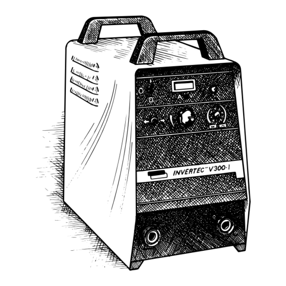
INVERTEC V300-I
For use with machines Code Numbers
THIS
SERVICE MANUAL
9826
9827
10036
10037
10132
10133
Premier Manufacturer of Industrial Motors
SVM101-A
December 1995
Advertisement
Chapters
Table of Contents
Troubleshooting

Related Manuals for Lincoln Electric INVERTEC V300-I


Summary of Contents for Lincoln Electric INVERTEC V300-I
- Page 1 SVM101-A RETURN TO MAIN INDEX December 1995 INVERTEC V300-I 9826 For use with machines Code Numbers 9827 10036 10037 10132 10133 Safety Depends on You Lincoln arc welding and cutting equipment is designed and built with safety in mind. However, your overall safety can be increased by proper installation ...
-
Page 2: Electric Shock Can Kill
Miami, Florida 33135 or CSA Standard W117.2-1974. A Free copy of “Arc Welding Safety” booklet E205 is available from the Lincoln Electric Company, 22801 St. Clair Avenue, Cleveland, Ohio 44117-1199. BE SURE THAT ALL INSTALLATION, OPERATION, MAINTENANCE AND REPAIR PROCEDURES ARE PER- FORMED ONLY BY QUALIFIED INDIVIDUALS. - Page 3 This can create fire hazards or overheat lifting chains recommendations. or cables until they fail. 6.c. Ground the equipment in accordance with the U.S. National 4.h. Also see item 7c. Electrical Code and the manufacturer’s recommendations. Mar. ‘93 INVERTEC V300-I...
-
Page 4: Safety
___________________________________________________ 7.h. To avoid scalding, do not remove the radiator pressure cap when the engine is hot. INVERTEC V300-I... - Page 5 Se protéger avec des vêtements de protection libres de l’huile, tels que les gants en cuir, chemise épaisse, 4. Garder tous les couvercles et dispositifs de sûreté à leur pantalons sans revers, et chaussures montantes. place. Mar. ‘93 INVERTEC V300-I...
-
Page 6: Table Of Contents
Troubleshooting Guide....................F-3 Test Procedures Capacitor Replacement ..................F-50 Switch PC Board Replacement................F-54 Test After Repair of Switch Boards and/or Capacitors .........F-56 Output Diode Replacement...................F-58 Input Filter Capacitor Conditioning................F-59 Environmental Protection..................F-59 Retest After Repair ....................F-60 Electrical Diagram ....................Section G Parts Manual INVERTEC V300-I... - Page 7 High Frequency Precautions ..................A-2 Input Connections....................A-2 Ground Connections ..................A-3 Input Power Cord Connection.................A-3 Input Power Connection .................A-3 Input Fuse and Supply Wires................A-3 Input Voltage Reconnect Procedure ...............A-3 Output Connections ....................A-4 Work and Electrode Cable Connections ............A-4 Amphenol Receptacle..................A-4 INVERTEC V300-I...
-
Page 8: Installation
10 (6mm 440/50-60 10 (6mm 10 (6mm PHYSICAL DIMENSIONS Height Width Depth Weight 18.7 in. 10.8 in. 22.2 in. 64 lbs. 475 mm 274 mm 564 mm 29 Kg (1) Input voltage must be within ±10% of rated value. INVERTEC V300-I... -
Page 9: Location
ON/OFF POWER SWITCH SELECT SUITABLE LOCATION 14 PIN AMPHENOL INPUT CORD 6 AMP BREAKER NOTE: The Invertec V300-I is capable of operating in ACCESS HOLE 115 V CIRCUIT 2 AMP BREAKER harsh environments. However, it is important to use 42 V CIRCUIT... -
Page 10: Ground Connections
CONNECTOR 1. To connect 200/220/380-415/440 AC MULTIPLE voltage machines, follow procedures shown below NOTE: The Invertec V300-I is supplied with one cord and refer to Figure A.2. connector. The cord connector provides a strain relief for the input power cord as it passes through the right 2. -
Page 11: Output Connections
The 14 Pin Amphenol is used to connect various 100% 1/0 (50mm 1/0 (50mm options and accessories to the V300-I. Refer to the 1/0 (50mm 2/0 (70mm Accessory Section of this manual for available acces- sories and connection instructions. INVERTEC V300-I... -
Page 12: Operation...........................................................................................................section B Safety Precautions
TABLE OF CONTENTS - OPERATION SECTION - Operation......................Section B Safety Precautions....................B-1 General Description ....................B-2 Recommended Processes and Equipment ...........B-2 Operational Features and Controls..............B-2 Welding Capability ..................B-2 Limitations......................B-2 Controls and Settings ....................B-2 Welding Operation ....................B-4 Auxillary Power ......................B-5 Overload Protection ....................B-5 INVERTEC V300-I... -
Page 13: Operating Instructions
• Keep flammable material away. • Do not weld on containers that have held combustibles. ARC RAYS can burn. • Wear eye, ear and body protection. Observe additional Safety Guidelines detailed in the beginning of this manual. INVERTEC V300-I... -
Page 14: Operation
OPERATION GENERAL DESCRIPTION OPERATIONAL FEATURES AND CONTROLS The Invertec V300-I is a 300-amp arc welding power The Invertec V300-I provides continuous total range source that utilizes single- or thee-phase input power output current or voltage adjustment, selectable weld- to produce either constant voltage or constant current ing modes and local or remote output control. - Page 15 10 = highest pinch, lowest inductance, and most spatter. • CV FCAW — This setting has been optimized for Innershield ® and Outershield ® flux-cored elec- trodes. XX refers to tensile strength of electrode (i.e., 60, 70, etc.). INVERTEC V300-I...
-
Page 16: Welding Operation
CONSTANT VOLTAGE PROCESSES Gas Metal Arc Welding (GMAW) GMAW welding may be performed with the Invertec using the Lincoln Electric LN-9 GMA, LN-25 or LN-7 Wire Feeders. An appropriate GMAW gun and cable assembly and a regulated supply of shielding gas are required. -
Page 17: Overload Protection
AUXILIARY POWER Three AC auxiliary power supplies are included in the Invertec V300-I: 24 VAC, 42 VAC and 115 VAC. The 24 VAC supply is rated at 1 amp and provides power for the LN-25 wire feeder. Protection is provid- ed by a self-resetting current limited. -
Page 18: Accessories.......................................................................................................section C Options/Accessories
- ACCESSORIES SECTION - Accessories.......................Section C Options/Accessories....................C-1 Connecting a LN-25 Wire Feeder................C-2 Connecting a LN-7 Wire Feeder................C-4 Connecting a LN-9 GMA Wire Feeder..............C-6 Connecting Other Wire Feeders................C-8 Connecting a K900-1 DC TIG Starter..............C-11 Connecting for Parallel Operation ...............C-12 12/95 INVERTEC V300-I... -
Page 19: Accessories
K867 UNIVERSAL ADAPTER PLUG Consisting of a 14-pin plug connected to labeled wires, the adapter allows user con- nection of any suitable accessory or wire feeder to the remote control, contactor, and auxiliary power circuitry of the Invertec. 12/95 INVERTEC V300-I... -
Page 20: Connecting A Ln-25 Wire Feeder
F O R I N V E R T E C S W I T H 6 P I N A M P H E N O L , K 4 3 2 C A B L E C A N B E C O N N E C T E D D I R E C T L Y . 1 - 2 5 - 9 1 S 1 9 8 9 9 CLEVELAND, OHIO U.S.A. INVERTEC V300-I... - Page 21 S P L I C E L E A D S A N D I N S U L A T E . 1 - 2 5 - 9 1 S 1 9 4 0 5 CLEVELAND, OHIO U.S.A. INVERTEC V300-I...
-
Page 22: Connecting A Ln-7 Wire Feeder
K 8 6 4 A D A P T E R C A N N O T B E U S E D W I T H A N L N - 2 5 . 1 - 2 5 - 9 1 S 1 9 9 0 1 CLEVELAND, OHIO U.S.A. INVERTEC V300-I... - Page 23 S P L I C E L E A D S A N D I N S U L A T E . 1 - 2 5 - 9 1 S 1 9 4 0 4 CLEVELAND, OHIO U.S.A. INVERTEC V300-I...
- Page 24 F O R G M A W W E L D I N G , I N S T A L L P U L S E P O W E R F I L T E R K I T K 4 4 2 - 1 I N L N - 9 G M A . 9 - 1 1 - 9 2 S 2 0 6 0 7 CLEVELAND, OHIO U.S.A. INVERTEC V300-I...
- Page 25 F O R G M A W W E L D I N G , I N S T A L L P U L S E P O W E R F I L T E R K I T K 4 4 2 - 1 I N L N - 9 G M A . 9 - 1 1 - 9 2 S 2 0 6 0 8 CLEVELAND, OHIO U.S.A. INVERTEC V300-I...
-
Page 26: Connecting Other Wire Feeders
R E L A Y T O C L O S E L E A D S 2 & 4 . K 8 6 7 W I R E F E E D E R S 1 9 4 0 6 CLEVELAND, OHIO U.S.A. INVERTEC V300-I... - Page 27 K 8 7 6 T O : 1 ) L N - 2 5 W I R E F E E D E R S 1 - 2 5 - 9 1 S 1 9 3 0 9 CLEVELAND, OHIO U.S.A. INVERTEC V300-I...
- Page 28 K812 hand Amptrol or K870 foot Amptrol. See connection diagram S19432. 3. Connect an electrode cable from the K799 to Invertec output terminal for polarity preferred. 12/95 INVERTEC V300-I...
-
Page 29: Connecting A K900-1 Dc Tig Starter
T H E O U T P U T C O N N E C T I O N S O N T H E I N V E R T E C A N D S E T T I N G T H E I N V E R T E C ' S E L E C T R O D E P O L A R I T Y S W I T C H T O P O S I T I V E . 1 2 - 1 7 - 9 2 S 2 0 4 0 5 CLEVELAND, OHIO U.S.A. INVERTEC V300-I... - Page 30 Check the voltage, and if read- justment is necessary, repeat the current balancing step. Pinch settings should also be kept identical on machines. INVERTEC V300-I...
-
Page 31: Preventive Maintenance
• Only qualified personnel should perform this maintenance. • Turn the input power OFF at the disconnect switch or fuse box before working on this equipment. • Do not touch electrically hot parts. INVERTEC V300-I... -
Page 32: Maintenance
(25-1000 ohms and 25 be zero. If any voltage remains, repeat watts minimum). This resistor is not sup- this capacitor discharge procedure. plied with machine. NEVER USE A FIGURE D.1 — LOCATION OF INPUT FILTER CAPACITOR TERMINALS. INVERTEC V300-I... -
Page 33: Preventive Maintenance
500,000 ohms, check for electrical com- ponents that are not properly insulated • Power Switch from the case. Correct insulation if need- • Main Transformer 7. Replace machine cover and screws. • Input Rectifier • Heat Sink Fins INVERTEC V300-I... - Page 34 MAINTENANCE FIGURE D.2 — LOCATION OF MAINTENANCE COMPONENTS. ITEM COMPONENT QTY, PC BOARDS CONTROL DRIVER PROTECTION SWITCH POWER INPUT RECTIFIER POWER SWITCH HEAT SINK FINS MAIN TRANSFORMER OUTPUT STUDS INPUT FILTER CAPACITORS INVERTEC V300-I...
- Page 35 Section E TABLE OF CONTENTS - THEORY OF OPERATION SECTION - Theory of Operation Section ................Section E Power Supply Operation ..................E-1 Field Effect Transistor (FET) Operation ...............E-5 Pulse Width Modulation ..................E-6 Protective Circuits ....................E-7 INVERTEC V300-I...
-
Page 36: Theory Of Operation
Cooling Fan, the PC boards, and a wire feeder (if connected). See Figure E.1. A reconnect panel allows the user to switch to low or high voltage and connect the auxil- NOTE: Unshaded areas of block logic diagram are the subject of discussion. INVERTEC V300-I... - Page 37 The machine output will also be disabled. See Figure E.-2. NOTE: Unshaded areas of block logic diagram are the subject of discussion. INVERTEC V300-I...
-
Page 38: Main Transformer
50 microsecond inter- former. vals, creating a constant 20 KHZ output. The DC current flow through each primary winding is redirected or “clamped” back to NOTE: Unshaded areas of block logic diagram are the subject of discussion. INVERTEC V300-I... - Page 39 Future designs will also use newer are monitored by the Control Board for the high-speed IGBTs in place of FETs. trigger disable function. NOTE: Unshaded areas of block logic diagram are the subject of discussion. INVERTEC V300-I...
-
Page 40: Field Effect Transistor (Fet) Operation
This is similar to will not supply current to downstream com- turning on a light switch. ponents connected to the source. The cir- cuit is turned off like a light switch in the OFF position. 11 / 94 INVERTEC V300-I... -
Page 41: Pulse Width Modulation
The positive portion of the signal represents one FET group 1 conducting for 1 microsec- 1 A FET group consists of the sets of FET modules grouped onto one switch board. INVERTEC V300-I... -
Page 42: Protective Circuits
The protection circuit may prevent out- put, if any of these circumstances occur: 1. Capacitor conditioning is required (Required if machine has been off for prolonged periods of time.) 2. Line surges over 500 VAC 3. Internal Component damage 4. Improper connections INVERTEC V300-I... - Page 43 Never work on the inside of the machine without turning off the input power and discharging the input capacitors. You can receive a life-threatening electrical shock if you fail to do this. Only qual- ified technicians should perform installation, maintenance, and troubleshooting work on the machine. __________________________________________________________________________ INVERTEC V300-I...
-
Page 44: How To Use Troubleshooting Guide
How to Use Troubleshooting Guide WARNING Service and Repair should only be performed by Lincoln Electric Factory Trained Personnel. Unauthorized repairs performed on this equipment may result in danger to the technician and machine operator and will invalidate your factory warranty. For your safety and to avoid Electrical Shock, please observe all safety notes and precautions detailed throughout this manual. -
Page 45: Pc Board Troubleshooting Procedures
Capacitors C1 and C2 must be replaced at • Capacitors: C1, C2, C14, and C15 the same time: (575 VAC models only). • Output Diodes: D1, D2, D3, D4, and D5. • Output Diodes: D7, D8, D9, D10, and D11. INVERTEC V300-I... -
Page 46: Troubleshooting Guide
POSSIBLE AREAS OF (SYMPTOMS) MISADJUSTMENT(S) MALFUNCTION(S) OUTPUT PROBLEMS Major physical or electrical damage Contact Lincoln Electric Service is observed when cover wrap- Department (216-383-2531) or around is removed. 1-800-833-9353 (WELD) 1. Power Switch (S1). Machine is dead — no output —... -
Page 47: Troubleshooting Guide
Diagram Section. CAUTION If for any reason you do not understand the test procedures or are unable to perform the tests/repairs safely, contact the Lincoln Electric Service Department for technical troubleshooting assistance before you proceed call 216-383-2531 or 1-800-833-9353. INVERTEC V300-I... - Page 48 4. See Switch PC Board test. CAUTION If for any reason you do not understand the test procedures or are unable to perform the tests/repairs safely, contact the Lincoln Electric Service Department for technical troubleshooting assistance before you proceed call 216-383-2531 or 1-800-833-9353. INVERTEC V300-I...
- Page 49 5. See Control Board test. CAUTION If for any reason you do not understand the test procedures or are unable to perform the tests/repairs safely, contact the Lincoln Electric Service Department for technical troubleshooting assistance before you proceed call 216-383-2531 or 1-800-833-9353. INVERTEC V300-I...
- Page 50 230 VAC or lower. CAUTION If for any reason you do not understand the test procedures or are unable to perform the tests/repairs safely, contact the Lincoln Electric Service Department for technical troubleshooting assistance before you proceed call 216-383-2531 or 1-800-833-9353. INVERTEC V300-I...
-
Page 51: Test Procedures
Maintenance chapter. MATERIALS NEEDED 3. Remove the four screws that attach the Control Panel to the frame. • Analog voltmeter/ohmmeter (multimeter) • V300-I wiring diagrams in Electrical Diagrams section of this manual. FIGURE F.1 — REMOVING CONTROL PANEL. INVERTEC V300-I... - Page 52 5. Move Terminal Output Switch S4 to the ON position. b. If 0 VAC is measured, test is not OK. Test each of the following compo- 6. Turn the main power ON. nents: Fan Thermostat, Choke Thermostat, Transformer T1, and Output Terminal Switch S4. INVERTEC V300-I 12/95...
- Page 53 If 15 VDC is measured, test is OK for 15 VDC Power Supply and Trans- former T1. Go to Protection Board Output Test. b. If 0 VDC is measured, test is not OK. Test Power Board and Transformer INVERTEC V300-I...
-
Page 54: Test Procedures
Maintenance section. ed wires to the side. 3. Remove the two through bolts that attach the Power/Drive Board bracket to Protection/Input Rectifier bracket. Each through bolt also supports a resistor. FIGURE F.4 — REMOVING THROUGH BOLTS. INVERTEC V300-I... - Page 55 5. Remove the two screws attaching the Protection Board/Input Rectifier bracket to main assembly bracket. 6. Tilt the top of the Protection Board brack- et toward the Power Panel to gain access to test points on the Protection Board. INVERTEC V300-I...
- Page 56 313 (-) and 311 (+) of Protection Board. Make sure contact is made with conductor materi- NOTE: Right-angle, thin-gauge probes are best for this test. With probes attached, plug the (J8) block into the PC board. INVERTEC V300-I...
- Page 57 See Figure F.28. b. If more than 5 VDC is measured, go to Static Capacitor Balance Test. NOTE:. During voltage test, be cautious to avoid positioning loose components to avoid shorts and damage to equip- ment. INVERTEC V300-I...
-
Page 58: Static Capacitor Balance Test
1. Move Output Terminal Switch S4 to jumper are set for high voltage (above 380 REMOTE (OFF) position. VAC) and the proper line voltage is applied. FIGURE F.8 — OUTPUT TERMINAL SWITCH IN OFF POSITION. OUTPUT TERMINAL SWITCH S4 REMOTE (OFF) LINCOLN INVERTEC V300-I... - Page 59 Switch Board. See Table F.1 in this procedure for expected voltage readings. NOTE: For 575 VAC only, compare volt- age across 9A and 13 and 13 and 12A; then 9B and 15 and 15 and 12B. INVERTEC V300-I...
- Page 60 Switch Board, then capacitive balance is OK. • This indicates that Capacitors C1 and C2, Resistors R1 and R9 are functioning properly. • (575 VAC only machines — Capacitors C1, C2, C14, and C15; Resistors R1 and R9.) INVERTEC V300-I...
-
Page 61: Dynamic Capacitor Balance Test
VAC) and the proper line voltage is applied. position. Adjust the output control to the minimum setting. Place the mode control at the SMAW (soft) position. FIGURE F.10 — OUTPUT TERMINAL SWITCH IN ON POSITION. OUTPUT TERMINAL SWITCH S4 (ON) POSITION LINCOLN INVERTEC V300-I... - Page 62 VAC input. measured between each Switch Board, test is OK. If more than 15 VDC difference is measured between each Switch Board, Power Board or Switch Board is damaged. Test these PC boards and replace if needed. INVERTEC V300-I...
-
Page 63: Switch Pc Board Test
FETs. can be damaged easily. In addition, it is This protection is supplemented by off- dangerous to work on these boards with board resistors. The Switch Board design machine power ON. accommodates the connection point(s) for INVERTEC V300-I... - Page 64 380 VAC or higher voltage the PC board. supply when the failure occurred, replace the Capacitors and the Switch Boards. 3. Fold the leads up so they do not interfere with the exposed PC board terminals. See Figure F.12. INVERTEC V300-I...
- Page 65 Replace both Snubber Test 100 ohms Switch Boards NOTE: K ohm = ohm reading multiplied by 1000. NOTE: Always make shure that Switch Boards are changed in matched pairs. Never mix an old style (different part number) Switch INVERTEC V300-I...
- Page 66 Replace both Snubber Test 100 ohms Switch Boards NOTE: K ohm = ohm reading multiplied by 1000. NOTE: Always make shure that Switch Boards are changed in matched pairs. Never mix an old style (different part number) Switch INVERTEC V300-I 12/95...
-
Page 67: Snubber Resistors Test
2. Perform Input Filter Capacitor Discharge procedure detailed in Maintenance sec- tion. 3. Locate and gain access to the Switch Board. 4. Remove leads from terminals 401, 402, 403, and 404 on Switch Board. FIGURE F.13 — REMOVING LEADS. INVERTEC V300-I... - Page 68 Terminal 12 >30 ohms R6 open Replace R6 <20 ohms R6 faulty Lead 404 to 25 ohms Continue Terminal 9 >30 ohms R7 open Replace R7 <20 ohms R7 faulty > = GREATER THAN < = LESS THAN INVERTEC V300-I...
-
Page 69: Output Diodes Test
– Perform input filter capacitor discharge procedure. TEST PROCEDURE 2. Locate the Output Terminals on front 1. Perform Input Filter Capacitor Discharge panel. procedure detailed in Maintenace sec- tion.. FIGURE F.15 — LOCATION OF OUTPUT STUDS. LINCOLN OUTPUT TERMINALS OUTPUT STUDS INVERTEC V300-I... - Page 70 If less than 100 ohms measured, an Terminals: positive test lead to positive Output Diode is shorted. Test all terminal, negative test lead to negative Output Diodes (D-1 thru D-12) indi- terminal. vidually. NOTE: Polarity of test leads is impor- tant. INVERTEC V300-I...
-
Page 71: Input Rectifier Test
3. Locate leads needed to perform tests shown in Figure F.17. TEST PROCEDURE 4. Use ohmmeter to perform tests shown in Table F.5. 1. Perform Input Filter Capacitor Discharge procedure detailed in Maintenance sec- tion. FIGURE F.17 — INPUT RECTIFIER LOCATION. INVERTEC V300-I... - Page 72 STEP 6 TO CHECK RELATED COMPO- equipment to determine component integrity NENTS. (also check/test Switch Boards for damage). 6. Inspect Main Power Switch S1 and replace if faulty. Go to step 7. INVERTEC V300-I...
-
Page 73: Overcurrent Protection Current Trigger Circuit Test
• V300-I wiring diagrams The functioning circuit will reduce the output amperage to approximately 200 amps in • NOTE: See Figure F.22 for Overcurrent three-phase operation (100-190 amps sin- Protection Current Trigger Circuit. gle-phase) when overcurrent loading is detected. INVERTEC V300-I... - Page 74 FIGURE F.18 — GETTING ACCESS TO CONTROL BOARD. TEST PROCEDURE 1. Perform Input Filter Capacitor Discharge procedure detailed in Maintenance sec- tion. 2. Remove front panel from machine to access Control Board. 3. Arrange wires so there is ample room to work on the board. INVERTEC V300-I...
- Page 75 5. Test for 15 VDC between leads 302 and 275D. a. If 15 VDC is present, test is OK. Go to step 6. b. If 15 VDC is not present, check Power Board and leads 302 and 275D for continuity and wire break- age. INVERTEC V300-I...
- Page 76 Test resistance between pin 1J3 and black lead from Control Board to shunt. See Figure F.22. a. If zero ohms resistance (continuity) is shown, test is OK. Go to step 8. b. If resistance of any value is shown, check wire and connections. INVERTEC V300-I...
- Page 77 OK. See note below. b. If resistance of any value is shown, check wire and connections. FIGURE F.22 — OVERCURRENT PROTECTION CURRENT TRIGGER CIRCUIT. 275D CONTROL BOARD BLACK WHITE (-) OUTPUT 400 AMP TERMINAL CHOKE SHUNT INVERTEC V300-I...
-
Page 78: Overvoltage Protection Dc Trigger Circuit Test
• V300-I wiring diagrams that line surges occur, the circuit will reset when the line voltage returns to normal. NOTE: Figure F.28 shows the Overvoltage Protection DC Trigger Circuit. Misconnection protection includes the Protection Board function along with a fused INVERTEC V300-I... - Page 79 (Do not disconnect from wiring harness.) • Control Board • Protection Board • Power Board NOTE: Do not disconnect any wires. The machine must be functional to per- form tests. INVERTEC V300-I...
- Page 80 7. Test for 0 VDC between leads 311 and 313 on Protection Board. a. If 0-1 VDC is present, the Protection Board is OK. Go to step 8. b. If 15 VDC is present, go to step 11. INVERTEC V300-I...
- Page 81 If 15 VDC is present, go to step 10. VAC input voltage at lead 501 and 504 (J7). If 18 VAC is present the Power Board is faulty and must be replaced. FIGURE F.26 — POWER BOARD TEST POINTS. POWER BOARD L8033 275D INVERTEC V300-I...
- Page 82 10. Test for 0-1 VDC between leads 301 and 275D on Power Board. a. If 0-1 VDC is present, AC trigger, Control Board, and Power Board are operating properly. b. If 15 VDC is present, go to Thermal Protection AC Trigger Circuit Test . INVERTEC V300-I...
- Page 83 11. If 15 VDC is present at step 7, test Capacitor voltages using leads shown in Figure F.28. If voltage does not match table, check reconnect for proper position for voltage applied. Also test Capacitor balance. Refer to Static and Dynamic Capacitor Balance Tests. INVERTEC V300-I...
-
Page 84: Thermal Protection Ac Trigger Circuit Test
The fan thermostat will open the normally Protection AC Trigger Circuit. closed output trigger circuit if air flow is blocked, the fan motor fails, or if the fan blade breaks. This protection is necessary to avoid overheating of machine compo- nents during idle conditions. INVERTEC V300-I... - Page 85 (Do not disconnect from wiring harness.) • Power Board • Control Board NOTE: Do not disconnect any wires. The machine must be functional to perform tests. INVERTEC V300-I...
- Page 86 #212B TRIGGER #212C #212A S4 OUTPUT TERMINAL SWITCH #223B #223A #210 CONTROL 11J4 BOARD PART OF 14 PIN AMPHENOL 4. Locate the Auxiliary Transformer T1 and leads used for test. See Figure F.30. 5. Turn main power ON. INVERTEC V300-I...
- Page 87 If 0 VAC is present, test input voltage to Auxiliary Transformer. c. If input voltage to Auxiliary Transfor- mer is correct, replace Auxiliary Transformer. d. If input voltage to Auxiliary Transfor- mer is not correct, check Line Switch S12 and connecting leads. INVERTEC V300-I...
- Page 88 #503A #224 VOLTS NORMALLY CLOSED NOTE: WHEN THERMOSTATS 10J6 TRIP, THE CIRCUIT #212D POWER WILL BE OPENED BOARD EXTERNAL #212B TRIGGER #212C #212A S4 OUTPUT TERMINAL SWITCH #223B #223A #210 CONTROL 11J4 BOARD PART OF 14 PIN AMPHENOL INVERTEC V300-I...
-
Page 89: Control Board Test
If any connection is loose or any and connection problems. component is faulty, fix it. Go to step 5. 5. Reassemble and operate machine and verify it operates correctly. a. If machine does not operate correct- ly, go to step 6. INVERTEC V300-I... -
Page 90: Power Board Test
CR1, CR2, CR3, and CR4 operate (audible click of con- b. If audible click of control relay con- tacts closing). tacts closing is not heard, Power Board could be faulty. Go to Test B. 3. Turn main power ON. INVERTEC V300-I... - Page 91 Move the panel 1. Turn main power OFF. to the left to gain access to the Power Board. 2. Remove wrap-around cover. 5. Turn main power ON. 3. Perform Input Filter Capacitor Dis- charge procedure. INVERTEC V300-I...
- Page 92 If 15 VDC output is not measured, b. If 18 VAC input power from Auxiliary replace Power Board. Transformer is not measured, test Auxiliary Transformer. FIGURE F.36 — POWER BOARD TEST POINTS. POWER BOARD L8033 275D 11 / 94 INVERTEC V300-I...
-
Page 93: Capacitor Replacement
Disassemble and reassemble only one unit shroud. See Figure F.37. at a time. Use the other unit as a model FIGURE F.37 — REMOVING HEX HEAD NUTS OF THROUGH BOLTS. INVERTEC V300-I... -
Page 94: Capacitor Replacement
Figure F.38. Slide the plastic insula- tors that go through the base of the machine to one side. Pull the through bolts out of the machine, being careful to save all the insulation and standoff material. Set aside for reassembly. INVERTEC V300-I... - Page 95 4. Loosen the set screw of the Capacitor hold the Capacitor to the PC board. clamp ring and remove the Capacitor See Figure F.39. from the clamp ring. See Figure F.40. FIGURE F.40 — LOOSENING THE CLAMP RING SET SCREW. INVERTEC V300-I...
- Page 96 (6 Nm). Tighten these Switch Board assembly. nuts in increments of 10 inch-pounds, alternating between the two nuts. See Figure F.41. 6. Perform the “Test After Repair of Switch Boards and/or Capacitors”. 12/95 INVERTEC V300-I...
-
Page 97: Switch Pc Board Replacement
Machine was operating from 380 VAC or higher when the failure occurred. 2. Remove the four 3/16” socket head cap screws as shown in Figure F.42. FIGURE F.42 — REMOVING THE SOCKET HEAD CAP SCREWS FROM THE SWITCH BOARD. INVERTEC V300-I... - Page 98 Switch Board with a new style (new 8. Insert each of the four socket head part number). screws into the mounting heads and thread finger tight. The threads are soft — be careful not to cross thread the screws. INVERTEC V300-I...
-
Page 99: Test After Repair Of Switch Boards And/Or Capacitors
The final meter reading should not cedure. exceed 8600 ohms (8.6 on the scale). FIGURE F.43 — SHORTING TERMINALS 14 AND 53 OF PROTECTION BOARD. INVERTEC V300-I... -
Page 100: Test After Repair Of Switch Boards And/Or Capacitors
10. Connect the machine for 440- or 575- volt operation. NOTE: A resistive-type grid load bank is recommended. 11. With the output free of a load, check open circuit voltages of the output. 14. Perform Retest After Repair. Voltage should be 70 VDC. INVERTEC V300-I... -
Page 101: Output Diode Replacement
Case Back. to a torque of 25 inch-pounds (3 Nm). 6. Remove the nut that secures each diode to the heat sink and mounting bracket. NOTE: The Output Diodes must be replaced in matched sets. INVERTEC V300-I... -
Page 102: Input Filter Capacitor Conditioning
High voltage connections are covered with is recommended. Sealant may also be pur- an RTV sealant to prevent malfunction in chased from Lincoln Electric (order E2519 severe environments. Sealant must be Silicone Rubber RTV Coating). Apply applied to connections which have been sealant after machine is repaired and test- opened or otherwise lost their protection. -
Page 103: Retest After Repair
STANDARD CODES: (Test at Amphenol) 24 VAC with load, measure across pins C and D 22-25 VAC 42 VAC with load, measure across pins I and K 39-44 VAC 115 VAC with load, measure across pins A and J 109-120 VAC INVERTEC V300-I... - Page 104 F-61 NOTES INVERTEC V300-I...
- Page 105 TABLE OF CONTENTS Section G - ELECTRICAL DIAGRAMS SECTION - Electrical Diagrams ..................Section G PC Board Component Diagrams — Invertec V300-I ..........G-2 Protection Board ....................G-2 Control Board .....................G-4 Switch Board ......................G-8 Power Board ....................G-10 Driver Board (L8660-1) ...................G-12 Driver Board (L9134-1) ...................G-13 Wiring Diagrams —...
- Page 106 ELECTRICAL DIAGRAMS PROTECTION BOARD NOTE: Lincoln Electric assumes no responsibility for liabilities resulting from board level troubleshooting. PC Board repairs will invalidate your factory warranty. Individual Printed Circuit Board Components are not avail- able from Lincoln Electric. This information is provided for reference only. Lincoln Electric discourages board level troubleshooting and repair since it may compromise the quality of the design and may result in danger to the Machine Operator or Technician.
-
Page 107: Electrical Diagrams
7805 5VDC NOTE: Individual parts listed are not available from Lincoln Electric. NOTE: Lincoln Electric assumes no responsibility for liabilities resulting from board level troubleshooting. PC Board repairs will invalidate your factory warranty. Individual Printed Circuit Board Components are not avail- able from Lincoln Electric. - Page 108 CONTROL BOARD (G2527) P R O NOTE: Lincoln Electric assumes no responsibility for liabilities resulting from board level troubleshooting. PC Board repairs will invalidate your factory warranty. Individual Printed Circuit Board Components are not avail- able from Lincoln Electric. This information is provided for reference only. Lincoln Electric discourages board level troubleshooting and repair since it may compromise the quality of the design and may result in danger to the Machine Operator or Technician.
- Page 109 1N5225B (continued on next page) NOTE: Lincoln Electric assumes no responsibility for liabilities resulting from board level troubleshooting. PC Board repairs will invalidate your factory warranty. Individual Printed Circuit Board Components are not avail- able from Lincoln Electric. This information is provided for reference only. Lincoln Electric discourages board level troubleshooting and repair since it may compromise the quality of the design and may result in danger to the Machine Operator or Technician.
- Page 110 4584 NOTE: Individual parts listed are not available from Lincoln Electric. NOTE: Lincoln Electric assumes no responsibility for liabilities resulting from board level troubleshooting. PC Board repairs will invalidate your factory warranty. Individual Printed Circuit Board Components are not avail- able from Lincoln Electric.
- Page 111 NOTES INVERTEC V300-I...
- Page 112 ELECTRICAL DIAGRAMS SWITCH BOARD (L8441) NOTE: Lincoln Electric assumes no responsibility for liabilities resulting from board level troubleshooting. PC Board repairs will invalidate your factory warranty. Individual Printed Circuit Board Components are not avail- able from Lincoln Electric. This information is provided for reference only. Lincoln Electric discourages board level troubleshooting and repair since it may compromise the quality of the design and may result in danger to the Machine Operator or Technician.
- Page 113 RESISTOR-MF, .25W 1% 39.2K ohm NOTE: Individual parts listed are not available from Lincoln Electric. NOTE: Lincoln Electric assumes no responsibility for liabilities resulting from board level troubleshooting. PC Board repairs will invalidate your factory warranty. Individual Printed Circuit Board Components are not avail- able from Lincoln Electric.
- Page 114 ELECTRICAL DIAGRAMS POWER BOARD (L8033) NOTE: Lincoln Electric assumes no responsibility for liabilities resulting from board level troubleshooting. PC Board repairs will invalidate your factory warranty. Individual Printed Circuit Board Components are not avail- able from Lincoln Electric. This information is provided for reference only. Lincoln Electric discourages board level troubleshooting and repair since it may compromise the quality of the design and may result in danger to the Machine Operator or Technician.
- Page 115 1N4936 THERMISTOR NOTE: Lincoln Electric assumes no responsibility for liabilities resulting from board level troubleshooting. PC Board repairs will invalidate your factory warranty. Individual Printed Circuit Board Components are not avail- able from Lincoln Electric. This information is provided for reference only. Lincoln Electric discourages board level troubleshooting and repair since it may compromise the quality of the design and may result in danger to the Machine Operator or Technician.
- Page 116 TRANSFORMER, PCB NOTE: Individual parts listed are not available from Lincoln Electric. NOTE: Lincoln Electric assumes no responsibility for liabilities resulting from board level troubleshooting. PC Board repairs will invalidate your factory warranty. Individual Printed Circuit Board Components are not avail- able from Lincoln Electric.
- Page 117 150K 1/4W R10,R11 NOTE: Lincoln Electric assumes no responsibility for liabilities resulting from board level troubleshooting. PC Board repairs will invalidate your factory warranty. Individual Printed Circuit Board Components are not avail- able from Lincoln Electric. This information is provided for reference only. Lincoln Electric discourages board level troubleshooting and repair since it may compromise the quality of the design and may result in danger to the Machine Operator or Technician.
- Page 118 G-14 ELECTRICAL DIAGRAMS Wiring Diagram — Invertec V300-I — Code 9826 3 1 1 3 1 3 2 7 5 F 3 0 6 N . G . + A R C 2 2 9 2 2 9 N . F .
- Page 119 G-15 ELECTRICAL DIAGRAMS Wiring Diagram — Invertec V300-I — Code 9827 3 1 1 3 1 3 2 7 5 F 3 0 6 + A R C N . G . 2 2 9 2 2 9 N . F .
- Page 120 G-16 ELECTRICAL DIAGRAMS Wiring Diagram — Invertec V300-I — Code 10036 WIRING DIAGRAM (208/230/460V.) 3 1 1 3 1 3 2 7 5 F 3 0 6 + A R C N . G . 2 2 9 2 2 9 N .
- Page 121 G-17 ELECTRICAL DIAGRAMS Wiring Diagram — Invertec V300-I — Code 10037 3 1 1 3 1 3 2 7 5 F 3 0 6 + A R C N . G . 2 2 9 2 2 9 N . F .
- Page 122 G-18 ELECTRICAL DIAGRAMS Wiring Diagram — Invertec V300-I — Code 10132 WIRING DIAGRAM - (CODE 10132) 3 1 1 3 1 3 2 7 5 F 3 0 6 + A R C N . G . 2 2 9 2 2 9 N .
- Page 123 G-19 ELECTRICAL DIAGRAMS Wiring Diagram — Invertec V300-I — Code 10133 WIRING DIAGRAM - (CODE 10133) 3 1 1 3 1 3 2 7 5 F 3 0 6 + A R C N . G . 2 2 9 2 2 9 N .
- Page 124 G-20 ELECTRICAL DIAGRAMS Schematic Diagram For Troubleshooting Invertec V300-I SCHEMATIC DIAGRAM FOR TROUBLESHOOTING INVERTEC V300-I (FOR CODES 9826, 9827, SPLC6792) J 9 , J 1 0 , J 1 2 J 2 , J 8 C O L O R C O D E :...
- Page 125 PC board version. This diagram is intended to provide general information regarding PC board function. Lincoln Electric discourages board level troubleshooting and repair since it may compromise the quality of the design and may result in Danger to the Machine Operator or Technician. Improper PC board repairs could result in damage to the machine.
- Page 126 PC board version. This diagram is intended to provide general information regarding PC board function. Lincoln Electric discourages board level troubleshooting and repair since it may compromise the quality of the design and may result in Danger to the Machine Operator or Technician. Improper PC board repairs could result in damage to the machine.
- Page 127 PC board version. This diagram is intended to provide general information regarding PC board function. Lincoln Electric discourages board level troubleshooting and repair since it may compromise the quality of the design and may result in Danger to the Machine Operator or Technician. Improper PC board repairs could result in damage to the machine.
- Page 128 PC board version. This diagram is intended to provide general information regarding PC board function. Lincoln Electric discourages board level troubleshooting and repair since it may compromise the quality of the design and may result in Danger to the Machine Operator or Technician. Improper PC board repairs could result in damage to the machine.
- Page 129 PC board version. This diagram is intended to provide general information regarding PC board function. Lincoln Electric discourages board level troubleshooting and repair since it may compromise the quality of the design and may result in Danger to the Machine Operator or Technician. Improper PC board repairs could result in damage to the machine.
- Page 130 PC board version. This diagram is intended to provide general information regarding PC board function. Lincoln Electric discourages board level troubleshooting and repair since it may compromise the quality of the design and may result in Danger to the Machine Operator or Technician. Improper PC board repairs could result in damage to the machine.