Table of Contents
Advertisement
QQ
3 7 63 1515 0
CD RECEIVER
DEH-4250SD
DEH-4250SD
DEH-4290SD
DEH-3200UB
TE
L 13942296513
This service manual should be used together with the following manual(s):
Model No.
CX-3269
CRT4488
www
For details, refer to "Important Check Points for Good Servicing".
.
PIONEER CORPORATION
PIONEER ELECTRONICS (USA) INC. P.O. Box 1760, Long Beach, CA 90801-1760, U.S.A.
PIONEER EUROPE NV Haven 1087, Keetberglaan 1, 9120 Melsele, Belgium
PIONEER ELECTRONICS ASIACENTRE PTE. LTD. 253 Alexandra Road, #04-01, Singapore 159936
PIONEER CORPORATION 2009
http://www.xiaoyu163.com
Order No.
Mech. Module
S11STD-DOUT
x
ao
y
i
4-1, Meguro 1-chome, Meguro-ku, Tokyo 153-8654, Japan
http://www.xiaoyu163.com
8
DEH-4250SD/XNES
/XNES1
/XNID
/XNUC
Q Q
3
6 7
1 3
CD Mech. Module : Circuit Descriptions, Mech. Descriptions, Disassembly
u163
.
2 9
9 4
2 8
1 5
0 5
8
2 9
9 4
Remarks
m
co
K-ZZZ NOV. 2009 Printed in Japan
9 9
ORDER NO.
CRT4505
/XNES
2 8
9 9
Advertisement
Table of Contents

Related Manuals for Pioneer DEH-3200UB/XNUC


Summary of Contents for Pioneer DEH-3200UB/XNUC
- Page 1 PIONEER CORPORATION 4-1, Meguro 1-chome, Meguro-ku, Tokyo 153-8654, Japan PIONEER ELECTRONICS (USA) INC. P.O. Box 1760, Long Beach, CA 90801-1760, U.S.A. PIONEER EUROPE NV Haven 1087, Keetberglaan 1, 9120 Melsele, Belgium PIONEER ELECTRONICS ASIACENTRE PTE. LTD. 253 Alexandra Road, #04-01, Singapore 159936 PIONEER CORPORATION 2009 K-ZZZ NOV.
-
Page 2: Safety Information
http://www.xiaoyu163.com SAFETY INFORMATION 3 7 63 1515 0 CAUTION This service manual is intended for qualified service technicians; it is not meant for the casual do-it-yourselfer. Qualified technicians have the necessary test equipment and tools, and have been trained to properly and safely repair complex products such as those covered by this manual. - Page 3 http://www.xiaoyu163.com 3 7 63 1515 0 [Important Check Points for Good Servicing] In this manual, procedures that must be performed during repairs are marked with the below symbol. Please be sure to confirm and follow these procedures. 1. Product safety Please conform to product regulations (such as safety and radiation regulations), and maintain a safe servicing environment by following the safety instructions described in this manual.
-
Page 4: Table Of Contents
http://www.xiaoyu163.com CONTENTS 3 7 63 1515 0 SAFETY INFORMATION ............................. 2 1. SERVICE PRECAUTIONS ..........................5 1.1 SERVICE PRECAUTIONS......................... 5 1.2 NOTES ON SOLDERING .......................... 6 2. SPECIFICATIONS ............................7 2.1 SPECIFICATIONS............................7 2.2 DISC/CONTENT FORMAT ........................9 2.3 PANEL FACILITIES ..........................10 2.4 CONNECTION DIAGRAM ........................ -
Page 5: Service Precautions
http://www.xiaoyu163.com 1. SERVICE PRECAUTIONS 3 7 63 1515 0 1.1 SERVICE PRECAUTIONS 1. You should conform to the regulations governing the product (safety, radio and noise, and other regulations), and should keep the safety during servicing by following the safety instructions described in this manual. -
Page 6: Notes On Soldering
http://www.xiaoyu163.com 1.2 NOTES ON SOLDERING 3 7 63 1515 0 For environmental protection, lead-free solder is used on the printed circuit boards mounted in this unit. Be sure to use lead-free solder and a soldering iron that can meet specifications for use with lead-free solders for repairs accompanied by reworking of soldering. -
Page 7: Specifications
http://www.xiaoyu163.com 2. SPECIFICATIONS 3 7 63 1515 0 2.1 SPECIFICATIONS DEH-4250SD/XNES, DEH-4250SD/XNES1, DEH-4290SD/XNID General Rated power source....14.4 V DC USB standard specification (allowable voltage range: ..........USB 2.0 full speed 10.8 V to 15.1 V DC) Maximum current supply ... 500 mA Grounding system....Negative type USB Class...... - Page 8 3 7 63 1515 0 DEH-3200UB/XNUC General AAC decoding format..MPEG-4 AAC (iTunes en- coded only) (.m4a) Power source......14.4 V DC (10.8 V to 15.1 V DC (Ver. 8.2 and earlier) allowable) WAV signal format ....Linear PCM & MS ADPCM Grounding system....Negative type...
-
Page 9: Disc/Content Format
http://www.xiaoyu163.com 2.2 DISC/CONTENT FORMAT 3 7 63 1515 0 DEH-4200SD L 13942296513 u163 DEH-4250SD/XNES http://www.xiaoyu163.com... -
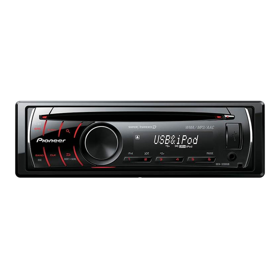
Page 10: Panel Facilities
CAUTION Use an optional Pioneer USB cable (CD-U51E) to connect the USB audio player/USB memory to the USB port. Since the USB audio player/USB memory is projected forward from the unit, it is u163 dangerous to connect directly. -
Page 11: Display Indication
http://www.xiaoyu163.com 3 7 63 1515 0 Display indication Shuffle or shuffle all function is (shuf- on while the iPod source is being fle) selected. The sound retriever function is (sound re- triever) 4 6 8 CTRL (control mode) is set to iPod iPod. -
Page 12: Connection Diagram
http://www.xiaoyu163.com 2.4 CONNECTION DIAGRAM 3 7 63 1515 0 DEH-4250SD/XNES, DEH-4250SD/XNES1 L 13942296513 u163 DEH-4250SD/XNES http://www.xiaoyu163.com... - Page 13 http://www.xiaoyu163.com 3 7 63 1515 0 L 13942296513 u163 DEH-4250SD/XNES http://www.xiaoyu163.com...
- Page 14 http://www.xiaoyu163.com 3 7 63 1515 0 DEH-4290SD/XNID Wired remote input Power amp Hard-wired remote control adaptor (sold separately) can be connected (sold separately). Front output Connect with RCA cables This product (sold separately) Power amp (sold separately) Antenna jack Rear output or subwoofer output Fuse (10 A) Yellow...
- Page 15 3 7 63 1515 0 DEH-3200UB/XNUC L 13942296513 u163 DEH-4250SD/XNES http://www.xiaoyu163.com...
- Page 16 http://www.xiaoyu163.com 3 7 63 1515 0 L 13942296513 u163 DEH-4250SD/XNES http://www.xiaoyu163.com...
-
Page 17: Basic Items For Service
http://www.xiaoyu163.com 3. BASIC ITEMS FOR SERVICE 3 7 63 1515 0 3.1 CHECK POINTS AFTER SERVICING To keep the product quality after servicing, please confirm following check points. r i f Confirm whether the customer complain has The customer complain must not be been solved. -
Page 18: Pcb Locations
CD Core Unit (S11 STD-DOUT) SD Unit (DEH-4250SD/XNES) (DEH-4250SD/XNES1) (DEH-4290SD/XNID) Tuner Amp Unit Keyboard Unit L 13942296513 A:DEH-4250SD/XNES B:DEH-4250SD/XNES1 C:DEH-4290SD/XNID D:DEH-3200UB/XNUC Unit Number CWN4805(A,B,C) Unit Number CWN5219(D) Unit Name Tuner Amp Unit Unit Number CWN4813(A,B,C) Unit Name Keyboard Unit Unit Number... -
Page 19: Jigs List
http://www.xiaoyu163.com 3.3 JIGS LIST 3 7 63 1515 0 - Jigs List Name Name Jig No. Jig No. Remarks Remarks Test Disc TCD-782 Checking the grating L.P.F. Checking the grating (Two pieces) - Grease List Name Name Grease No. Grease No. Remarks Remarks Grease... -
Page 20: Block Diagram
4. BLOCK DIAGRAM 3 7 63 1515 0 TUNER AMP UNIT :DEH-4250SD/XNES :DEH-4250SD/XNES1 JA401 :DEH-4290SD/XNID ANTENNA :DEH-3200UB/XNUC SYSTEM M COMPU IC60 PEG640 AMANT FMANT TUNL TUNPCE2 TUNPCE1 TUNPCK TUNPDO TUNPDI RESET SYS8V IC651 TUNER3V REG. ROM_VDD VDD3.3 RESET VDD3.3 S-80827CNNB-B8M VDD_3.3... - Page 21 http://www.xiaoyu163.com 3 7 63 1515 0 E.VOL IC201 PM9012A JA301 TUNL S4B-L OUTFL AUXL SYSTEM MICRO S1Q+L OUTRL Q301 COMPUTER S5B+L OUTPL IC601 PEG640A8 Q303 TUNPCE2 Q382 TUNPCE1 DATA TUNPCK TUNPDO TUNPDI MUTE Q381 VDD5V REG. Q901 VDD5 RESET Q902 DALMON IC351 PA2030A...
- Page 22 http://www.xiaoyu163.com 3 7 63 1515 0 FM/AM TUNER UNIT 10 9 8 18 19 5V → 3.3V EEPROM 5.0V AM ANT FMRF 3.3V 2.5V MIXER, IF AMP FM ANT DET, FM MPX FMRF RF adj ANT adj CF52 3.3V → 2.5V 3.3V 2.5V L 13942296513...
-
Page 23: Diagnosis
http://www.xiaoyu163.com 5. DIAGNOSIS 3 7 63 1515 0 5.1 OPERATIONAL FLOWCHART Power ON VCC1 = 3.3 V Pin 14 BSENS Pin 16 BSENS = L ASENS Pin 18 ASENS = L DSENS Pin 17 Starts communication with Grille microcomputer. L 13942296513 500 ms SWVDD <- H Pin 47... -
Page 24: Error Code List
http://www.xiaoyu163.com 5.2 ERROR CODE LIST 3 7 63 1515 0 ERROR CODES If a CD memory device is inoperable, or operation of such media is stopped by an error, the error mode is established and a cause of the error is displayed by an error code. Indication of error codes is intended to reduce the number of calls from customers and facilitate failure analysis and repair work in servicing. -
Page 25: Connector Function Description
http://www.xiaoyu163.com 5.3 CONNECTOR FUNCTION DESCRIPTION 3 7 63 1515 0 R/SW, F OUTPUT ANTENNA WIRED REMOTE CONTROL 15 13 11 9 7 5 3 1 16 14 12 10 8 6 4 2 1 FL+ 9 NC 2 FR+ 10 NC L 13942296513 3 FL- 11 NC... -
Page 26: Service Mode
For Ver.7.01, "701" is displayed Media microcomputer Version information is displayed $ $ # # $ Major version # Minor version Only /UC model (excluding DEH-3200UB/XNUC) Manufacture_ID information is displayed M I D $ $ $ $ $ $ $ $ $ Manufacture ID Display is normally updated Usual product operation is implemented to outward appearances. -
Page 27: Cd Test Mode
http://www.xiaoyu163.com 6.2 CD TEST MODE 3 7 63 1515 0 - Flow Chart NOTE When a CD-DA (regular music CD) is played in the CD test mode, its sound quality [Key] [3] + [DISP] -> Reset [CD] or [SOURCE] will be temporarily deteriorated. The CD will then repeat normal, deteriorated, Test Mode IN Source ON Contents... -
Page 28: Disassembly
http://www.xiaoyu163.com 7. DISASSEMBLY 3 7 63 1515 0 While the photograph shown is slightly different from this model in shape, the disassembly procedure is the same. - Removing the Case (not shown) 1. Remove the Case. - Removing the CD Mechanism Module (Fig.1) CD Mechanism Module Release the two latches and then remove the Panel Assy. - Page 29 http://www.xiaoyu163.com 3 7 63 1515 0 - Removing the Grille Unit 1. The seesaw button has ten hooks as shown in the figure below. Front view Oblique perspective figure 2. Disconnect eight hools shown in the figure below and pull the seesaw button. 3.
- Page 30 http://www.xiaoyu163.com 3 7 63 1515 0 How to Hold the Mechanism Unit 1. Hold the Upper and Lower Frames at the specified parts (circled with broken blue lines in the photo below). 2. You can hold the tabs of the Lower Frame (circled with broken green lines in the photo below) if you do so only while lifting the Mechanism Unit from the table.
- Page 31 http://www.xiaoyu163.com 3 7 63 1515 0 Mechanism Module: How to Set to the Quasi-Clamp State (Driven by the Motor) 1. Remove the solder from the CRG-motor lead wire (Fig. 1). 2. Push in the Disc Detection Arm while applying 4-V power to the CRG Motor (Fig. 2). (Apply 4-V power to the green lead wire.
- Page 32 http://www.xiaoyu163.com 3 7 63 1515 0 How to Remove the PU Unit 1. Set the unit to the quasi-clamp state, following the procedures described in “Mechanism Module: How to Set to the Quasi- Clamp State (Driven by the Motor).” 2. Temporarily change the engagement position of the bias spring of the feed screw (Fig. 2b). Be careful not to cut yourself on the tip of the spring.
- Page 33 http://www.xiaoyu163.com 3 7 63 1515 0 How to Remove the PU Rack 1. Remove the PU Unit, following the procedures described in “How to Remove the PU Unit.” 2. Remove the PU Rack fixing screw (Fig. 1). 3. Remove the PU Rack, by applying force in the direction of the arrow in Fig. 2. Notes: While handling the PU Unit, be careful NOT to touch the actuator block shown in Fig.
- Page 34 http://www.xiaoyu163.com 3 7 63 1515 0 How to Hold the PU 1. Be sure to hold the PU at the positions shown in “Proper handling.” NEVER hold it as shown in “Improper handling.” Proper handling Improper handling Do not touch the object lens and ACT.
-
Page 35: Each Setting And Adjustment
http://www.xiaoyu163.com 8. EACH SETTING AND ADJUSTMENT 3 7 63 1515 0 8.1 CD ADJUSTMENT 2) Test mode 1) Cautions on adjustments In this product the single voltage (3.3 V) is used for the This mode is used to adjust the CD mechanism module. regulator. -
Page 36: Checking The Grating After Changing The Pickup Unit
http://www.xiaoyu163.com 8.2 CHECKING THE GRATING AFTER CHANGING THE PICKUP UNIT 3 7 63 1515 0 Note : The grating angle of the PU unit cannot be adjusted after the PU unit is changed. The PU unit in the CD mechanism module is adjusted on the production line to match the CD mechanism module and is thus the best adjusted PU unit for the CD mechanism module. - Page 37 http://www.xiaoyu163.com 3 7 63 1515 0 Grating waveform Ech -> Xch 20 mV/div, AC Fch -> Ych 20 mV/div, AC 0 degrees 30 degrees 45 degrees 60 degrees L 13942296513 75 degrees 90 degrees u163 DEH-4250SD/XNES http://www.xiaoyu163.com...
-
Page 38: Exploded Views And Parts List
Screw adjacent to mark on the product are used for disassembly. For the applying amount of lubricants or glue, follow the instructions in this manual. (In the case of no amount instructions,apply as you think it appropriate.) 9.1 PACKING DEH-4250SD/XNES1 L 13942296513 DEH-3200UB/XNUC u163 DEH-4250SD/XNES http://www.xiaoyu163.com... - Page 39 See Contrast table (2) Service Network See Contrast table (2) Screw Assy See Contrast table (2) (2) CONTRAST TABLE DEH-4250SD/XNES, DEH-4250SD/XNES1, DEH-4290SD/XNID and DEH-3200UB/XNUC are constructed the same except for the following: Mark Description DEH-4250SD/XNES DEH-4250SD/XNES1 DEH-4290SD/XNID DEH-3200UB/XNUC Unit Box...
-
Page 40: Exterior(1)
http://www.xiaoyu163.com 9.2 EXTERIOR(1) 3 7 63 1515 0 L 13942296513 u163 DEH-4250SD/XNES http://www.xiaoyu163.com... - Page 41 Remote Control Unit CXE2758 Cover CNS7068 Lighting Conductor CNW1752 Lighting Conductor CNW1753 (2) CONTRAST TABLE DEH-4250SD/XNES, DEH-4250SD/XNES1, DEH-4290SD/XNID and DEH-3200UB/XNUC are constructed the same except for the following: Mark Description DEH-4250SD/XNES DEH-4250SD/XNES1 DEH-4290SD/XNID DEH-3200UB/XNUC Detach Grille Assy CXE2428 CXE2428 CXE2429...
-
Page 42: Exterior(2)
http://www.xiaoyu163.com 9.3 EXTERIOR(2) 3 7 63 1515 0 L 13942296513 DEH-4250SD/XNES DEH-4250SD/XNES1 DEH-4290SD/XNID u163 DEH-4250SD/XNES http://www.xiaoyu163.com... - Page 43 CXK5800 Holder CND5411 Holder CND5423 Holder YND5048 FM/AM Tuner Unit CWE2098 (2) CONTRAST TABLE DEH-4250SD/XNES, DEH-4250SD/XNES1, DEH-4290SD/XNID and DEH-3200UB/XNUC are constructed the same except for the following: Mark Description DEH-4250SD/XNES DEH-4250SD/XNES1 DEH-4290SD/XNID DEH-3200UB/XNUC Cable CDE9107 CDE9107 CDE9107 Not Used Tuner Amp Unit...
-
Page 44: Cd Mechanism Module
http://www.xiaoyu163.com 9.4 CD MECHANISM MODULE 3 7 63 1515 0 ( C ) ( C ) ( C ) ( A ) ( A ) ( D ) ( A ) ( D ) ( C ) L 13942296513 ( B ) ( D ) ( A ) ( A ) - Page 45 http://www.xiaoyu163.com CD MECHANISM MODULE SECTION PARTS LIST Mark No. Description Part No. 3 7 63 1515 0 Mark No. Description Part No. Damper CNW1198 Screw BMZ20P020FTC Screw BSZ20P040FTC CNW1726 Screw(M2 x 4) CBA1835 Motor Unit(M2)(LOAD/CRG) CXC4026 Washer CBF1038 Screw Unit CXC8894 Spring CBH3010...
-
Page 46: Schematic Diagram
"ELECTRICAL PARTS LIST". Large size SCH diagram A:DEH-4250SD/XNES E.VOL uCOM_BUS uCOM_BUS B:DEH-4250SD/XNES1 FM:-24.00 dBs AM:-24.00 dBs C:DEH-4290SD/XNID AUX: +2.20 dBs CD/USB/SD: +3.04 dBs POWER_BUS D:DEH-3200UB/XNUC POWER_BUS C211 1u/10 C209 0.22u/16 TUNL TUNL Guide page 1u/10 C201 AUXL AUXL R202 C203 2.2u/10... - Page 47 http://www.xiaoyu163.com 3 7 63 1515 0 The > mark found on some component parts indicates TUNER AMP UNIT (MAIN) the importance of the safety factor of the part. Therefore, when replacing, be sure to use parts of identical designation. RCA OUT C305 R305 R313...
- Page 48 http://www.xiaoyu163.com 3 7 63 1515 0 L 13942296513 u163 DEH-4250SD/XNES http://www.xiaoyu163.com...
- Page 49 http://www.xiaoyu163.com 3 7 63 1515 0 L 13942296513 u163 DEH-4250SD/XNES http://www.xiaoyu163.com...
- Page 50 http://www.xiaoyu163.com 3 7 63 1515 0 L 13942296513 u163 DEH-4250SD/XNES http://www.xiaoyu163.com...
- Page 51 http://www.xiaoyu163.com 3 7 63 1515 0 L 13942296513 u163 DEH-4250SD/XNES http://www.xiaoyu163.com...
-
Page 52: Tuner Amp Unit 2/2 [Media Ucom] (Guide Page)
http://www.xiaoyu163.com 10.2 TUNER AMP UNIT 2/2 [MEDIA Ucom] (GUIDE PAGE) 3 7 63 1515 0 MECHA VD Q751 7.63V 2SD2396(K) Q752 R751 R752 C2 3 1608 1608 B1 2 5 B2 VDCONT E1 1 6 C1 RT3T22M VDCONT MECHA VDSENS VDD33 CN701 VKN1192-A... - Page 53 3 7 63 1515 0 TUNER AMP UNIT (MEDIA uCOM) A:DEH-4250SD/XNES B:DEH-4250SD/XNES1 C:DEH-4290SD/XNID D:DEH-3200UB/XNUC DACMUTE DEEMPH R185 FORMAT C193 R191 DACCLK R551 C196 680p/50 C181 L501 C190 VTL1145-A 3.28V C182 1000p/10 3.3V CCG1192-A 3.3V 10u/10 DACLRCK 1.2V 1.2V DACDATA...
- Page 54 http://www.xiaoyu163.com 3 7 63 1515 0 L 13942296513 u163 DEH-4250SD/XNES http://www.xiaoyu163.com...
- Page 55 http://www.xiaoyu163.com 3 7 63 1515 0 L 13942296513 u163 DEH-4250SD/XNES http://www.xiaoyu163.com...
- Page 56 http://www.xiaoyu163.com 3 7 63 1515 0 L 13942296513 u163 DEH-4250SD/XNES http://www.xiaoyu163.com...
- Page 57 http://www.xiaoyu163.com 3 7 63 1515 0 L 13942296513 u163 DEH-4250SD/XNES http://www.xiaoyu163.com...
-
Page 58: Keyboard Unit
10.3 KEYBOARD UNIT 3 7 63 1515 0 A:DEH-4250SD/XNES B:DEH-4250SD/XNES1 C:DEH-4290SD/XNID D:DEH-3200UB/XNUC KEYBOARD UNIT R1818 CSX1120-A Phase_B Push S1811 3.29V ILMGND R1816 R1815 1.8k 3.3k Grille MICRO X1901 R1894 CSS1577-A 10.000MHz BAND S.Rtrv CSG1155-A CSG1155-A RESET S1871 S1877 DISP... - Page 59 http://www.xiaoyu163.com 3 7 63 1515 0 R1818 CSX1120-A Phase_B Phase_A ILMGND Push Enc_Com ROTARY COMMANDER JA1801 YKN5006-A R1801 5 Com JOYST(V) over~under R1802 A(UP) 0.00 0.16 S1811 AUX:+2.20 dBs B(LEFT) 0.16 0.54 LMGND DGND R1815 C(DOWN) 0.54 1.00 PUSH D(RIGHT) 1.00 1.59 1.8k...
-
Page 60: Cd Core Unit(S11Std-Dout)
http://www.xiaoyu163.com 10.4 CD CORE UNIT(S11STD-DOUT) 3 7 63 1515 0 CXX1942 PICKUP UNIT(P10.5)(SERVICE) V3R3 E:P5+P10 F:P1+P6 R106 REFO PUEN Q102 UNR511MG Q101 R109 2.2k 2SA1577(QR) R215 V+3A ATEST V+3A P5+P10 P1+P6 REFO VREF A.Vdd1 C221 A.GND1 0.1u/10 C216 1800p/50 RFAGC AGCO C220 HOLOGRAM UNIT... - Page 61 http://www.xiaoyu163.com 3 7 63 1515 0 CD CORE UNIT(S11STD-DOUT) C232 PUEN 1000p/50 SIGNAL LINE C231 R263 FOCUS SERVO LINE 1000p/50 4.7k TRACKING SERVO LINE CARRIAGE SERVO LINE R262 SPINDLE SERVO LINE 4.7k TEMP TEMP R215 TH201 Q201 TESTIN ATEST ADENA ADENA R721 R225...
-
Page 62: Sd Unit
10.5 SD UNIT 3 7 63 1515 0 A:DEH-4250SD/XNES B:DEH-4250SD/XNES1 C:DEH-4290SD/XNID D:DEH-3200UB/XNUC SD UNIT (A,B,C only) CN1202 VKN1302-A SD_DATA1 SD_DATA0 SD_CLK 3.29V SD33V SD_CMD CN781 SD_DATA3 SD_DATA2 SD_WP SD_CD L 13942296513 GND3 GND5 CD/WP GND4 GND6 CN1203 CKS6180-A u163 DEH-4250SD/XNES http://www.xiaoyu163.com... -
Page 63: D 10.6 Waveforms
http://www.xiaoyu163.com 10.6 WAVEFORMS 3 7 63 1515 0 - Waveforms Note : 1. The encircled numbers denote measuring points in the circuit diagram. 2. Reference voltage REFO1(1.65 V) 1DSCSNS 1DSCSNS 1DSCSNS 5 V/div 500 ms/div 5 V/div 500 ms/div 5 V/div 500 ms/div 28SNS 5CLCONT... - Page 64 http://www.xiaoyu163.com 3 7 63 1515 0 10 μs/div fRFAGC fRFAGC gLRCK 1 V/div 2 ms/div 1 V/div 200 ms/div 2 V/div hBCLK 500 mV/div 1 V/div 2 V/div 9TIN 8CIN iDATA 500 mV/div 500 mV/div 2 V/div 7SIN 2 V/div 32 Tracks Jump waveform Search operation(Outter to Inner) Digital Out waveform...
- Page 65 http://www.xiaoyu163.com 3 7 63 1515 0 L 13942296513 u163 DEH-4250SD/XNES http://www.xiaoyu163.com...
-
Page 66: Pcb Connection Diagram
http://www.xiaoyu163.com 11. PCB CONNECTION DIAGRAM 11.1 TUNER AMP UNIT 3 7 63 1515 0 NOTE FOR PCB DIAGRAMS TUNER AMP UNIT 1.The parts mounted on this PCB include all necessary parts for several destination. For further information for WIRED REMOTE respective destinations, be sure JA661 to check with the schematic dia-... - Page 67 http://www.xiaoyu163.com 3 7 63 1515 0 SIDE A CORD ASSY L981 JA981 FUSE IC351 C369 C368 C365 D941 D981 R823 L951 C941 Q931 D982 D931 R834 R932 C932 C921 Q363 R926 C217 Q821 R833 ANTENNA C951 R925 C361 C218 D922 Q832 JA401 D942...
- Page 68 http://www.xiaoyu163.com 3 7 63 1515 0 TUNER AMP UNIT C366 C362 D431 D432 C433 IC431 C431 C432 Q831 ZNR401 L404 R602 L 13942296513 C788 R525 R514 R526 R515 R527 C547 R532 R533 C551 R534 C535 C550 C536 R560 R535 R531 C802 R809 C801...
- Page 69 http://www.xiaoyu163.com 3 7 63 1515 0 SIDE B C362 R382 R381 Q381 R384 D382 D381 C216 C213 Q831 C222 C221 C219 C220 C212 C211 R169 R168 R166 R164 D901 R165 R167 C167 D582 L 13942296513 C581 IC901 C907 C788 C906 C905 D903 u163...
-
Page 70: Keyboard Unit
http://www.xiaoyu163.com 11.2 KEYBOARD UNIT 3 7 63 1515 0 KEYBOARD UNIT SIDE A D1866 D1860 D1844 C1842 C1843 D1843 D1859 D1858 D1842 C1844 D1856 D1840 L 13942296513 C1840 C1839 D1839 D1855 u163 DEH-4250SD/XNES http://www.xiaoyu163.com... - Page 71 http://www.xiaoyu163.com 3 7 63 1515 0 KEYBOARD UNIT SIDE B L 13942296513 u163 DEH-4250SD/XNES http://www.xiaoyu163.com...
-
Page 72: Cd Core Unit(S11Std-Dout)
http://www.xiaoyu163.com 11.3 CD CORE UNIT(S11STD-DOUT) 3 7 63 1515 0 CD CORE UNIT (S11STD-DOUT) SIDE A PICKUP UNIT(P10.5)(SERVICE) CN101 LOADING/CARRIAGE S901 TH201 HOME MOTOR C102 REFO1 SPINDLE D101 C216 MOTOR C235 CN702 R216 C224 R229 R246 C225 C223 C222 C219 C221 R214 C213... - Page 73 http://www.xiaoyu163.com 3 7 63 1515 0 CD CORE UNIT (S11STD-DOUT) SIDE B R102 C101 R103 R101 C111 C110 C104 Q101 R108 Q102 R109 R106 C239 C220 C236 C229 L 13942296513 C205 C301 C308 Q201 C206 R245 R240 R296 R254 R253 C231 C232 S905...
-
Page 74: Sd Unit
http://www.xiaoyu163.com 11.4 SD UNIT 3 7 63 1515 0 SD UNIT SIDE A CN1202 CN781 CN1203 L 13942296513 SD UNIT SIDE B u163 DEH-4250SD/XNES http://www.xiaoyu163.com... -
Page 75: Electrical Parts List
BH12PB3WHFV IC 591 (A,102,23) IC 341S2162 C:DEH-4290SD/XNID IC 601 (A,128,96) IC PEG640A8 IC 651 (A,119,108) IC S-80827CNNB-B8M D:DEH-3200UB/XNUC IC 901 (B,24,70) Regulator IC S-1132B33-U5 Unit Number : CWN4805(A,B,C) IC 911 (A,7,122) IC NJM2388F84 Q 301 (A,14,126) Transistor UMH3N Unit Number : CWN5219(D) - Page 76 http://www.xiaoyu163.com Circuit Symbol and No. Part No. Circuit Symbol and No. Part No. D 801 (A,116,14) Diode DZ2S068C R 192 (A,92,104) RS1/16SS821J 3 7 63 1515 0 D 802 (A,119,14) Diode DZ2S068C R 201 (A,69,124) RAB4CQ102J D 803 (A,122,13) Diode DZ2S068C R 202 (A,80,105)
- Page 77 http://www.xiaoyu163.com Circuit Symbol and No. Part No. Circuit Symbol and No. Part No. R 577 (A,142,33) RAB4CQ221J 3 7 63 1515 0 R 578 (A,138,35) RAB4CQ221J R 784 (A,100,60) (A,B,C) RS1/16SS221J R 591 (A,111,24) RS1/16SS472J R 785 (A,100,59) (A,B,C) RS1/16SS221J R 592 (A,108,28) RS1/16SS101J...
- Page 78 http://www.xiaoyu163.com Circuit Symbol and No. Part No. Circuit Symbol and No. Part No. C 190 (A,119,74) CKSSYB102K10 C 519 (A,127,65) CKSSYB104K10 3 7 63 1515 0 C 191 (A,89,103) CCSRCH182J50 C 520 (A,124,65) CKSSYB104K10 C 192 (A,90,103) CCSRCH182J50 C 521 (A,124,66) CKSSYB104K10 C 196...
- Page 79 http://www.xiaoyu163.com Circuit Symbol and No. Part No. Circuit Symbol and No. Part No. C 901 (A,15,63) CEAT102M16 R 1811 (B,68,16) RS1/10SR102J 3 7 63 1515 0 R 1812 (B,47,12) RS1/10SR102J C 902 (A,14,79) CKSSYB103K10 R 1813 (B,49,13) RS1/10SR103J C 904 (A,16,72) 10 uF CCG1192 C 905...
- Page 80 http://www.xiaoyu163.com Circuit Symbol and No. Part No. Circuit Symbol and No. Part No. S 1880 (A,115,7) Push Switch CSG1155 3 7 63 1515 0 C 1921 (A,89,25) CKSRYB105K10 S 1881 (A,120,7) Push Switch CSG1155 C 1922 (A,89,23) CKSRYB105K10 S 1882 (A,149,42) Push Switch CSG1155 C 1923...
- Page 81 http://www.xiaoyu163.com Circuit Symbol and No. Part No. Circuit Symbol and No. Part No. R 232 (A,19,21) RS1/16SS0R0J 3 7 63 1515 0 R 1910 (B,75,24) RS1/10SR473J R 235 (A,45,32) RS1/16SS103J R 1922 (A,89,21) RS1/10SR5102D R 236 (A,46,32) RS1/16SS103J R 1924 (A,107,25) RAB4C101J R 1925...
- Page 82 http://www.xiaoyu163.com Circuit Symbol and No. Part No. C 299 (A,17,33) CKSSYB104K10 3 7 63 1515 0 C 304 (A,60,35) CKSSYB472K25 C 305 (A,58,35) CKSSYB223K16 C 306 (A,68,20) CKSRYB105K10 C 710 (B,43,10) CKSSYB102K50 Unit Number : CWN4816(A,B,C) Unit Name : SD Unit MISCELLANEOUS CN1202 (A,33,43)