Table of Contents
Advertisement
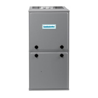
35" Tall, High Efficiency Condensing Gas Furnace
DANGER, WARNING, CAUTION, and NOTE
The
signal
words
CAUTION, and NOTE are used to identify levels of
hazard seriousness. The signal word DANGER is
only used on product labels to signify an immediate
hazard. The signal words WARNING, CAUTION,
and NOTE will be used on product labels and
throughout this manual and other manual that may
apply to the product.
DANGER − Immediate hazards which will result in
severe personal injury or death.
WARNING − Hazards or unsafe practices which
could result in severe personal injury or death.
CAUTION − Hazards or unsafe practices which
may result in minor personal injury or product or
property damage.
NOTE − Used to highlight suggestions which will
result in enhanced installation, reliability, or
operation.
TABLE OF CONTENTS
. . . . . . . . . . . . . . . . . . . . . . . . . . . . . . . . . . . . . .
. . . . . . . . . . . . . . . . . . . . . . . . . . . . . . . . . . . . . . . . .
. . . . . . . . . . . . . . . . . . . . . . . . . . . . . . . . . . . . . . . . . . . . .
. . . . . . . . . . . . . . . . . . . . . . . . . . . . . . . . . . . .
. . . . . . . . . . . . . . . . . . . . . . . . . . . . . . . . . . . . . . . . .
. . . . . . . . . . . . . . . . . . . . . . . . . . . . . . . . . . . . . . .
Printed in U.S.A.
SERVICE AND TECHNICAL
SUPPORT MANUAL
Two−Stage, ECM Blower Motor
Save this manual for future reference.
Safety Labeling and Signal Words
DANGER,
WARNING,
. . . . . . . . . . .
. . . . . . . . . . . . . . . . . . . . . . . . . . .
. . . . . . . . . . . . . . . . .
. . . . . . . . . . . . . . . . . . . . . . . . . . . .
. . . . . . . . . . . . . .
. . . . . . . . . . . . . . . . . . . . . . . . . . . . .
. . . . . . . . . . . . . . . . . . . .
. . . . . . . . . . . . . . .
. . . . . . . . . . . . . . . . . . . . . . . . . . . . .
. . . . . . . . . . . . .
. . . . . . . . . . . . . . . . . . .
. . . . . . . . . . . . . .
. . . . . . . . . . . .
. . . . . . . . . . . . . . .
. . . . . . . . . . . . . . . . . . . . . .
. . . .
. . . . . . . . . . . . . .
. . . . . . . . . . . . . . . . . . . . . . . . . .
. . . . . . . . . . . . . . . . . . . . . . . . . . . . .
. . . . . . . . . . . . .
. . . . . . . . . . . . . . . . . . . . . . . . . . . . .
(F/G)9MXT
Signal Words in Manuals
The signal word WARNING is used throughout
this manual in the following manner:
WARNING
!
The signal word CAUTION is used throughout
this manual in the following manner:
CAUTION
!
Signal Words on Product Labeling
Signal words are used in combination with
colors and/or pictures or product labels.
Safety−alert symbol
When you see this symbol on the unit and in
instructions or manuals, be alert to the
potential for personal injury.
4
4
4
4
5
10
11
11
11
11
12
12
13
13
13
15
15
17
18
18
19
19
21
22
25
29
30
MODELS
(F/G)9MXT0401410A
(F/G)9MXT0401712A
(F/G)9MXT0601412A
(F/G)9MXT0601714A
(F/G)9MXT0801716A
(F/G)9MXT0802120A
(F/G)9MXT1002120A
(F/G)9MXT1202422A
Use of the AHRI Certified TM Mark indicates a
manufacturer's participation in the program.
For verification of certification for individual
products, go to www.ahridirectory.org .
440 04 4321 08
11/25/13
Advertisement
Table of Contents

Related Manuals for International comfort products F9MXT0401410A


Summary of Contents for International comfort products F9MXT0401410A
-
Page 1: Table Of Contents
SERVICE AND TECHNICAL SUPPORT MANUAL Two−Stage, ECM Blower Motor 35” Tall, High Efficiency Condensing Gas Furnace (F/G)9MXT Save this manual for future reference. Safety Labeling and Signal Words DANGER, WARNING, CAUTION, and NOTE Signal Words in Manuals signal words DANGER, WARNING, The signal word WARNING is used throughout CAUTION, and NOTE are used to identify levels of... -
Page 2: Safety Considerations
SAFETY CONSIDERATIONS WARNING Improper ins t allation, adjus t ment, alteration, serv ic e, maintenance, or use can cause explosion, fire, electrical shock, PERSONAL INJURY, AND/OR PROPERTY or other conditions which may cause death, personal injury, or DAMAGE HAZARD property damage. Consult a qualified installer, service agency, Failure to carefully read and follow this warning could or your distributor or branch for information or assistance. - Page 3 SERVICE AND TECHNICAL MANUAL Gas Furnace: (F/G)9MXT START−UP CHECK SHEET For PSC Models (F/G)9MXT (This sheet is optional. Keep for future reference.) Date of Start−Up: Calculated Input (BTU) Rate: (See Checks and Adjustments Section). Dealer Name: Heating Check Address: Measured Line Pressure During High Heat: City, State(Province), Zip or Postal Code: Measured Manifold Pressure: High Heat...
-
Page 4: Start−Up, Adjustment, And Safety Check
SERVICE AND TECHNICAL SUPPORT MANUAL Gas Furnace: (F/G)9MXT START−UP, ADJUSTMENT, AND SAFETY factory−shipped OFF position. See Figure 7 and Figure 15 for setup switch information. CHECK If a two−stage heating thermostat is to be used, move setup switch SW−1 (TT) to ON position before starting furnace. This NOTICE overrides built−in control process for selecting high and low heat and allows the two−stage thermostat to select gas heating... -
Page 5: Purge Gas Lines
SERVICE AND TECHNICAL SUPPORT MANUAL Gas Furnace: (F/G)9MXT Purge Gas Lines NOTICE If not previously done, purge the lines after all connections have been made and check for leaks. The NATURAL GAS manifold pressure adjustments in Table 3 WARNING compensate for BOTH altitude AND gas heating value. DO NOT apply an additional de−rate factor to the pressures shown in Table 3. - Page 6 SERVICE AND TECHNICAL SUPPORT MANUAL Gas Furnace: (F/G)9MXT Adjust Manifold Pressure 5. Check and verify burner orifice size in furnace. NEVER ASSUME ORIFICE SIZE. ALWAYS CHECK AND 1. Adjust manifold pressure to obtain low fire input rate. VERIFY. (See Figure 3) a.
- Page 7 SERVICE AND TECHNICAL SUPPORT MANUAL Gas Furnace: (F/G)9MXT or decrease manifold pressure to decrease input. NOTICE Repeat steps b through e of Step 1 until correct low−heat input is achieved. Re−install low heat regulator seal cap on gas valve. DO NOT set high−heat manifold pressure less than 3.2−in. w.c. (797 Pa) or more than 3.8 in.
- Page 8 SERVICE AND TECHNICAL SUPPORT MANUAL Gas Furnace: (F/G)9MXT Table 2 Gas Rate (CU ft./hr) SECONDS G SIZE OF TEST DIAL SECONDS SIZE OF TEST DIAL FOR 1 REVOLUTION FOR 1 REVOLUTION 1 Cu Ft. 2 Cu Ft. 5 Cu Ft. 1 Cu Ft.
- Page 9 SERVICE AND TECHNICAL SUPPORT MANUAL Gas Furnace: (F/G)9MXT Table 3 Orifice Size and Manifold Pressure (in. w.c.) for Gas Input Rate TWO-STAGE FURNACE (TABULATED DATA BASED ON 20,000 BTUH HIGH-HEAT / 13,000 BTUH LOW-HEAT PER BURNER, DERATED 2%/1000 FT (305M) ABOVE SEA LEVEL) ALTITUDE RANGE HEAT VALUE...
-
Page 10: Adjust Temperature Rise
SERVICE AND TECHNICAL SUPPORT MANUAL Gas Furnace: (F/G)9MXT Table 3 (Cont.) Orifice Size and Manifold Pressure (in. w.c.) for Gas Input Rate TWO-STAGE FURNACE (TABULATED DATA BASED ON 20,000 BTUH HIGH-HEAT / 13,000 BTUH LOW-HEAT PER BURNER, DERATED 2%/1000 FT (305M) ABOVE SEA LEVEL) ALTITUDE RANGE HEAT VALUE... -
Page 11: Adjust Blower Off Delay (Heat Mode)
SERVICE AND TECHNICAL SUPPORT MANUAL Gas Furnace: (F/G)9MXT Adjust Continuous Fan Airflow Table 4 Blower Speed Taps The Continuous Fan airflow can be set from the remaining FACTORY COLOR SPEED blower speed taps. Refer to the Air Delivery Tables in these ATTACHED TO: instructions. -
Page 12: Check Safety Controls
SERVICE AND TECHNICAL SUPPORT MANUAL Gas Furnace: (F/G)9MXT Table 6 AIR DELIVERY - CFM (with filter EXTERNAL STATIC PRESSURE (in. w.c.) UNIT RETURN-AIR SPEED SIZE CONNECTION TAPS Gray 1120 1080 1030 Yellow 0401410 SIDE/BOTTOM Blue Orange Gray 1255 1220 1175 1130 1085 1040... -
Page 13: Checklist
SERVICE AND TECHNICAL SUPPORT MANUAL Gas Furnace: (F/G)9MXT igniter glows when inducer motor is disconnected, WARNING shut down furnace immediately. e. Determine reason pressure switch did not function ELECTRICAL SHOCK, FIRE OR EXPLOSION properly and correct condition. HAZARD f. Turn off 115−V power to furnace. Failure to follow this warning could result in personal g. -
Page 14: Troubleshooting
SERVICE AND TECHNICAL SUPPORT MANUAL Gas Furnace: (F/G)9MXT wiring during installation, service, or maintenance will cause WARNING this fuse to blow. If fuse replacement is required, use ONLY a 3−amp. fuse. The control LED display will be off when fuse ELECTRICAL SHOCK HAZARD needs to be replaced. -
Page 15: Cleaning And/Or Replacing Air Filter
SERVICE AND TECHNICAL SUPPORT MANUAL Gas Furnace: (F/G)9MXT Caution must be taken when manually closing this switch for WARNING service purposes. WARNING ELECTRICAL SHOCK AND FIRE HAZARD Failure to follow this warning could result in personal ELECTRICAL SHOCK HAZARD injury, death, and/or property damage. Failure to follow this warning could result in personal Turn off the gas and electrical supplies to the furnace injury, or death. -
Page 16: Blower Motor And Wheel Maintenance
SERVICE AND TECHNICAL SUPPORT MANUAL Gas Furnace: (F/G)9MXT e. Remove the couplings from the pipe adapters and set WARNING aside. f. After servicing the blower, reverse steps a through e. ELECTRICAL SHOCK, FIRE OR EXPLOSION g. Tighten all clamps 15 lb−in. HAZARD See Figure 8 for steps 5 through 14. -
Page 17: Cleaning Burners And Flame Sensor
SERVICE AND TECHNICAL SUPPORT MANUAL Gas Furnace: (F/G)9MXT WARNING Figure 8 Blower Assembly MOTOR SHAFT FLAT ELECTRICAL OPERATION HAZARD Failure to follow this warning could result in personal injury or death. Blower door switch opens 115−V power to control. No component operation can occur unless switch is closed. - Page 18 SERVICE AND TECHNICAL SUPPORT MANUAL Gas Furnace: (F/G)9MXT 6. Remove individual wires from terminals on gas valve. 6. Attach the green/yellow wire and ground terminal to one of the manifold mounting screws. 7. Disconnect Hot Surface Igniter (HSI) wires from HSI. 7.
-
Page 19: Servicing Hot Surface Igniter
SERVICE AND TECHNICAL SUPPORT MANUAL Gas Furnace: (F/G)9MXT 16. Turn power on at external disconnect, fuse or circuit 6. Flush inside of collector box with water until discharge breaker. water from condensate trap is clean and runs freely. 17. Run the furnace through two complete heating cycles to 7. -
Page 20: Cleaning Heat Exchangers
SERVICE AND TECHNICAL SUPPORT MANUAL Gas Furnace: (F/G)9MXT 11. Run the furnace through two complete heating cycles to Figure 12 Cleaning Heat Exchanger Cell check for proper operation 12. Install control door when complete. Checking Heat Pad Operation (If Applicable) In applications where the ambient temperature around the furnace is 32_F (0_C) or lower, freeze protection measures are required. - Page 21 SERVICE AND TECHNICAL SUPPORT MANUAL Gas Furnace: (F/G)9MXT Secondary Heat Exchangers 1. Obtain propylene glycol (RV/swimming pool antifreeze or equivalent). The condensing side (inside) of the secondary heat exchanger 2. Turn off gas and electrical supplies to your furnace. CANNOT be serviced or inspected without complete removal of the heat exchanger assembly.
-
Page 22: Service Label
SERVICE AND TECHNICAL SUPPORT MANUAL Gas Furnace: (F/G)9MXT Figure 14 Service Label 338313−2 Rev. I 440 04 4321 08 Specifications subject to change without notice. -
Page 23: Wiring Diagram
SERVICE AND TECHNICAL SUPPORT MANUAL Gas Furnace: (F/G)9MXT Figure 15 Wiring Diagram 338313−2 Rev. I 440 04 4321 08 Specifications subject to change without notice. - Page 24 SERVICE AND TECHNICAL SUPPORT MANUAL Gas Furnace: (F/G)9MXT Figure 16 Troubleshooting Guide − Flow Chart 440 04 4321 08 Specifications subject to change without notice.
- Page 25 SERVICE AND TECHNICAL SUPPORT MANUAL Gas Furnace: (F/G)9MXT Figure 16 (CONT.) Troubleshooting Guide − Flow Chart 440 04 4321 08 Specifications subject to change without notice.
-
Page 26: Sequence Of Operation
SERVICE AND TECHNICAL SUPPORT MANUAL Gas Furnace: (F/G)9MXT Sequence of Operation NOTE: Furnace control must be grounded for proper operation c. Trial−for−Ignition Sequence−When igniter or control will lockout. Control is grounded through green wire warm−up period is completed the main gas valve relay connected to gas valve and burner bracket screw. - Page 27 SERVICE AND TECHNICAL SUPPORT MANUAL Gas Furnace: (F/G)9MXT NOTE: In this mode the TT switch (SW1−1) must be ON to thermostat connections) The dehumidification output, H select the two−stage thermostat mode in response to closing on the humidity sensing thermostat should be connected the thermostat R−to−W1 circuit.
- Page 28 SERVICE AND TECHNICAL SUPPORT MANUAL Gas Furnace: (F/G)9MXT the prepurge period, then shut off for 24 seconds then Two−Stage Furnace with Two−Stage Air Figure 18 come back on at LO HEAT speed. When the W/W1 input Conditioner signal disappears, the furnace control begins a normal inducer post−purge period and the blower remains running HEAT...
- Page 29 SERVICE AND TECHNICAL SUPPORT MANUAL Gas Furnace: (F/G)9MXT Two−Stage Furnace with Two−Stage HP with Two−Stage Furnace, Humidifier, Figure 20 Figure 22 Heat Pump (Dual Fuel) and Dehumidification NOTE 9 Figure 23 Two−Stage Furnace and Humidifier Only AC with Two−Stage Furnace, Humidifier, Figure 21 and Dehumidification For Figure 17 −...
-
Page 30: Parts Replacement Information Guide
TO OBTAIN INFORMATION ON PARTS: Consult your installing dealer or the classified section of your local telephone directory under the “Heating Equipment“ or “Air Conditioning Contractors and Systems” headings for dealer listing by brand name. International Comfort Products Consumer Relations Department P.O. -
Page 31: Product Nomenclature
16 = 1600 CFM (max) 20 = 2000 CFM (max) 22 = 2200 CFM (max) COOLING AIRFLOW SALES (MAJOR) REVISION DIGIT ENGINEERING (MINOR) REVISION DIGIT 440 04 4321 08 Specifications subject to change without notice. Copyright 2013 International Comfort Products...