Table of Contents
Advertisement
SPLIT-TYPE AIR CONDITIONERS
OUTDOOR UNIT
SERVICE MANUAL
Models
MUZ-D30NA / -
MUZ-D36NA / -
MUY-D30NA / -
MUY-D36NA / -
NOTE:
RoHS compliant products have <G> mark on the spec name plate.
HFC
utilized
R410A
/ -
/ -
1
U1
U2
/ -
/ -
1
U1
U2
1
1
CONTENTS
1. TECHNICAL CHANGES ··································· 3
2. PART NAMES AND FUNCTIONS ····················· 3
3. SPECIFICATION ················································ 4
4. OUTLINES AND DIMENSIONS ························ 6
5. WIRING DIAGRAM ············································ 7
6. REFRIGERANT SYSTEM DIAGRAM ··············11
7. DATA ································································ 13
8. ACTUATOR CONTROL ··································· 20
9. SERVICE FUNCTIONS ··································· 21
10. TROUBLESHOOTING ····································· 22
11. DISASSEMBLY INSTRUCTIONS ···················· 41
PARTS CATALOG (OBB502)
• Errors in TROUBLESHOOTING have been
corrected.
Please void OBH502 REVISED EDITION-B.
No. OBH502
REVISED EDITION-C
Indoor unit service manual
MSZ-D•NA Series (OBH501)
MSY-D•NA Series (OBH501)
TM
Advertisement
Table of Contents
Troubleshooting

Related Manuals for Mitsubishi MUZ-D30NA


Summary of Contents for Mitsubishi MUZ-D30NA
-
Page 1: Table Of Contents
Please void OBH502 REVISED EDITION-B. OUTDOOR UNIT No. OBH502 SERVICE MANUAL REVISED EDITION-C utilized R410A Models MUZ-D30NA / - MUZ-D36NA / - MUY-D30NA / - MUY-D36NA / - Indoor unit service manual MSZ-D•NA Series (OBH501) MSY-D•NA Series (OBH501) CONTENTS 1. TECHNICAL CHANGES ··································· 3 2. -
Page 2: Revision C
Use the specifi ed refrigerant only Never use any refrigerant other than that specified. Doing so may cause a burst, an explosion, or fire when the unit is being used, serviced, or disposed of. Correct refrigerant is specified in the manuals and on the spec labels provided with our products. We will not be held responsible for mechanical failure, system malfunction, unit breakdown or accidents caused by failure to follow the instructions. -
Page 3: Technical Changes
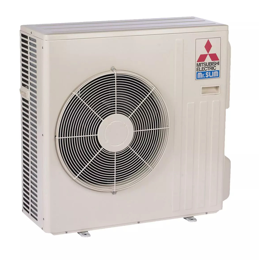
→ MUZ-D36NA- MUY-D30NA → MUY-D30NA- MUY-D36NA → MUY-D36NA- 1. Wiring diagram has been changed. 2. Fan motor has been changed. PART NAMES AND FUNCTIONS MUZ-D30NA MUZ-D36NA MUY-D30NA MUY-D36NA Air inlet (back and side) Piping Drain hose Air outlet Drain outlet... -
Page 4: Specification
8.2 (6.7) — 8.2 (6.7) — Heating 1 2.84 — 2.69 — Outdoor unit model MUZ-D30NA MUY-D30NA MUZ-D36NA MUY-D36NA Power supply V , phase , Hz 208/230 , 1 , 60 Max. fuse size (time delay) Min. circuit ampacity Fan motor F.L.A... - Page 5 Test condition 3, 4 Indoor air condition (°F) Outdoor air condition (°F) Mode Test Dry bulb Wet bulb Dry bulb Wet bulb "A" Cooling Steady State (75) at rated compressor Speed "B-2" Cooling Steady State (65) at rated compressor Speed SEER "B-1"...
-
Page 6: Outlines And Dimensions
OUTLINES AND DIMENSIONS MUZ-D30NA MUZ-D36NA MUY-D30NA MUY-D36NA Unit: inch Open as a rule REQUIRED SPACE 20 inch or more if the front and both sides are open 4 inch or more / 8 inch or more if there are obstacles... -
Page 7: Wiring Diagram
WIRING DIAGRAM MUZ-D30NA MUZ-D30NA- MUZ-D36NA MUZ-D36NA-... - Page 8 MUZ-D30NA- MUZ-D30NA- MUZ-D36NA- MUZ-D36NA-...
- Page 9 MUY-D30NA MUY-D36NA...
- Page 10 MUY-D30NA- MUY-D36NA-...
-
Page 11: Refrigerant System Diagram
REFRIGERANT SYSTEM DIAGRAM MUZ-D30NA MUZ-D36NA Unit: inch Strainer Capillary tube separator #100 O.D. 0.071 x I.D. 0.024 x 39-3/8 Refrigerant pipe ( 1.8 x 0.6 x 1,000) 4-way valve (with heat insulator) Service Stop valve port (with service port) Outdoor... - Page 12 MAX. REFRIGERANT PIPING LENGTH and MAX. HEIGHT DIFFERENCE Refrigerant piping: ft. Piping size O.D: in. Model Max. Length Max. Height difference Liquid MUZ-D30NA MUZ-D36NA MUY-D30NA MUY-D36NA Indoor unit Max. Height difference Max. Length Outdoor unit ADDITIONAL REFRIGERANT CHARGE (R410A: oz.) Refrigerant piping exceeding 25 ft.
-
Page 13: Data
DATA MUZ-D30NA MUZ-D36NA MUY-D30NA MUY-D36NA 7-1. PERFORMANCE DATA 1) COOLING CAPACITY Indoor air Outdoor intake air DB temperature (˚F) Model IWB (˚F) 37.6 19.1 3.43 35.2 17.8 3.75 33.0 16.7 4.04 30.7 15.6 4.25 28.2 14.3 4.43 MUZ-D30NA 35.6 22.8 3.23... -
Page 14: Performance Curve
7-2. PERFORMANCE CURVE Cooling MUZ-D36NA MUY-D30NA MUZ-D30NA SHF at rating condition = 0.64 SHF at rating condition = 0.62 SHF at rating condition = 0.64 Airflow = 763 CFM Airflow = 763 CFM Airflow = 763 CFM Outdoor intake air DB temperature (°F) Outdoor intake air DB temperature (°F) - Page 15 7-3. CONDENSING PRESSURE Cooling Data is based on the condition of indoor humidity 50%. Air flow should be set to High speed. MUZ-D30NA (PSIG) (PSIG) 68 70 105(°F) 68 70 105(°F) Outdoor ambient temperature Outdoor ambient temperature MUZ-D36NA (PSIG) (PSIG) 68 70 105(°F)
- Page 16 Outdoor ambient temperature Heating Data is based on the condition of outdoor humidity 75%. Air flow should be set to High speed. Data is for heating operation without any frost. MUZ-D30NA (PSIG) (PSIG) 58Hz 58Hz 20 25 30 35 40 45 50 55 60 65 70 65 70(°F)
- Page 17 Indoor unit MSZ-D30NA MSZ-D36NA MSY-D30NA MSY-D36NA Power supply phase, 208/230 , 1 , 60 Input 0.058 Fan motor current 0.45/0.42 Outdoor unit MUZ-D30NA MUZ-D36NA MUY-D30NA MUY-D36NA Power supply phase, 208/230 , 1 , 60 Input 3.792 3.302 4.082/4.302 3.782 3.322 4.152/4.182...
- Page 18 7-5. CAPACITY AND INPUT CORRECTION BY INVERTER OUTPUT FREQUENCY MUZ-D30NA Correction of Cooling capacity Correction of Cooling total input Correction of Heating total input Correction of Heating capacity (Hz) (Hz) (Hz) (Hz) The operational frequency of compressor The operational frequency of compressor...
- Page 19 7-6. TEST RUN OPERATION (How to operate fixed-frequency operation) 1. Press EMERGENCY OPERATION switch to COOL or HEAT mode (COOL: Press once, HEAT: Press twice). 2. Test run operation starts and continues to operate for 30 minutes. 3. Compressor operates at rated frequency in COOL mode or 58 Hz in HEAT mode. 4.
-
Page 20: Actuator Control
ACTUATOR CONTROL MUZ-D30NA MUZ-D36NA MUY-D30NA MUY-D36NA 8-1. OUTDOOR FAN MOTOR CONTROL The fan motor turns ON/OFF, interlocking with the compressor. [ON] The fan motor turns ON 5 seconds before the compressor starts up. [OFF] The fan motor turns OFF 15 seconds after the compressor has stopped running. -
Page 21: Service Functions
SERVICE FUNCTIONS MUZ-D30NA MUZ-D36NA MUY-D30NA MUY-D36NA 9-1. PRE-HEAT CONTROL If moisture gets into the refrigerant cycle, or when refrigerant is liquefi ed and col- lected in the compressor, it may interfere the start-up of the compressor. To improve start-up condition, the compressor is energized even while it is not operating. -
Page 22: Troubleshooting
TROUBLESHOOTING MUZ-D30NA MUZ-D36NA MUY-D30NA MUY-D36NA 10-1. CAUTIONS ON TROUBLESHOOTING 1. Before troubleshooting, check the following 1) Check the power supply voltage. 2) Check the indoor/outdoor connecting wire for miswiring. 2. Take care of the following during servicing 1) Before servicing the air conditioner, be sure to turn OFF the main unit first with the remote controller, and after con- firming the horizontal vane is closed, turn off the breaker and/or disconnect the power plug. -
Page 23: Failure Mode Recall Function
10-2. FAILURE MODE RECALL FUNCTION Outline of the function This air conditioner can memorize the abnormal condition which has occurred once. Even though LED indication listed on the troubleshooting check table (10-3.) disappears, the memorized failure details can be recalled. This mode is very useful when the unit needs to be repaired for the abnormality which does not recur. - Page 24 2. Flow chart of the detailed outdoor unit failure mode recall function Operational procedure The outdoor unit might be abnormal. Confi rm if outdoor unit is abnormal according to the following procedures. Confi rm that the remote controller is in the failure mode recall function. With the remote controller headed towards the indoor unit, press TOO 1.
- Page 25 3. Outdoor unit failure mode table MUZ-D30NA MUZ-D36NA MUY-D30NA MUY-D36NA LED indication (Outdoor P.C. The left lamp of OPERA- Indoor/outdoor Abnormal point board) TION INDICATOR lamp Condition Remedy unit failure mode (Failure mode / protection) (Indoor unit) recall function LED 1...
- Page 26 LED indication (Out- The left lamp of OPERA- Indoor/outdoor door P.C. board) Abnormal point TION INDICATOR lamp Condition Remedy unit failure mode (Failure mode / protection) (Indoor unit) recall function LED 1 LED 2 • Check the voltage of A failure is detected in the operation of the converter dur- Converter 5 times Goes out...
-
Page 27: Troubleshooting Check Table
10-3. TROUBLESHOOTING CHECK TABLE MUZ-D30NA MUZ-D36NA MUY-D30NA MUY-D36NA Indication Symptom Abnormal point / Condition Condition Remedy LED1 LED2 (Red) (Yellow) • Check the connection of the compressor connect- IPM protection stop or lock protection stop is continuously ing wire. performed three times within 1 minute after the compressor •... - Page 28 Indication Symptom Abnormal point / Condition Condition Remedy LED1 LED2 (Red) (Yellow) Primary current protection The input current exceeds 15 A. • These symptoms do not mean any abnormality of Once Lighting Secondary current protection The current of the compressor exceeds 15 A. the product, but check the following points.
- Page 29 10-4. TROUBLE CRITERION OF MAIN PARTS MUZ-D30NA MUZ-D36NA MUY-D30NA MUY-D36NA Part name Check method and criterion Figure Defrost thermistor (RT61) (MUZ) Ambient temperature thermistor (RT65) Measure the resistance with a tester. Outdoor heat ex- Refer to 10-6. “Test point diagram and voltage”, 1. “Outdoor electron- changer temperature ic control P.C.
-
Page 30: Troubleshooting Flow
10-5. TROUBLESHOOTING FLOW A How to check inverter/compressor Disconnect the terminal of the compressor. 3 minutes after turn- ing on the power supply, start EMERGENCY OPERATION. •After the outdoor fan starts running, wait for 1 minute or more before measur- ing the voltage. - Page 31 B Check of outdoor thermistors Disconnect the connector of thermistor in the outdoor P.C. board (see below table), and measure the resistance of thermistor. Replace the thermistor except RT64. Is the thermistor normal? (Refer to 10-6.1.) When RT64 is abnormal, replace the outdoor power board.
- Page 32 C Check of R.V. coil MUZ-D30/36 • Heating operation does not work. Disconnect the lead wire leading to the compressor. 3 minutes after turning on the power supply, start EMERGENCY OPERATION in HEAT mode. Is there voltage of 208/230 VAC between pin1 Turn off power supply of indoor and outdoor unit, and discon- and pin 2 at connector CN912? nect the connector CN781 in the outdoor electronic control P.C.
- Page 33 D Check of outdoor fan motor Check the connection between the connector CN931 and CN932. Is the resistance between each ter- minal of outdoor fan motor normal? (Refer to 10-4.) Disconnect CN932 from outdoor electronic control P.C. board, and turn on the power supply. Rotate the outdoor fan motor manually and measure the voltage of CN931.
- Page 34 F Check of compressor start failure Confi rm that 1~4 is normal. •Electrical circuit check Contact of lead wire leading to compressor Output voltage of the outdoor electronic control P.C. board and balance of them (See 10-5. ) Direct current voltage to the outdoor electronic control P.C. board Voltage between outdoor terminal block S1-S2 Does the compressor run for 10 seconds or Check the refrigerant circuit.
- Page 35 H How to check miswiring and serial signal error Turn OFF the power supply. Is there rated voltage in the Check the power supply. power supply? Turn ON the power supply. Is there rated voltage between outdoor terminal block S1 and Check the wiring.
- Page 36 I Check of HPS 1. Disconnect the connector CN681 in the electronic control P.C. board. 2. Check the resistance of HPS 1 minute after the outdoor unit power supply was turned OFF. Check the resistance between each terminal. Replace HPS. Infi...
- Page 37 K Electromagnetic noise enters into TV sets or radios Is the unit grounded? Ground the unit. Is the distance between the antennas Extend the distance between the antennas and and the indoor unit within 9.91 ft., or is the indoor unit, and/or the antennas and the the distance between the antennas and outdoor unit.
- Page 38 10-6. TEST POINT DIAGRAM AND VOLTAGE 1. Outdoor electronic control P.C. board MUZ-D30NA MUZ-D36NA MUY-D30NA MUY-D36NA Defrost thermistor (RT61) Ambient temperature thermistor (RT65) Outdoor heat exchanger temperature thermistor (RT68) Fin temperature thermistor (RT64) Discharge temperature thermistor (RT62) 32 50 68 86 104 122 140 158 176 104 122 140 176 194 122 212 230 248 Temperature (°F)
- Page 39 2. Noise filter P.C. board MUZ-D30NA MUZ-D36NA MUY-D30NA MUY-D36NA CN901 CN902 CN903 To electronic 208/230 VAC To power To power control P.C. 60 Hz board board board Input CN912 R.V. coil 208/230 VAC 60 Hz Output 208/230 VAC 60 Hz...
- Page 40 3. Outdoor power board MUZ-D30NA MUZ-D36NA MUY-D30NA MUY-D36NA Connect to the compressor Voltage among phases: 180 V Connect to the ground 294-370 VDC Output (Red) Connect to the controller board (+)1-5(–): Signal transmission (To electronic control P.C. board) 5 VDC pulse wave (–)
-
Page 41: Disassembly Instructions
Locking lever lever. Connector MUZ-D30NA MUZ-D36NA MUY-D30NA MUY-D36NA NOTE: Turn OFF power supply before disassembly. OPERATING PROCEDURE PHOTOS 1. Removing the cabinet Photo 1 (1) Remove the screws of the service panel. - Page 42 OPERATING PROCEDURE PHOTOS 2. Removing the inverter assembly, P.C. board and Photo 4 power board (1) Remove the top panel, cabinet, service panel and the back panel. (Refer to 1.) Screws of the reactor (2) Disconnect the following connectors: <Electronic control P.C. board> CN931 and CN932 (Fan motor) CN795 (LEV) CN661 (Discharge temperature thermistor, defrost therm-...
- Page 43 OPERATING PROCEDURE PHOTOS 4. Removing the defrost thermistor (MUZ), discharge Photo 7 temperature thermistor, outdoor heat exchanger Outdoor heat temperature thermistor and ambient temperature exchanger temperature thermistor thermistor (1) Remove the top panel, cabinet, service panel and the back panel. (Refer to 1.) (2) Disconnect the following connectors: <Electronic control P.C.
- Page 44 (3) Remove the screws of the reactor, and remove the reactor. HEAD OFFICE: TOKYO BLDG., 2-7-3, MARUNOUCHI, CHIYODA-KU, TOKYO 100-8310, JAPAN © Copyright 2008 MITSUBISHI ELECTRIC CO.,LTD Distributed in Jul. 2011. No. OBH502 REVISED EDITION-C Distributed in Jan. 2009. No. OBH502 REVISED EDITION-B 5 Distributed in Mar.