Canon GP160DF Service Manual
Hide thumbs
Also See for GP160DF:
- Service manual (446 pages) ,
- Service manual (19 pages) ,
- Service handbook (201 pages)

Related Manuals for Canon GP160DF


Summary of Contents for Canon GP160DF
-
Page 1: Service Manual
GP160F/160DF/160 SERVICE MANUAL REVISION 0 FY8-13G2-000 FEB. 1999 COPYRIGHT © 1999 CANON INC. CANON GP160 REV.0 FEB. 1999 PRINTED IN JAPAN (IMPRIME AU JAPON) - Page 2 IMPORTANT THIS DOCUMENTATION IS PUBLISHED BY CANON INC., JAPAN, TO SERVE AS A SOURCE OF REFERENCE FOR WORK IN THE FIELD. SPECIFICATIONS AND OTHER INFORMATION CONTAINED HEREIN MAY VARY SLIGHTLY FROM ACTUAL MACHINE VALUES OR THOSE FOUND IN ADVERTISING AND OTHER PRINTED MATTER.
- Page 3 Chapter 11, “Installation,” : Conditions relating to the place of installation, and the installation procedures. COPYRIGHT © 1999 CANON INC. CANON GP160 REV.0 FEB. 1999 PRINTED IN JAPAN (IMPRIME AU JAPON)
- Page 4 Information) bulletins is the only way to develop the technical skill necessary to prolong product quality and functionality and the practical ability to be able to determine the cause of breakdowns. COPYRIGHT © 1999 CANON INC. CANON GP160 REV.0 FEB. 1999 PRINTED IN JAPAN (IMPRIME AU JAPON)
- Page 5 COPYRIGHT © 1999 CANON INC. CANON GP160 REV.0 FEB. 1999 PRINTED IN JAPAN (IMPRIME AU JAPON)
- Page 6 COPYRIGHT © 1999 CANON INC. CANON GP160 REV.0 FEB. 1999 PRINTED IN JAPAN (IMPRIME AU JAPON)
-
Page 7: Table Of Contents
ABC circuit .........4-3 G. Binarisation ........4-9 III. DIGITAL IMAGE PROCESSING....4-4 IV. DISASSEMBLY, ASSEMBLY ....4-10 A. Overview ..........4-4 A. CCD unit ..........4-11 B. Shading correction ......4-5 COPYRIGHT © 1999 CANON INC. CANON GP160 REV.0 FEB. 1999 PRINTED IN JAPAN (IMPRIME AU JAPON) - Page 8 B. Fixing pressure roller cleaning ...8-1 detector ..........8-5 FIXING CONTROL........8-3 III. DISASSEMBLY, ASSEMBLY ....8-6 A. Fixing temperature control ....8-3 A. Removing the fixing assembly ...8-7 COPYRIGHT © 1999 CANON INC. CANON GP160 REV.0 FEB. 1999 PRINTED IN JAPAN (IMPRIME AU JAPON)
- Page 9 PARTS ...........12-1 B. Storage and handling when the III. BASIC SERVICING PROCEDURES ..12-2 packing seal has been opened ..12-4 IV. CARTRIDGE STORAGE AND HANDLING..........12-3 COPYRIGHT © 1999 CANON INC. CANON GP160 REV.0 FEB. 1999 PRINTED IN JAPAN (IMPRIME AU JAPON)
- Page 10 A. Clutches, solenoids ......13-40 VIII. SERVICE ERRORS ......13-170 APPENDIX GENERAL TIMING CHART.....A-1 LIST OF SPECIAL TOOLS....A-11 SIGNALS AND ABBREVIATIONS...A-3 SOLVENTS AND OILS......A-12 GENERAL CIRCUIT DIAGRAM ....A-5 viii COPYRIGHT © 1999 CANON INC. CANON GP160 REV.0 FEB. 1999 PRINTED IN JAPAN (IMPRIME AU JAPON)
- Page 11 IV. OPERATION EXPLANATION....1-10 B. Toner safety ........1-36 A. Control panel........1-10 VII. COPYING PROCESS ......1-37 B. Basic operation ........1-13 A. Outline..........1-37 C. Advanced features ......1-13 COPYRIGHT © 1999 CANON INC. CANON GP160 REV.0 FEB. 1999 PRINTED IN JAPAN (IMPRIME AU JAPON)
-
Page 13: Chapter 1 Introduction
• 600dpi recording resolution ultra high image quality, standard mode 600dpi print- ing. • Standard 1megabyte memory (roughly 64 sheets), possibility to expand to maxi- mum 9 megabytes (roughly 576 sheets). COPYRIGHT © 1999 CANON INC. CANON GP160 REV.0 FEB. 1999 PRINTED IN JAPAN (IMPRIME AU JAPON) -
Page 14: Specifications
Pick-up Automatic Cassette Manual Multi-feeder Transfer Roller charging method Separation Electrostatic separation (static charge elimination) + curvature separation Cleaning Rubber blade Fixing SURF Fixing COPYRIGHT © 1999 CANON INC. CANON GP160 REV.0 FEB. 1999 PRINTED IN JAPAN (IMPRIME AU JAPON) - Page 15 *2: 50 or less sheets of OHP sheets by cassette (designated paper). *3: 1 or less sheets of tracing paper (GNT-80) by multi-feeder. *4: Differs depending on the main unit configuration. COPYRIGHT © 1999 CANON INC. CANON GP160 REV.0 FEB. 1999 PRINTED IN JAPAN (IMPRIME AU JAPON)
- Page 16 427 (mm) / 16.81” (Including ADF) Mass 48.8kg 107.59 Storage of Copy paper Store with the package closed and avoid consumable humidity items Cartridge Refer to page 12-3 COPYRIGHT © 1999 CANON INC. CANON GP160 REV.0 FEB. 1999 PRINTED IN JAPAN (IMPRIME AU JAPON)
- Page 17 LGL (216 × 356mm) 11 × 17 (279 × 432mm) 11 × 17 Specifications are subject to change for the sake of product improvements. COPYRIGHT © 1999 CANON INC. CANON GP160 REV.0 FEB. 1999 PRINTED IN JAPAN (IMPRIME AU JAPON)
-
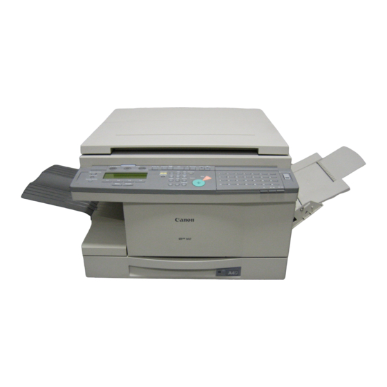
Page 18: Names Of Parts
Main unit ADF standard equipment model [10] Figure 1-301 Figure 1-302 Copyboard cover model [10] Figure 1-303 Figure 1-304 Cassette feeder (accessory) Figure 1-305 COPYRIGHT © 1999 CANON INC. CANON GP160 REV.0 FEB. 1999 PRINTED IN JAPAN (IMPRIME AU JAPON) - Page 19 [9] Printer unit [5] Cassette [10] Multi feeder tray Cassette feeder (accessory) [1] Cassette feeder [2] Cassette [3] Right door [4] Feeder lifting handle COPYRIGHT © 1999 CANON INC. CANON GP160 REV.0 FEB. 1999 PRINTED IN JAPAN (IMPRIME AU JAPON)
-
Page 20: Cross Sectional Diagram
[12] [16] [18] [10] [14] [20] [37] [29] [35] [31] [25] [23] [33] [27] [38] [24] [36] [34] [30] [32] [26] [28] Figure 1-306 COPYRIGHT © 1999 CANON INC. CANON GP160 REV.0 FEB. 1999 PRINTED IN JAPAN (IMPRIME AU JAPON) - Page 21 [36] Fixed pressure roller [20] Registration roller [37] Paper cassette (Main unit) [21] Multi-feeder pick-up roller [38] Paper cassette (Cassette feeder) [22] Multi-feeder tray COPYRIGHT © 1999 CANON INC. CANON GP160 REV.0 FEB. 1999 PRINTED IN JAPAN (IMPRIME AU JAPON)
-
Page 22: Operation Explanation
Start Copy Special Features OPER SYMBOLS Tone Return 29 ~ 56 57 ~ 84 [18] [19] [20] [21] [23] [25] [22] Figure 1-401 1-10 COPYRIGHT © 1999 CANON INC. CANON GP160 REV.0 FEB. 1999 PRINTED IN JAPAN (IMPRIME AU JAPON) - Page 23 One touch dial key. *: Not available on copiers not equipped with the fax function **: Not available on copiers not equipped with the printer function 1-11 COPYRIGHT © 1999 CANON INC. CANON GP160 REV.0 FEB. 1999 PRINTED IN JAPAN (IMPRIME AU JAPON)
- Page 24 Creates a space between rows of numbers or characters. Shift key Use to selecting items on the control panel. *: Not available on copiers not equipped with the fax function 1-12 COPYRIGHT © 1999 CANON INC. CANON GP160 REV.0 FEB. 1999 PRINTED IN JAPAN (IMPRIME AU JAPON)
-
Page 25: Basic Operation
Punch hole erasing ments. 2 in 1 copy Inputs the document size and paper size and designates 2 in 1 copying. Table 1-402 1-13 COPYRIGHT © 1999 CANON INC. CANON GP160 REV.0 FEB. 1999 PRINTED IN JAPAN (IMPRIME AU JAPON) -
Page 26: User Mode
01 ROTARY PULSE 03 OFF 02 TOUCH TONE 11 R-KEY SETTING 01 PSTN 02 PBX 01 PREFIX 02 HOOKING 03 EARTH CONNECTION Figure 1-403 1-14 COPYRIGHT © 1999 CANON INC. CANON GP160 REV.0 FEB. 1999 PRINTED IN JAPAN (IMPRIME AU JAPON) - Page 27 01 OFF 02 ON 03 TX SETTINGS 01 ECM TX 01 ON 02 OFF 02 PAUSE TIME (01 ~ 15) 02 SEC Figure 1-404 1-15 COPYRIGHT © 1999 CANON INC. CANON GP160 REV.0 FEB. 1999 PRINTED IN JAPAN (IMPRIME AU JAPON)
- Page 28 07 STAMP ACTION 01 DIRECT & MEMORY TX 02 DIRECT TX 04 RX SETTINGS 01 ON 01 ECM RX 02 OFF Figure 1-405 1-16 COPYRIGHT © 1999 CANON INC. CANON GP160 REV.0 FEB. 1999 PRINTED IN JAPAN (IMPRIME AU JAPON)
- Page 29 02 OFF 02 ON 04 RX PAGE FOOTER 01 OFF 02 ON 05 N ON ONE PRINT 01 OFF 02 ON Figure 1-406 1-17 COPYRIGHT © 1999 CANON INC. CANON GP160 REV.0 FEB. 1999 PRINTED IN JAPAN (IMPRIME AU JAPON)
- Page 30 *1 Even when the [NAME STACK SIZE] is set to [OFF], if [STACK BYPASS] is selected by [CASSETTE ELIGIBLTY] or [SET REPORT CASSETTE], [STACK BYPASS] will automatically come [ON] Figure 1-407 1-18 COPYRIGHT © 1999 CANON INC. CANON GP160 REV.0 FEB. 1999 PRINTED IN JAPAN (IMPRIME AU JAPON)
- Page 31 09 11 x 17 02 ON 10 LTR 11 LTRR 12 LGL *1 Setting is only possible when a option cassette feeder is installed. Figure 1-408 1-19 COPYRIGHT © 1999 CANON INC. CANON GP160 REV.0 FEB. 1999 PRINTED IN JAPAN (IMPRIME AU JAPON)
- Page 32 *1 Setting is only possible when a cassette feeder is installed. *2 When creating a confidential mail box, it is necessary to set a password. Figure 1-409 1-20 COPYRIGHT © 1999 CANON INC. CANON GP160 REV.0 FEB. 1999 PRINTED IN JAPAN (IMPRIME AU JAPON)
- Page 33 03 DELETE FILE (00 ~ 99) PASSWORD ENTER * When creating a relay box, it is necessary to set a password. Figure 1-410 1-21 COPYRIGHT © 1999 CANON INC. CANON GP160 REV.0 FEB. 1999 PRINTED IN JAPAN (IMPRIME AU JAPON)
- Page 34 02 ON 02 TX DOCUMENT 01 RECEIVED DOCUMENT 01 NOT TRANSMIT 02 TRANSMIT 02 SCAN DOCUMENT 01 NOT TRANSMIT 02 TRANSMIT Figure 1-411 1-22 COPYRIGHT © 1999 CANON INC. CANON GP160 REV.0 FEB. 1999 PRINTED IN JAPAN (IMPRIME AU JAPON)
- Page 35 02 TRANSMIT PASSWORD ENTER 03 DELETE FILE (00~99) * When creating an all-purpose box, it is necessary to set a password. Figure 1-412 1-23 COPYRIGHT © 1999 CANON INC. CANON GP160 REV.0 FEB. 1999 PRINTED IN JAPAN (IMPRIME AU JAPON)
- Page 36 *2 When creating a fixed time polling box, it is necessary to set a password. *3 When creating a polling box, it is necessary to set a password. Figure 1-413 1-24 COPYRIGHT © 1999 CANON INC. CANON GP160 REV.0 FEB. 1999 PRINTED IN JAPAN (IMPRIME AU JAPON)
- Page 37 04 SELECT ORIG UNIT 01 OFF 02 ON * When creating a transfer box, it is necessary to set a password. Figure 1-414 1-25 COPYRIGHT © 1999 CANON INC. CANON GP160 REV.0 FEB. 1999 PRINTED IN JAPAN (IMPRIME AU JAPON)
- Page 38 *1 When creating a transfer box, it is necessary to set a password. *2 Necessary when management password has been registered. Figure 1-415 1-26 COPYRIGHT © 1999 CANON INC. CANON GP160 REV.0 FEB. 1999 PRINTED IN JAPAN (IMPRIME AU JAPON)
- Page 39 09 RX PASSWORD 06 33600bps 10 ENERGY SAVER 01 ON (03~30) 03 MIN. 02 OFF 11 PHONE NO.CHECK 01 OFF 02 NO Figure 1-416 1-27 COPYRIGHT © 1999 CANON INC. CANON GP160 REV.0 FEB. 1999 PRINTED IN JAPAN (IMPRIME AU JAPON)
- Page 40 (050~200) 100% 03 STANDARD COPY QTY (01~99) 01 (01~20) 02mm 04 FRAME ERASE WIDTH 01 ON 05 AUTO SORT 02 OFF Figure 1-417 1-28 COPYRIGHT © 1999 CANON INC. CANON GP160 REV.0 FEB. 1999 PRINTED IN JAPAN (IMPRIME AU JAPON)
- Page 41 05 POLLING RX 01 PASSWORD 02 SUBADDRESS 03 GROUP DIAL (01~56) 01 TEL NUMBER ENTRY 02 NAME 03 TX TIME SETTING (5TIMES) Figure 1-418 1-29 COPYRIGHT © 1999 CANON INC. CANON GP160 REV.0 FEB. 1999 PRINTED IN JAPAN (IMPRIME AU JAPON)
- Page 42 08 PORTUGUESE 09 NORWEGIAN 10 SWEDISH 11 DANISH 12 SLOVENE *1 Setting is only possible when a option cassette feeder is installed. Figure 1-419 1-30 COPYRIGHT © 1999 CANON INC. CANON GP160 REV.0 FEB. 1999 PRINTED IN JAPAN (IMPRIME AU JAPON)
- Page 43 (050~200) 100% 12 STANDARD COPY QTY (01~99) 01 (01~20) 02mm 13 FRAME ERASE WIDTH 01 ON 14 AUTO SORT 02 OFF Figure 1-420 1-31 COPYRIGHT © 1999 CANON INC. CANON GP160 REV.0 FEB. 1999 PRINTED IN JAPAN (IMPRIME AU JAPON)
-
Page 44: Routine Maintenance To Be Carried Out By The User
1) Using the special tools provided, clean the separation static charge eliminator. 2) Clean away the paper dust from the area around the registration roller (refer to the diagram below). Figure 1-501 1-32 COPYRIGHT © 1999 CANON INC. CANON GP160 REV.0 FEB. 1999 PRINTED IN JAPAN (IMPRIME AU JAPON) -
Page 45: Safety
APPARECCHIO LASER DI CLASSE 1 APPARECCHIO LASER DI CLASSE 1 IN ACCORDO CON LA NORMA IN ACCORDO CON LA NORMA CEI 76-2 CEI 76-2 Figure 1-601 1-33 COPYRIGHT © 1999 CANON INC. CANON GP160 REV.0 FEB. 1999 PRINTED IN JAPAN (IMPRIME AU JAPON) - Page 46 THIS PRODUCT CONFORMS WITH CQRH RADIATION PERFORMANCE STANDARD 21CFR CHAPTER 1 SUBCHAPTER J. Figure 1-602 Note Part of this information may differ depending on the product model. 1-34 COPYRIGHT © 1999 CANON INC. CANON GP160 REV.0 FEB. 1999 PRINTED IN JAPAN (IMPRIME AU JAPON)
-
Page 47: Handling The Laser Unit
The above diagram is equipped with an ADF unit. The main units construction is the same for units whether equipped with the ADF units, or not. 1-35 COPYRIGHT © 1999 CANON INC. CANON GP160 REV.0 FEB. 1999 PRINTED IN JAPAN (IMPRIME AU JAPON) -
Page 48: Toner Safety
Also, this toner decomposes easily with vinyl material, therefore avoid contact. Caution Never throw the toner into fire - there is a danger of explosion. 1-36 COPYRIGHT © 1999 CANON INC. CANON GP160 REV.0 FEB. 1999 PRINTED IN JAPAN (IMPRIME AU JAPON) -
Page 49: Copying Process
8. Drum cleaning Cartridge 4. Transfer Multi feeder Registration 6. Re-charge 5. Separation Delivery 7. Fixing eliminator Paper flow Cassette Drum rotation direction Figure 1-702 1-37 COPYRIGHT © 1999 CANON INC. CANON GP160 REV.0 FEB. 1999 PRINTED IN JAPAN (IMPRIME AU JAPON) - Page 50 DC bias is applied to the back of the paper. Fixing film Paper + + + + + + + + + + + + Re-charge eliminator DC bias Figure 1-703 1-38 COPYRIGHT © 1999 CANON INC. CANON GP160 REV.0 FEB. 1999 PRINTED IN JAPAN (IMPRIME AU JAPON)
- Page 51 BASIC OPERATION ........2-1 III. BASIC SEQUENCES.......2-4 A. Function configuration......2-1 IV. MAIN MOTOR..........2-5 B. Copy operation overview ....2-2 PRINCIPAL CIRCUIT PCB ELECTRICAL CIRCUIT OVERVIEW ..2-3 INPUT/OUTPUT........2-6 COPYRIGHT © 1999 CANON INC. CANON GP160 REV.0 FEB. 1999 PRINTED IN JAPAN (IMPRIME AU JAPON)
-
Page 53: Basic Operation
<Pick-up feeding system> Cassette feeder 1 Accessory Cassette feeder 2 Cassette feeder 3 *: Only applicable for units equipped with a fax function. Figure 2-101 COPYRIGHT © 1999 CANON INC. CANON GP160 REV.0 FEB. 1999 PRINTED IN JAPAN (IMPRIME AU JAPON) -
Page 54: Copy Operation Overview
*2 Sheet mode is when the document is set in the ADF and then copied. Table 2-101 Reference: When copying using the multi-feeder pick-up, memory copying will take place no mat- ter what conditions are in effect. COPYRIGHT © 1999 CANON INC. CANON GP160 REV.0 FEB. 1999 PRINTED IN JAPAN (IMPRIME AU JAPON) -
Page 55: Electrical Circuit Overview
• Motor, clutch sensor, etc., load control • High voltage output control • Cassette feeder operation control • Jam detection • Laser scanner drive control Table 2-202 COPYRIGHT © 1999 CANON INC. CANON GP160 REV.0 FEB. 1999 PRINTED IN JAPAN (IMPRIME AU JAPON) -
Page 56: Basic Sequences
CHAPTER 2 BASIC OPERATION III. BASIC SEQUENCES Figure 2-301 COPYRIGHT © 1999 CANON INC. CANON GP160 REV.0 FEB. 1999 PRINTED IN JAPAN (IMPRIME AU JAPON) -
Page 57: Main Motor
7. Check the condition of the main motor malfunction using the status 35 feeding unit malfunction detailed status Bit 6. COPYRIGHT © 1999 CANON INC. CANON GP160 REV.0 FEB. 1999 PRINTED IN JAPAN (IMPRIME AU JAPON) -
Page 58: Principal Circuit Pcb Input/Output
An actual check is not possible, therefore an explanation Control panel PCB of the signal name has been omitted. Control panel sub Figure 2-501 COPYRIGHT © 1999 CANON INC. CANON GP160 REV.0 FEB. 1999 PRINTED IN JAPAN (IMPRIME AU JAPON) - Page 59 *1 This function only applies to units equipped with the ADF. *2 Is only installed if the unit is equipped with a FAX function. COPYRIGHT © 1999 CANON INC. CANON GP160 REV.0 FEB. 1999 PRINTED IN JAPAN (IMPRIME AU JAPON)
- Page 60 PS501S* is not in PS501) -2 TSTON* When the switch is pushed: “0” Test print output switch SW501 Sensor printed circuit board Figure 2-503 COPYRIGHT © 1999 CANON INC. CANON GP160 REV.0 FEB. 1999 PRINTED IN JAPAN (IMPRIME AU JAPON)
- Page 61 Laser scanner motor J304-12 BD PCB BD input signal (pulse signal) Laser scanner unit Laser driver Refer to P.5-4 J308-7 FM301 Refer to P.9-7 Figure 2-504 COPYRIGHT © 1999 CANON INC. CANON GP160 REV.0 FEB. 1999 PRINTED IN JAPAN (IMPRIME AU JAPON)
- Page 62 High-voltage output circuit Transfer charging roller (refer to P.9-4) JH404 Separation static charge eliminator JH405 Re-charge eliminator JH406 Remaining toner sensor Figure 2-505 2-10 COPYRIGHT © 1999 CANON INC. CANON GP160 REV.0 FEB. 1999 PRINTED IN JAPAN (IMPRIME AU JAPON)
-
Page 63: Exposure System
B. Exposure system sequence ....3-2 III. DISASSEMBLY, ASSEMBLY ....3-5 SCANNER DRIVE SYSTEM....3-3 A. Scanning lamp ........3-6 A. Document scanner motor....3-3 B. Document scanning motor ....3-8 COPYRIGHT © 1999 CANON INC. CANON GP160 REV.0 FEB. 1999 PRINTED IN JAPAN (IMPRIME AU JAPON) -
Page 65: Chapter 3 Exposure System
Analog processor PCB Figure 3-101 Document scanner motor (M701) Light-blocking plate Scanner home position Forward sensor (PS101) Mirror mount 1 Mirror mount 2 Backward Figure 3-102 COPYRIGHT © 1999 CANON INC. CANON GP160 REV.0 FEB. 1999 PRINTED IN JAPAN (IMPRIME AU JAPON) -
Page 66: Exposure System Sequence
Exposure system sequence Start key ON STBY INTR SCFW SCFW LSTR STBY Document scanner motor (M701) Scanner home position sensor (PS101) Scanning lamp Figure 3-103 COPYRIGHT © 1999 CANON INC. CANON GP160 REV.0 FEB. 1999 PRINTED IN JAPAN (IMPRIME AU JAPON) -
Page 67: Scanner Drive System
Related service mode By setting service mode>#10 CS SET>, the Mirror 1 mount will be moved to the fac- tory setting position. Figure 3-201 COPYRIGHT © 1999 CANON INC. CANON GP160 REV.0 FEB. 1999 PRINTED IN JAPAN (IMPRIME AU JAPON) -
Page 68: Scanning Lamp Control
[1] LMPON: Scanning lamp drive signal Related service mode Service mode>TEST MODE>5:AGING TEST (Number Key 5) Scanning lamp lighting, ADF motor operation, oblique line pattern print Figure 3-202 COPYRIGHT © 1999 CANON INC. CANON GP160 REV.0 FEB. 1999 PRINTED IN JAPAN (IMPRIME AU JAPON) -
Page 69: Disassembly, Assembly
PCB. This will protect the PCB from any electrostatic damage. 8. When disassembling, do not remove screws which have been paint-locked. COPYRIGHT © 1999 CANON INC. CANON GP160 REV.0 FEB. 1999 PRINTED IN JAPAN (IMPRIME AU JAPON) -
Page 70: Scanning Lamp
10cm to the right. Figure 3-301 6) Remove the installation screw [3], and then remove the inverter PCB cover [4] Figure 3-302 COPYRIGHT © 1999 CANON INC. CANON GP160 REV.0 FEB. 1999 PRINTED IN JAPAN (IMPRIME AU JAPON) - Page 71 2 installa- tion pins. 9) Removed a scanning lamp at slide. Figure 3-304 COPYRIGHT © 1999 CANON INC. CANON GP160 REV.0 FEB. 1999 PRINTED IN JAPAN (IMPRIME AU JAPON)
-
Page 72: Document Scanning Motor
ADF. operation of the scanner. The configuration of the main unit is also the same for units which are not equipped with an ADF. COPYRIGHT © 1999 CANON INC. CANON GP160 REV.0 FEB. 1999 PRINTED IN JAPAN (IMPRIME AU JAPON) - Page 73 ABC circuit .........4-3 G. Binarisation ........4-9 III. DIGITAL IMAGE PROCESSING....4-4 IV. DISASSEMBLY, ASSEMBLY ....4-10 A. Overview ..........4-4 A. CCD unit ..........4-11 B. Shading correction ......4-5 COPYRIGHT © 1999 CANON INC. CANON GP160 REV.0 FEB. 1999 PRINTED IN JAPAN (IMPRIME AU JAPON)
-
Page 75: Chapter 4 Image Processing System
Shading Binari- processing correction conversion zation circuit circuit circuit Laser driver DC controller Laser Laser Photosensitive exposure drive circuit drum control circuit Figure 4-101 COPYRIGHT © 1999 CANON INC. CANON GP160 REV.0 FEB. 1999 PRINTED IN JAPAN (IMPRIME AU JAPON) -
Page 76: Overview
Even number pixel signal Reference voltage circuit ABC circuit ABC setting signal ABC circuit off signal Analog signal setting signal Clock pulse Figure 4-201 COPYRIGHT © 1999 CANON INC. CANON GP160 REV.0 FEB. 1999 PRINTED IN JAPAN (IMPRIME AU JAPON) -
Page 77: A-D Conversion Circuit / Abc Circuit
FFH (white) FFH (white) Output level 00H (black) 00H (black) : White background document density range : Coloured background document density range Figure 4-202 COPYRIGHT © 1999 CANON INC. CANON GP160 REV.0 FEB. 1999 PRINTED IN JAPAN (IMPRIME AU JAPON) -
Page 78: Digital Image Processing
Image processor PCB Magnifi- • Edge Analog Shading cation ratio emphasis processor correction processing • Smoothing Logarithmic Density Binarization controller correction processing Figure 4-301 COPYRIGHT © 1999 CANON INC. CANON GP160 REV.0 FEB. 1999 PRINTED IN JAPAN (IMPRIME AU JAPON) -
Page 79: Shading Correction
• For Fax transmissions, shading correction takes place before scanning the first page. (Shading correction only takes place once regardless of the number of pages). COPYRIGHT © 1999 CANON INC. CANON GP160 REV.0 FEB. 1999 PRINTED IN JAPAN (IMPRIME AU JAPON) - Page 80 Figure 4-303 Related service mode Shading automatic adjustment: Control panel RMSW ON, Service mode> TEST MODE>2:CCD (Numeric key 2 > Numeric key 8 > COPYRIGHT © 1999 CANON INC. CANON GP160 REV.0 FEB. 1999 PRINTED IN JAPAN (IMPRIME AU JAPON)
-
Page 81: Magnification Ratio Process
White After output Black Black Horizontal scanning direction Horizontal scanning direction White White After output After output Edge emphasis process Smoothing process Figure 4-304 COPYRIGHT © 1999 CANON INC. CANON GP160 REV.0 FEB. 1999 PRINTED IN JAPAN (IMPRIME AU JAPON) -
Page 82: Logarithmic Correction
In order to correct this, the level is adjusted, using the correction curve shown in Figure 4-306. CCD output Output level Black White Input level Document density Figure 4-305 Figure 4-306 COPYRIGHT © 1999 CANON INC. CANON GP160 REV.0 FEB. 1999 PRINTED IN JAPAN (IMPRIME AU JAPON) -
Page 83: Half Tone Density Processing
The binarisation technique which the unit uses employs is the error diffusion system. The data which have been binarised are sent to the DC controller PCB with a recording resolution of 1200 x 600pdi equivalent. COPYRIGHT © 1999 CANON INC. CANON GP160 REV.0 FEB. 1999 PRINTED IN JAPAN (IMPRIME AU JAPON) -
Page 84: Disassembly, Assembly
PCB. This will protect the PCB from any electrostatic damage. 8. When disassembling, do not remove screws which have been paint-locked. 4-10 COPYRIGHT © 1999 CANON INC. CANON GP160 REV.0 FEB. 1999 PRINTED IN JAPAN (IMPRIME AU JAPON) -
Page 85: Ccd Unit
3) Remove the analog processor PCB connector [3] and flat cable [4]. 4) Remove the 4 installation screws [5] and then remove the CCD unit. Figure 4-402 4-11 COPYRIGHT © 1999 CANON INC. CANON GP160 REV.0 FEB. 1999 PRINTED IN JAPAN (IMPRIME AU JAPON) -
Page 87: Laser Exposure System
B. BD generation / detection ....5-3 A. Operation outline........5-6 III. LASER DRIVER CIRCUIT .......5-4 DISASSEMBLY, ASSEMBLY ....5-7 A. Operation ...........5-4 A. Laser scanner unit ......5-8 COPYRIGHT © 1999 CANON INC. CANON GP160 REV.0 FEB. 1999 PRINTED IN JAPAN (IMPRIME AU JAPON) -
Page 89: Chapter 5 Laser Exposure System
Lens CCD light receiving unit Analog processor PCB Laser mirror Laser Laser beam DC controller driver Laser scanner unit Photo- sensitive drum Figure 5-101 COPYRIGHT © 1999 CANON INC. CANON GP160 REV.0 FEB. 1999 PRINTED IN JAPAN (IMPRIME AU JAPON) - Page 90 The printer status is displayed as follows: Service mode > TEST MODE> 6: FACULTY TEST>6-3: SENSOR> Press Numeric key 5. Check the main motor fault condition by status 8 service technician call status Bit 2. COPYRIGHT © 1999 CANON INC. CANON GP160 REV.0 FEB. 1999 PRINTED IN JAPAN (IMPRIME AU JAPON)
-
Page 91: Bd Signal Generation
Polygon mirror (6 sided) Laser scanner unit Laser forced light emission signal (LON*) Horizontal sync. DC controller PCB Image processor signal (BDO) Figure 5-201 COPYRIGHT © 1999 CANON INC. CANON GP160 REV.0 FEB. 1999 PRINTED IN JAPAN (IMPRIME AU JAPON) -
Page 92: Laser Driver Circuit
This laser control takes place constantly during laser beam emis- sion. COPYRIGHT © 1999 CANON INC. CANON GP160 REV.0 FEB. 1999 PRINTED IN JAPAN (IMPRIME AU JAPON) - Page 93 [2] VDO*/VDO : Video signal [3] 600* : Laser beam changeover signal [4] BDI* : BD input signal [5] VDOUT* : Video out signal Figure 5-301 COPYRIGHT © 1999 CANON INC. CANON GP160 REV.0 FEB. 1999 PRINTED IN JAPAN (IMPRIME AU JAPON)
-
Page 94: Laser Scanner Motor Control
Laser scanner motor driver PCB Scanner motor acceleration signal (ACC*) Scanner motor deceleration Motor drive circuit signal (DEC*) 6 sided mirror Laser scanner motor Figure 5-401 COPYRIGHT © 1999 CANON INC. CANON GP160 REV.0 FEB. 1999 PRINTED IN JAPAN (IMPRIME AU JAPON) -
Page 95: Disassembly, Assembly
PCB. This will protect the PCB from any electrostatic damage. 8. When disassembling, do not remove screws which have been paint-locked. COPYRIGHT © 1999 CANON INC. CANON GP160 REV.0 FEB. 1999 PRINTED IN JAPAN (IMPRIME AU JAPON) -
Page 96: Laser Scanner Unit
3) Remove the 3 connectors [3] which are connected to the laser scanner unit. Then, after removing the 4 installation screws [4], remove the laser scanner unit [5]. Figure 5-502 COPYRIGHT © 1999 CANON INC. CANON GP160 REV.0 FEB. 1999 PRINTED IN JAPAN (IMPRIME AU JAPON) -
Page 97: Image Formation System
TRANSFER CHARGING ROLLER BIAS VI. RE-CHARGE BIAS CONTROL....6-8 CONTROL..........6-4 A. Operation ...........6-8 A. Overview ..........6-4 VII. CARTRIDGE DETECTION ......6-9 B. Bias control ........6-5 A. Operation ...........6-9 COPYRIGHT © 1999 CANON INC. CANON GP160 REV.0 FEB. 1999 PRINTED IN JAPAN (IMPRIME AU JAPON) -
Page 99: Chapter 6 Image Formation System
Primary charging roller JH406 Toner sensor Blade Drum Developing cylinder High- voltage output unit Transfer charging roller Charge JH403 eliminator Re-charge JH404 eliminator JH405 Figure 6-101 COPYRIGHT © 1999 CANON INC. CANON GP160 REV.0 FEB. 1999 PRINTED IN JAPAN (IMPRIME AU JAPON) - Page 100 CHAPTER 6 IMAGE FORMATION SYSTEM High voltage related output sequence Conditions: When copying 2 sheets of A4 size paper. Figure 6-102 COPYRIGHT © 1999 CANON INC. CANON GP160 REV.0 FEB. 1999 PRINTED IN JAPAN (IMPRIME AU JAPON)
-
Page 101: Primary Charging Roller Bias Control
[3] DCPWM Compari- DC drive DC voltage [1] PRACON: AC control signal control [2] 1200DPI: Bias switching signal [3] DCWM: DC control signal Figure 6-201 COPYRIGHT © 1999 CANON INC. CANON GP160 REV.0 FEB. 1999 PRINTED IN JAPAN (IMPRIME AU JAPON) -
Page 102: Transfer Charging Roller Bias Control
Paper interval bias When performing continuous printing, the bias value is lowered to prevent the toner between the paper adhering to the transfer charging roller. COPYRIGHT © 1999 CANON INC. CANON GP160 REV.0 FEB. 1999 PRINTED IN JAPAN (IMPRIME AU JAPON) -
Page 103: Bias Control
Negative [3] TRNFOT bias generation [1] TRPWM: Positive bias drive signal [2] 1200DPI: Bias switching signal [3] TRNFOT: Negative bias switching signal Figure 6-301 COPYRIGHT © 1999 CANON INC. CANON GP160 REV.0 FEB. 1999 PRINTED IN JAPAN (IMPRIME AU JAPON) -
Page 104: Separation Static Charge Eliminator Bias Control
T406) (IC301) charge eliminator Bias [2] 1200DPI switching [1] DSCON: Static charge eliminator circuit bias ON signal [2] 1200DPI: Bias switching signal Figure 6-401 COPYRIGHT © 1999 CANON INC. CANON GP160 REV.0 FEB. 1999 PRINTED IN JAPAN (IMPRIME AU JAPON) -
Page 105: Developing Bias Control
[2] DVDUP tive circuit DC bias generation circuit DC bias detection circuit [1] DVACON: AC bias drive signal [2] DVDUP: DC ON/OFF signal Figure 6-501 COPYRIGHT © 1999 CANON INC. CANON GP160 REV.0 FEB. 1999 PRINTED IN JAPAN (IMPRIME AU JAPON) -
Page 106: Re-Charge Bias Control
[1] RECON circuit (transformer T407) (IC301) Bias [2] 1200DPI [1] RECON: Re-charge eliminator switching circuit bias ON signal [2] 1200DPI: Bias switching signal Figure 6-601 COPYRIGHT © 1999 CANON INC. CANON GP160 REV.0 FEB. 1999 PRINTED IN JAPAN (IMPRIME AU JAPON) -
Page 107: Cartridge Detection
(IC301) Antenna [2] TNRCHKT Toner cartridge output detection circuit [1] TNRCHKT: Developing bias AC output [2] TNRCHK: Antenna output signal Figure 6-701 COPYRIGHT © 1999 CANON INC. CANON GP160 REV.0 FEB. 1999 PRINTED IN JAPAN (IMPRIME AU JAPON) - Page 109 B. Multi-feeder pick-up mechanism ..7-8 C. Registration roller assembly.....7-33 C. Multi-feeder retry pick-up ....7-9 D. Feeder assembly ......7-35 D. Multi-feeder paper size setting ..7-10 COPYRIGHT © 1999 CANON INC. CANON GP160 REV.0 FEB. 1999 PRINTED IN JAPAN (IMPRIME AU JAPON)
-
Page 111: Chapter 7 Pick-Up/Feeding System
Table 7-102 PS304 PS302 PS301 PS306 PS501 PS305 PS303 Figure 7-101 COPYRIGHT © 1999 CANON INC. CANON GP160 REV.0 FEB. 1999 PRINTED IN JAPAN (IMPRIME AU JAPON) -
Page 112: Pick-Up Feeding Operation
[2] CL301D*: Vertical path roller clutch drive signal J307-3 [3] MMD*: Main motor drive signal CL301 [2] CL301D* Main motor [3] MMD* M601 Figure 7-201 COPYRIGHT © 1999 CANON INC. CANON GP160 REV.0 FEB. 1999 PRINTED IN JAPAN (IMPRIME AU JAPON) -
Page 113: Cassette Pick-Up Mechanism
(CL301), and paper is sent out to the registration roller assembly. Registration sensor Registration roller Vertical path roller clutch Registration clutch Vertical path roller Feeder roller Pick-up sensor Separation roller Pick-up roller Figure 7-301 COPYRIGHT © 1999 CANON INC. CANON GP160 REV.0 FEB. 1999 PRINTED IN JAPAN (IMPRIME AU JAPON) - Page 114 OFF. the pick-up solenoid being ON. Therefore (Pick-up/feed rollers are not rotating) the pick-up drive gear rotates. (Pick-up/feed rollers are rotating) Figure 7-302 COPYRIGHT © 1999 CANON INC. CANON GP160 REV.0 FEB. 1999 PRINTED IN JAPAN (IMPRIME AU JAPON)
-
Page 115: Retry Pick-Up
Start signal Retry pick-up sheet pick-up Pick-up solenoid (SL301) 3.0 sec. 3.0 sec. Pick-up sensor 3.0 sec. Normal Abnormal (PS303) Main motor (M601) Figure 7-303 COPYRIGHT © 1999 CANON INC. CANON GP160 REV.0 FEB. 1999 PRINTED IN JAPAN (IMPRIME AU JAPON) -
Page 116: Paper Size Detection
SW403 ™ ™ ™ ™ ™ ™ ™ ¡ ¡ ¡ ¡ SW404 ¡: Push switch pressed ™: Push switch not pressed Table 7-301 COPYRIGHT © 1999 CANON INC. CANON GP160 REV.0 FEB. 1999 PRINTED IN JAPAN (IMPRIME AU JAPON) -
Page 117: Multi-Feeder Pick-Up
J309-6 Multi-feeder paper signal (PS501S) sensor (PS501) Multi-feeder pick-up roller Registration roller J303-5 Registration sensor Lifter plate paper signal (PS302S) Pre-Registration sensor (PS302) Separation pad Figure 7-401 COPYRIGHT © 1999 CANON INC. CANON GP160 REV.0 FEB. 1999 PRINTED IN JAPAN (IMPRIME AU JAPON) -
Page 118: Multi-Feeder Pick-Up Mechanism
Multi-feeder pick-up roller drive axis Separation sub pad Multi-feeder pick-up roller Separation pad Separation sub pad Lifter plate push-up spring Lifter plate Figure 7-402 COPYRIGHT © 1999 CANON INC. CANON GP160 REV.0 FEB. 1999 PRINTED IN JAPAN (IMPRIME AU JAPON) -
Page 119: Multi-Feeder Retry Pick-Up
COPYRIGHT © 1999 CANON INC. CANON GP160 REV.0 FEB. 1999 PRINTED IN JAPAN (IMPRIME AU JAPON) -
Page 120: Multi-Feeder Paper Size Setting
In addition, the above methods a) and b) are the only 2 methods available when printing fax reception data on multi-feeder pick-up paper. 7-10 COPYRIGHT © 1999 CANON INC. CANON GP160 REV.0 FEB. 1999 PRINTED IN JAPAN (IMPRIME AU JAPON) - Page 121 Pick-up amount, and the drive is transmitted from the drive transmission motor causing rotation to begin. gear Pick-up drive axis gear Figure 7-403 7-11 COPYRIGHT © 1999 CANON INC. CANON GP160 REV.0 FEB. 1999 PRINTED IN JAPAN (IMPRIME AU JAPON)
-
Page 122: Paper Feeding Operation
[1] PS304S: Paper width detection signal [3] TOP*: Horizontal synchronized signal [2] PS301S: Paper leading edge detection signal [4] VDO/VDO*: Video signal Figure 7-501 7-12 COPYRIGHT © 1999 CANON INC. CANON GP160 REV.0 FEB. 1999 PRINTED IN JAPAN (IMPRIME AU JAPON) -
Page 123: Jam Detection
J306-8 PS306 Delivery sensor PS306S J308-5 PS501 Multi-feeder paper presence sensor PS501S J309-6 *1 Jack number on the DC controller PCB. Table 7-601 7-13 COPYRIGHT © 1999 CANON INC. CANON GP160 REV.0 FEB. 1999 PRINTED IN JAPAN (IMPRIME AU JAPON) -
Page 124: Types Of Jam
Pick-up solenoid (SL301) Pick up sensor jam check 3.0 sec. 3.0 sec. 3.0 sec. Pick-up sensor Normal Abnormal (PS303) Main motor (M601) Figure 7-602 7-14 COPYRIGHT © 1999 CANON INC. CANON GP160 REV.0 FEB. 1999 PRINTED IN JAPAN (IMPRIME AU JAPON) - Page 125 Registration sensor Registration sensor 2.3 sec. 2.3 sec. Abnormal Normal (PS302) (PS302) Main motor Main motor (M601) (M601) Figure 7-603 7-15 COPYRIGHT © 1999 CANON INC. CANON GP160 REV.0 FEB. 1999 PRINTED IN JAPAN (IMPRIME AU JAPON)
- Page 126 Figure 7-604 Start signal Pick-up sensor (PS303) Registration sensor jam check Registration sensor 2.0 sec. 2.0 sec. Abnormal (PS302) Main motor (M601) Figure 7-605 7-16 COPYRIGHT © 1999 CANON INC. CANON GP160 REV.0 FEB. 1999 PRINTED IN JAPAN (IMPRIME AU JAPON)
- Page 127 Registration sensor 1.5 sec. 1.5 sec.1.5 sec. 1.5 sec. (PS302) Main motor Abnormal (M601) Jam detection sequence for multiple sheet pick-up Figure 7-607 7-17 COPYRIGHT © 1999 CANON INC. CANON GP160 REV.0 FEB. 1999 PRINTED IN JAPAN (IMPRIME AU JAPON)
- Page 128 0.3 sec. Pick-up sensor (PS303) Registration sensor 2.5 sec. 2.5 sec. jam check Registration sensor Normal Abnormal (PS302) Main motor (M601) Figure 7-608 7-18 COPYRIGHT © 1999 CANON INC. CANON GP160 REV.0 FEB. 1999 PRINTED IN JAPAN (IMPRIME AU JAPON)
- Page 129 Registration clutch (CL302) 1.2 sec. 1.2 sec. Registration sensor jam check Paper leading edge Normal Abnormal sensor (PS302) Main motor (M601) Figure 7-610 7-19 COPYRIGHT © 1999 CANON INC. CANON GP160 REV.0 FEB. 1999 PRINTED IN JAPAN (IMPRIME AU JAPON)
- Page 130 Start signal Paper leading edge sensor (PS301) 6.7 sec. 6.7 sec. Paper leading edge Normal Abnormal sensor jam check Main motor (M601) Figure 7-612 7-20 COPYRIGHT © 1999 CANON INC. CANON GP160 REV.0 FEB. 1999 PRINTED IN JAPAN (IMPRIME AU JAPON)
- Page 131 Paper leading edge sensor (PS301) 5.0 sec. 5.0 sec. Delivery sensor (PS306) Delivery sensor Normal Abnormal jam check Main motor (M601) Figure 7-614 7-21 COPYRIGHT © 1999 CANON INC. CANON GP160 REV.0 FEB. 1999 PRINTED IN JAPAN (IMPRIME AU JAPON)
- Page 132 • Pick-up delay jam * • Paper leading edge sensor delay jam* * Jams at the time of cassette pick-up and multi-feeder pick-up. 7-22 COPYRIGHT © 1999 CANON INC. CANON GP160 REV.0 FEB. 1999 PRINTED IN JAPAN (IMPRIME AU JAPON)
-
Page 133: Disassembly, Assembly
PCB. This will protect the PCB from any electrostatic damage. 8. When disassembling, do not remove screws which have been paint-locked. 7-23 COPYRIGHT © 1999 CANON INC. CANON GP160 REV.0 FEB. 1999 PRINTED IN JAPAN (IMPRIME AU JAPON) -
Page 134: Cassette Feeding Assembly
Figure 7-701 Reference: The pick-up roller’s installation posi- tion is indicated in Figure 7-702 Installation location Figure 7-702 7-24 COPYRIGHT © 1999 CANON INC. CANON GP160 REV.0 FEB. 1999 PRINTED IN JAPAN (IMPRIME AU JAPON) - Page 135 [4]. The feed roller is removed from the cassette insertion opening and the separation roller is removed from the lower right side. Figure 7-704 7-25 COPYRIGHT © 1999 CANON INC. CANON GP160 REV.0 FEB. 1999 PRINTED IN JAPAN (IMPRIME AU JAPON)
- Page 136 5) Remove the 4 installation screws [6] and the multi-feeder pick-up solenoid [7] connector. Then remove the multi- feeder drive unit [8]. Figure 7-706 7-26 COPYRIGHT © 1999 CANON INC. CANON GP160 REV.0 FEB. 1999 PRINTED IN JAPAN (IMPRIME AU JAPON)
- Page 137 10) Remove the tension spring from the rear side printer unit pressure lever [18], then slightly slide the pressure lever together with the axis. [17] [18] [16] Figure 7-709 7-27 COPYRIGHT © 1999 CANON INC. CANON GP160 REV.0 FEB. 1999 PRINTED IN JAPAN (IMPRIME AU JAPON)
- Page 138 2) Remove the installation screw and then remove the pick-up solenoid. Figure 7-711 7-28 COPYRIGHT © 1999 CANON INC. CANON GP160 REV.0 FEB. 1999 PRINTED IN JAPAN (IMPRIME AU JAPON)
- Page 139 When installing the gear, refer to the diagram below and confirm the gear’s positioning. Pick-up roller drive relay gear (cogless gear) Pick-up drive gear (cogless gear) (Grey area) Figure 7-713 7-29 COPYRIGHT © 1999 CANON INC. CANON GP160 REV.0 FEB. 1999 PRINTED IN JAPAN (IMPRIME AU JAPON)
-
Page 140: Multi-Feeder Assembly
3) Remove the 3 installation screws [4], then remove the right cover [5]. Caution Take care not to damage the multi- feeder paper sensor lever. Figure 7-715 7-30 COPYRIGHT © 1999 CANON INC. CANON GP160 REV.0 FEB. 1999 PRINTED IN JAPAN (IMPRIME AU JAPON) - Page 141 4) Remove the 2 installation screws [1] and the connector [2], then remove the sensor PCB [3]. Figure 7-717 7-31 COPYRIGHT © 1999 CANON INC. CANON GP160 REV.0 FEB. 1999 PRINTED IN JAPAN (IMPRIME AU JAPON)
- Page 142 8) Open the lifting plate, rotate the sep- aration pad [8] and remove. Figure 7-720 7-32 COPYRIGHT © 1999 CANON INC. CANON GP160 REV.0 FEB. 1999 PRINTED IN JAPAN (IMPRIME AU JAPON)
-
Page 143: Registration Roller Assembly
[3]. Figure 7-721 4) Remove the 4 installation screws [4], then remove the registration roller unit. Figure 7-722 7-33 COPYRIGHT © 1999 CANON INC. CANON GP160 REV.0 FEB. 1999 PRINTED IN JAPAN (IMPRIME AU JAPON) - Page 144 CHAPTER 7 PICK-UP/FEEDING SYSTEM Construction of the registration roller assembly Lower registration guide plate Upper registration guide plate Registration pressure roller Registration roller Figure 7-723 7-34 COPYRIGHT © 1999 CANON INC. CANON GP160 REV.0 FEB. 1999 PRINTED IN JAPAN (IMPRIME AU JAPON)
-
Page 145: Feeder Assembly
DC controller PCB. If the feeder unit is installed after the DC controller PCB, there is the possibility that the high-voltage contact pins will become deformed. 7-35 COPYRIGHT © 1999 CANON INC. CANON GP160 REV.0 FEB. 1999 PRINTED IN JAPAN (IMPRIME AU JAPON) -
Page 147: I. Operational Overview
B. Fixing pressure roller cleaning ...8-1 detector ..........8-5 FIXING CONTROL........8-3 III. DISASSEMBLY, ASSEMBLY ....8-6 A. Fixing temperature control ....8-3 A. Removing the fixing assembly ...8-7 COPYRIGHT © 1999 CANON INC. CANON GP160 REV.0 FEB. 1999 PRINTED IN JAPAN (IMPRIME AU JAPON) -
Page 149: Operational Overview
Fixing film Delivery roller Fixing heater Fixing assembly inlet guide Cleaning roller Pressure roller Figure 8-101 COPYRIGHT © 1999 CANON INC. CANON GP160 REV.0 FEB. 1999 PRINTED IN JAPAN (IMPRIME AU JAPON) - Page 150 CHAPTER 8 FIXING SYSTEM DC controller PCB Main motor DC Power supply M601 Delivery sensor (PS306) Fixing heater Delivery roller Pressure roller Cleaning roller Figure 8-102 COPYRIGHT © 1999 CANON INC. CANON GP160 REV.0 FEB. 1999 PRINTED IN JAPAN (IMPRIME AU JAPON)
-
Page 151: Fixing Control
160 to 145 Tracing paper 130 to 100 1200 137 to 127 *1: USER MODE > 05 PRINTER SETTING > 10 SELECT PAPER Table 8-201 COPYRIGHT © 1999 CANON INC. CANON GP160 REV.0 FEB. 1999 PRINTED IN JAPAN (IMPRIME AU JAPON) - Page 152 IC304 unit J203-1 FSRTH FSRTM Thermo- switch THCHG 43 Q301 Fixing Pressure heater roller J201- J305-4 FSRTH Main Delivery M601 motor roller Figure 8-201 COPYRIGHT © 1999 CANON INC. CANON GP160 REV.0 FEB. 1999 PRINTED IN JAPAN (IMPRIME AU JAPON)
-
Page 153: Fixing Heater Safety Mechanism
When there was no detection of the zero cross signal while the heater was ON for 3 or more continuous seconds. COPYRIGHT © 1999 CANON INC. CANON GP160 REV.0 FEB. 1999 PRINTED IN JAPAN (IMPRIME AU JAPON) -
Page 154: Disassembly, Assembly
PCB. This will protect the PCB from any electrostatic damage. 8. When disassembling, do not remove screws which have been paint-locked. COPYRIGHT © 1999 CANON INC. CANON GP160 REV.0 FEB. 1999 PRINTED IN JAPAN (IMPRIME AU JAPON) -
Page 155: Removing The Fixing Assembly
When replacing the cover, be sure to Be sure to insert correctly. place the cover tab correctly in the “U” guide. Figure 8-302 COPYRIGHT © 1999 CANON INC. CANON GP160 REV.0 FEB. 1999 PRINTED IN JAPAN (IMPRIME AU JAPON) - Page 156 3) Remove the two screws [2], and remove the grounding cable. 4) Remove the two screws [3], and remove the fixing assembly. Figure 8-303 COPYRIGHT © 1999 CANON INC. CANON GP160 REV.0 FEB. 1999 PRINTED IN JAPAN (IMPRIME AU JAPON)
- Page 157 C. DC controller PCB......9-25 III. FAN ............9-7 D. Image processor PCB ......9-26 A. Rotation control mechanism ....9-7 E. DC power supply PCB .....9-27 IV. BACK-UP BATTERY........9-8 COPYRIGHT © 1999 CANON INC. CANON GP160 REV.0 FEB. 1999 PRINTED IN JAPAN (IMPRIME AU JAPON)
-
Page 159: Chapter 9 External/Auxiliary Mechanism
The liquid crystal display console is composed of 80 × 320dots. Control panel Control panel Image processor PCB 1 PCB 2 Control panel Key SW Key SW Slide SW IC15 Figure 9-101 COPYRIGHT © 1999 CANON INC. CANON GP160 REV.0 FEB. 1999 PRINTED IN JAPAN (IMPRIME AU JAPON) -
Page 160: Power Supply
Ratings for the fuses installed on the DC power supply PCB Electrical symbol Rating 15A 125V 15A 125V 5A 125V 5A 125V Table 9-202 COPYRIGHT © 1999 CANON INC. CANON GP160 REV.0 FEB. 1999 PRINTED IN JAPAN (IMPRIME AU JAPON) - Page 161 DC+5V Electrical loads Noise filter DC+12V Accessory function PCB Abnormality DC+5V detection printed DC+5V circuit DC+12V DC power supply PCB DC+24V DC+24V Figure 9-201 COPYRIGHT © 1999 CANON INC. CANON GP160 REV.0 FEB. 1999 PRINTED IN JAPAN (IMPRIME AU JAPON)
-
Page 162: High Voltage Power Supply Circuit
• Static charge eliminator bias (DC negative voltage) Please refer to chapter 6 “Image formation system” for more information regarding the control of each electrical load. COPYRIGHT © 1999 CANON INC. CANON GP160 REV.0 FEB. 1999 PRINTED IN JAPAN (IMPRIME AU JAPON) -
Page 163: Energy Save Function Control
DC power supply DC power supply ADF relay controller Electrical loads controller signal assembly DC power supply Control panel controller signal Figure 9-202 COPYRIGHT © 1999 CANON INC. CANON GP160 REV.0 FEB. 1999 PRINTED IN JAPAN (IMPRIME AU JAPON) - Page 164 • The pre-set report output time has arrived (for those machines fitted with the fax function). • The pre-set timer alarm time has arrived (for those machines fitted with the fax function). COPYRIGHT © 1999 CANON INC. CANON GP160 REV.0 FEB. 1999 PRINTED IN JAPAN (IMPRIME AU JAPON)
-
Page 165: Fan
Half-speed rotation signal FM301 J308-8 (HALFFM*) Drive circuit Fan motor drive signal (FMON) (IC301) Fan motor lock detection signal J308-7 (FMLOCK) J308-6 Figure 9-301 COPYRIGHT © 1999 CANON INC. CANON GP160 REV.0 FEB. 1999 PRINTED IN JAPAN (IMPRIME AU JAPON) -
Page 166: Back-Up Battery
When the batteries have been completely used up dispose of them in an appropriate manner (dispose them separately from normal garbage). Vanadium lithium secondary battery (BAT1) Image processor PCB Lithium battery (BAT2) Figure 9-401 COPYRIGHT © 1999 CANON INC. CANON GP160 REV.0 FEB. 1999 PRINTED IN JAPAN (IMPRIME AU JAPON) - Page 167 Memory Reference > Transmit document > Select document to transfer > Designate transfer destination > Select sender’s name > Transfer. COPYRIGHT © 1999 CANON INC. CANON GP160 REV.0 FEB. 1999 PRINTED IN JAPAN (IMPRIME AU JAPON)
- Page 168 Please press the set key on the control panel. The data stored in the con- trol memory will be reset to the factory settings. The unit will go into stand-by mode. 9-10 COPYRIGHT © 1999 CANON INC. CANON GP160 REV.0 FEB. 1999 PRINTED IN JAPAN (IMPRIME AU JAPON)
- Page 169 Should a fax be added to the main unit as an accessory, the JP1 must be changed to Jumper plug (JP1) Vanadium lithium secondary battery (BAT1) Image processor PCB Jumper plug (JP3) Lithium battery (BAT2) Figure 9-403 9-11 COPYRIGHT © 1999 CANON INC. CANON GP160 REV.0 FEB. 1999 PRINTED IN JAPAN (IMPRIME AU JAPON)
-
Page 170: Back-Up Data
Reduction / cassette selection settings, etc. CLEAR Scan count, print counter, etc. Version number, checksum, etc. #10. CS SET Revert to initial mirror mount settings. Table 9-402 9-12 COPYRIGHT © 1999 CANON INC. CANON GP160 REV.0 FEB. 1999 PRINTED IN JAPAN (IMPRIME AU JAPON) - Page 171 Transmission (memory transmission, report transmission) Delayed communications Delayed broadcast transmission Polling transmission Relay broadcast transmission Reception image Confidential reception Memory reception Table 9-404 9-13 COPYRIGHT © 1999 CANON INC. CANON GP160 REV.0 FEB. 1999 PRINTED IN JAPAN (IMPRIME AU JAPON)
- Page 172 System data list Table 9-406 c) Management data Item List name Activity management records Activity management report System dump records System dump list Table 9-407 9-14 COPYRIGHT © 1999 CANON INC. CANON GP160 REV.0 FEB. 1999 PRINTED IN JAPAN (IMPRIME AU JAPON)
- Page 173 1 and 2 • Group dial telephone number list 1 • System data list • Activity management report • System dump list Table 9-408 9-15 COPYRIGHT © 1999 CANON INC. CANON GP160 REV.0 FEB. 1999 PRINTED IN JAPAN (IMPRIME AU JAPON)
-
Page 174: Disassembly, Assembly
PCB. This will protect the PCB from any electrostatic damage. 8. When disassembling, do not remove screws which have been paint-locked. 9-16 COPYRIGHT © 1999 CANON INC. CANON GP160 REV.0 FEB. 1999 PRINTED IN JAPAN (IMPRIME AU JAPON) -
Page 175: Control Panel
3) Remove the 6 installation screws [3] from the left and right sides (two are attached to the grounding cable). Figure 9-502 Figure 9-503 9-17 COPYRIGHT © 1999 CANON INC. CANON GP160 REV.0 FEB. 1999 PRINTED IN JAPAN (IMPRIME AU JAPON) - Page 176 CHAPTER 9 EXTERNAL/AUXILIARY MECHANISM 4) Move the control panel forward, remove the 2 connectors [4], and remove the control panel. Figure 9-504 9-18 COPYRIGHT © 1999 CANON INC. CANON GP160 REV.0 FEB. 1999 PRINTED IN JAPAN (IMPRIME AU JAPON)
-
Page 177: Main Motor
When putting the cover on, while Insert correctly ensuring that you have placed the tab correctly in the ‘U’ guide, re-fit the cover to the unit. Figure 9-506 9-19 COPYRIGHT © 1999 CANON INC. CANON GP160 REV.0 FEB. 1999 PRINTED IN JAPAN (IMPRIME AU JAPON) - Page 178 If the printer unit is pulled out too quickly, there is a chance that it may fall out, so please be sure to pull it out slowly. 9-20 COPYRIGHT © 1999 CANON INC. CANON GP160 REV.0 FEB. 1999 PRINTED IN JAPAN (IMPRIME AU JAPON)
- Page 179 Be careful not to bend during removal and attachment of the printer unit Figure 9-510 9-21 COPYRIGHT © 1999 CANON INC. CANON GP160 REV.0 FEB. 1999 PRINTED IN JAPAN (IMPRIME AU JAPON)
- Page 180 Yellow rollers Figure 9-511 9-22 COPYRIGHT © 1999 CANON INC. CANON GP160 REV.0 FEB. 1999 PRINTED IN JAPAN (IMPRIME AU JAPON)
- Page 181 4) Remove the connector [4] from the main motor driver PCB. 5) Remove the 5 installation screws [5] and remove the main drive assembly [6]. Figure 9-513 9-23 COPYRIGHT © 1999 CANON INC. CANON GP160 REV.0 FEB. 1999 PRINTED IN JAPAN (IMPRIME AU JAPON)
- Page 182 [8] from the driver PCB. Figure 9-514 Reference: The structure of the main drive unit is depicted below. Main motor Figure 9-515 9-24 COPYRIGHT © 1999 CANON INC. CANON GP160 REV.0 FEB. 1999 PRINTED IN JAPAN (IMPRIME AU JAPON)
-
Page 183: Dc Controller Pcb
4) Remove the 4 installation screws [1]. Slide 5) Slide the DC controller PCB together with the support plate upwards. Then, pull it out towards the front. Figure 9-517 9-25 COPYRIGHT © 1999 CANON INC. CANON GP160 REV.0 FEB. 1999 PRINTED IN JAPAN (IMPRIME AU JAPON) -
Page 184: Image Processor Pcb
PCB and remove the 2 flat cables. 3) Remove the 4 installation screws [1], and remove the image processor PCB [2]. Figure 9-519 9-26 COPYRIGHT © 1999 CANON INC. CANON GP160 REV.0 FEB. 1999 PRINTED IN JAPAN (IMPRIME AU JAPON) -
Page 185: Dc Power Supply Pcb
DC power supply PCB. 5) Remove the 4 screws [1], and remove the DC power supply PCB. Figure 9-520 9-27 COPYRIGHT © 1999 CANON INC. CANON GP160 REV.0 FEB. 1999 PRINTED IN JAPAN (IMPRIME AU JAPON) - Page 187 IV. OPERATION OVERVIEW......10-5 B. Removing the pick-up/feeder/ A. Overview ..........10-5 separation motor ......10-12 B. Basic Sequence ......10-6 C. Removing the pick-up unit .....10-14 FEEDER MOTOR CONTROL....10-7 COPYRIGHT © 1999 CANON INC. CANON GP160 REV.0 FEB. 1999 PRINTED IN JAPAN (IMPRIME AU JAPON)
-
Page 189: Overview
Cassette feeder three level type Figure 10-102 The units depicted above are fitted with an ADF. Those units not equipped with an ADF are the same. 10-1 COPYRIGHT © 1999 CANON INC. CANON GP160 REV.0 FEB. 1999 PRINTED IN JAPAN (IMPRIME AU JAPON) - Page 190 Interface connector First cassette feeder Interface connector Second cassette feeder Interface connector Third cassette feeder Figure 10-103 10-2 COPYRIGHT © 1999 CANON INC. CANON GP160 REV.0 FEB. 1999 PRINTED IN JAPAN (IMPRIME AU JAPON)
-
Page 191: Chapter 10 Cassette Feeder
• Feeder motor (M651) • Paper supply sensor (PS652) (IC601) Switch Solenoid (SL651) • Cassette size detector • Pick-up solenoid switch Figure 10-201 10-3 COPYRIGHT © 1999 CANON INC. CANON GP160 REV.0 FEB. 1999 PRINTED IN JAPAN (IMPRIME AU JAPON) -
Page 192: Feeder Controller Pcb Input And Output
+24V J653-2 SL651 Pick-up solenoid SL651D * When “0”, the SL651 is ON J652-1 Refer to page 10-7 M651 Feeder motor Figure 10-301 10-4 COPYRIGHT © 1999 CANON INC. CANON GP160 REV.0 FEB. 1999 PRINTED IN JAPAN (IMPRIME AU JAPON) -
Page 193: Operation Overview
The unit depicted above is fitted with an ADF. The construction of the main unit is also the same for units not equipped with an ADF. 10-5 COPYRIGHT © 1999 CANON INC. CANON GP160 REV.0 FEB. 1999 PRINTED IN JAPAN (IMPRIME AU JAPON) -
Page 194: Basic Sequence
CHAPTER 10 CASSETTE FEEDER Basic Sequence Condition: When 2 pieces of A4 paper are picked up from the first level cassette feeder Figure 10-402 10-6 COPYRIGHT © 1999 CANON INC. CANON GP160 REV.0 FEB. 1999 PRINTED IN JAPAN (IMPRIME AU JAPON) -
Page 195: Feeder Motor Control
Feeder controller PCB +24V J652-4 A phase Feeder pulse M651 motor control Drive control circuit B phase pulse control Figure 10-501 10-7 COPYRIGHT © 1999 CANON INC. CANON GP160 REV.0 FEB. 1999 PRINTED IN JAPAN (IMPRIME AU JAPON) -
Page 196: Jam Detection
PS** PS302 PS304 PS301 PS305 PS303 PS652 PS651 PS652 PS651 PS652 PS651 PS651: Pick-up sensor PS652: Paper sensor PS302: Registration sensor Figure 10-601 10-8 COPYRIGHT © 1999 CANON INC. CANON GP160 REV.0 FEB. 1999 PRINTED IN JAPAN (IMPRIME AU JAPON) -
Page 197: Jam Sensing
Pick-up sensor jam check Approx. Approx. Approx. Pick-up sensor 3 seconds 3 seconds 3 seconds Normal Abnormal (PS651) Feeder motor (M651) Figure 10-602 10-9 COPYRIGHT © 1999 CANON INC. CANON GP160 REV.0 FEB. 1999 PRINTED IN JAPAN (IMPRIME AU JAPON) - Page 198 Feeder motor Feeder motor (M651) (M651) Note: In the figure, ‘a’ seconds stands for the timing count times displayed in table 10-601. Figure 10-603 10-10 COPYRIGHT © 1999 CANON INC. CANON GP160 REV.0 FEB. 1999 PRINTED IN JAPAN (IMPRIME AU JAPON)
-
Page 199: Disassembly, Assembly
PCB. This will protect the PCB from any electrostatic damage. 8. When disassembling, do not remove screws which have been paint-locked. 10-11 COPYRIGHT © 1999 CANON INC. CANON GP160 REV.0 FEB. 1999 PRINTED IN JAPAN (IMPRIME AU JAPON) -
Page 200: Removing The Feeder Motor
1) Grip the pick-up tab [1], and remove it from the pick-up drive shaft [2]. Lift up to remove Figure 10-702 10-12 COPYRIGHT © 1999 CANON INC. CANON GP160 REV.0 FEB. 1999 PRINTED IN JAPAN (IMPRIME AU JAPON) - Page 201 Be careful not to open the hinge too far. Figure 10-703 3) While gripping the claw, remove the feeder roller and the separation roller. Figure 10-704 10-13 COPYRIGHT © 1999 CANON INC. CANON GP160 REV.0 FEB. 1999 PRINTED IN JAPAN (IMPRIME AU JAPON)
-
Page 202: Removing The Pick-Up Unit
Figure 10-705 5) Remove the two screws [3], and remove the cord cover [4]. Figure 10-706 10-14 COPYRIGHT © 1999 CANON INC. CANON GP160 REV.0 FEB. 1999 PRINTED IN JAPAN (IMPRIME AU JAPON) - Page 203 [8]. Figure 10-708 8) Remove the 6 screws [9], and remove the pick-up unit. Figure 10-709 10-15 COPYRIGHT © 1999 CANON INC. CANON GP160 REV.0 FEB. 1999 PRINTED IN JAPAN (IMPRIME AU JAPON)
- Page 205 E. Attaching the tray/Power cord ..11-12 the packing materials .......11-4 F. Checking the Copy image ....11-13 B. Installing the cartridge ......11-5 G. Setting the Fax machine function ..11-13 COPYRIGHT © 1999 CANON INC. CANON GP160 REV.0 FEB. 1999 PRINTED IN JAPAN (IMPRIME AU JAPON)
-
Page 207: Chapter 11 Installation
F. The machine should be set up at least 10 cm away from the wall, and there should be enough space to perform maintenance on the machine. (Please refer to the following page “operation space overview”) 11-1 COPYRIGHT © 1999 CANON INC. CANON GP160 REV.0 FEB. 1999 PRINTED IN JAPAN (IMPRIME AU JAPON) - Page 208 The above figure shows a unit which has been fitted with an ADF. The required width and depth for performing maintenance on machines which are not fitted with an ADF is the same as for those depicted. 11-2 COPYRIGHT © 1999 CANON INC. CANON GP160 REV.0 FEB. 1999 PRINTED IN JAPAN (IMPRIME AU JAPON)
-
Page 209: Unpacking And Installation
E. Attach the tray and the power cord. F. Check the copy image. G. Set up the fax function (for those machines equipped with a fax function). 11-3 COPYRIGHT © 1999 CANON INC. CANON GP160 REV.0 FEB. 1999 PRINTED IN JAPAN (IMPRIME AU JAPON) -
Page 210: Opening The Package And Removing The Packing Materials
Don’t forget to remove the tie- wrap which has been fixed to the cassette’s paper lifting plate. Tie-wrap Paper lifting plate 11-4 COPYRIGHT © 1999 CANON INC. CANON GP160 REV.0 FEB. 1999 PRINTED IN JAPAN (IMPRIME AU JAPON) -
Page 211: Installing The Cartridge
Open the front cover of the main unit, and while pressing on the Printer assembly release lever, pull the printer assembly to the right. Front cover Release lever 11-5 COPYRIGHT © 1999 CANON INC. CANON GP160 REV.0 FEB. 1999 PRINTED IN JAPAN (IMPRIME AU JAPON) - Page 212 11-6 COPYRIGHT © 1999 CANON INC. CANON GP160 REV.0 FEB. 1999 PRINTED IN JAPAN (IMPRIME AU JAPON)
- Page 213 Cover Close the printer assembly cover, push it back into the main Cover unit, and close the front cover. Front cover Printer portion 11-7 COPYRIGHT © 1999 CANON INC. CANON GP160 REV.0 FEB. 1999 PRINTED IN JAPAN (IMPRIME AU JAPON)
-
Page 214: Loading Paper Into The Cassette
Paper width guide 11-8 COPYRIGHT © 1999 CANON INC. CANON GP160 REV.0 FEB. 1999 PRINTED IN JAPAN (IMPRIME AU JAPON) - Page 215 Paper lifting plate Adjust the position of the paper size sensor lever to fit the desired paper size. Paper size sensor lever 11-9 COPYRIGHT © 1999 CANON INC. CANON GP160 REV.0 FEB. 1999 PRINTED IN JAPAN (IMPRIME AU JAPON)
- Page 216 Confirm that the cassette tabs are holding the edges of the paper in place. 11-10 COPYRIGHT © 1999 CANON INC. CANON GP160 REV.0 FEB. 1999 PRINTED IN JAPAN (IMPRIME AU JAPON)
-
Page 217: Loading Paper Into The Multi-Feeder
Auxiliary tray After making the edges of the paper stack even, place the paper in the multi-feeder. 11-11 COPYRIGHT © 1999 CANON INC. CANON GP160 REV.0 FEB. 1999 PRINTED IN JAPAN (IMPRIME AU JAPON) -
Page 218: Attaching The Tray/Power Cord
Install the delivery tray provided. Document stacking tray Delivery tray Attach the included power cord to the AC inlet of the main unit. Power cord 11-12 COPYRIGHT © 1999 CANON INC. CANON GP160 REV.0 FEB. 1999 PRINTED IN JAPAN (IMPRIME AU JAPON) -
Page 219: Checking The Copy Image
This will display the #8 CLEAR screen. Using the shift keys , select ALL, and press the SET key. This activates the all-clear func- tion. 11-13 COPYRIGHT © 1999 CANON INC. CANON GP160 REV.0 FEB. 1999 PRINTED IN JAPAN (IMPRIME AU JAPON) - Page 220 Use the shift keys to move the cursor to enter the desired numbers. Press the set key. This sets the date and time. 11-14 COPYRIGHT © 1999 CANON INC. CANON GP160 REV.0 FEB. 1999 PRINTED IN JAPAN (IMPRIME AU JAPON)
- Page 221 NL. 11-15 COPYRIGHT © 1999 CANON INC. CANON GP160 REV.0 FEB. 1999 PRINTED IN JAPAN (IMPRIME AU JAPON)
- Page 222 005, and press the SET key. # 2 MENU Use the shift keys to select either OFF or ON, and press the SET key. 11-16 COPYRIGHT © 1999 CANON INC. CANON GP160 REV.0 FEB. 1999 PRINTED IN JAPAN (IMPRIME AU JAPON)
-
Page 223: Maintenance And Inspection
PARTS ...........12-1 B. Storage and handling when the III. BASIC SERVICING PROCEDURES ..12-2 packing seal has been opened ..12-4 IV. CARTRIDGE STORAGE AND HANDLING..........12-3 COPYRIGHT © 1999 CANON INC. CANON GP160 REV.0 FEB. 1999 PRINTED IN JAPAN (IMPRIME AU JAPON) -
Page 225: Chapter 12 Maintenance And Inspection
Table 12-201 Caution The information in the table above is only an estimate, and may be revised in the light of empirical data. 12-1 COPYRIGHT © 1999 CANON INC. CANON GP160 REV.0 FEB. 1999 PRINTED IN JAPAN (IMPRIME AU JAPON) -
Page 226: Basic Servicing Procedures
• Fixing assembly inlet guide Clean the copy board glass Make a test copy Tidy up around the unit Table 12-301 12-2 COPYRIGHT © 1999 CANON INC. CANON GP160 REV.0 FEB. 1999 PRINTED IN JAPAN (IMPRIME AU JAPON) -
Page 227: Cartridge Storage And Handling
Table 12-401 Temperature and humidity conditions for storage Caution The total warranty period is the period effective from the date of manufacture printed on the cartridge packing box. 12-3 COPYRIGHT © 1999 CANON INC. CANON GP160 REV.0 FEB. 1999 PRINTED IN JAPAN (IMPRIME AU JAPON) -
Page 228: Storage And Handling When The Packing Seal Has Been Opened
It is preferable to use up the cartridge before the expiration date, because after that date the cartridge image quality deteriorates. 12-4 COPYRIGHT © 1999 CANON INC. CANON GP160 REV.0 FEB. 1999 PRINTED IN JAPAN (IMPRIME AU JAPON) - Page 229 As shown in Figure 12-402, do not hold the cartridge vertically or upside down. Also, do not wave it about. Figure 12-402 12-5 COPYRIGHT © 1999 CANON INC. CANON GP160 REV.0 FEB. 1999 PRINTED IN JAPAN (IMPRIME AU JAPON)
- Page 230 Instruct the user to return used cartridges to a designated collection center. 12-6 COPYRIGHT © 1999 CANON INC. CANON GP160 REV.0 FEB. 1999 PRINTED IN JAPAN (IMPRIME AU JAPON)
- Page 231 1,500lux intensity light (normal light) for 5 minutes,. However, do not expose the cartridge to direct sunlight. The sun’s rays have a light intensity ranging from approximately 10,000lux to 30,000lux. 12-7 COPYRIGHT © 1999 CANON INC. CANON GP160 REV.0 FEB. 1999 PRINTED IN JAPAN (IMPRIME AU JAPON)
-
Page 233: Troubleshooting
A. User reports .........13-142 IV. ELECTRICAL PARTS POSITIONS/ B. Service report.......13-145 FUNCTIONS ........13-39 VII. USER ERRORS.........13-163 A. Clutches, solenoids ......13-40 VIII. SERVICE ERRORS ......13-170 COPYRIGHT © 1999 CANON INC. CANON GP160 REV.0 FEB. 1999 PRINTED IN JAPAN (IMPRIME AU JAPON) - Page 235 Action column. If the answer does not match the Result column, proceed to the next item and check in the same manner. 13-1 COPYRIGHT © 1999 CANON INC. CANON GP160 REV.0 FEB. 1999 PRINTED IN JAPAN (IMPRIME AU JAPON)
-
Page 236: Standards And Adjustments
2) Loosen the hex screw and move the adjusting plate back and forth. Adjust by lining up with the 1mm interval scale marks. (–) 2.5 ± 2.0mm Scale Hex wrench Figure 13-101 13-2 COPYRIGHT © 1999 CANON INC. CANON GP160 REV.0 FEB. 1999 PRINTED IN JAPAN (IMPRIME AU JAPON) - Page 237 2 times to the inner side and 7 times to the outer side. Then, attach the pulley clip. Attach the mirror positioning plate. Figure 13-103 13-3 COPYRIGHT © 1999 CANON INC. CANON GP160 REV.0 FEB. 1999 PRINTED IN JAPAN (IMPRIME AU JAPON)
- Page 238 FY9-3009-040 (for rear use) (for rear use) When used to adjust the No. 2 mirror mount FY9-3009-040 (for front use) (for front use) Figure 13-105 13-4 COPYRIGHT © 1999 CANON INC. CANON GP160 REV.0 FEB. 1999 PRINTED IN JAPAN (IMPRIME AU JAPON)
- Page 239 This adjustment should be performed after the operation to adjust the position of No. 2 mirror mount, as described above. Screw Screw Fixing tool Fixing tool Figure 13-107 13-5 COPYRIGHT © 1999 CANON INC. CANON GP160 REV.0 FEB. 1999 PRINTED IN JAPAN (IMPRIME AU JAPON)
- Page 240 With the mirror positioning tool fitted in the holes shown below, attach the optical unit wire hexagonal fixing tool. for rear use for front use Figure 13-109 13-6 COPYRIGHT © 1999 CANON INC. CANON GP160 REV.0 FEB. 1999 PRINTED IN JAPAN (IMPRIME AU JAPON)
- Page 241 5) Measure the width of the part of the removed paper that is wet and shiny with toner. Check that the width is within the range displayed in Table 13-101. 13-7 COPYRIGHT © 1999 CANON INC. CANON GP160 REV.0 FEB. 1999 PRINTED IN JAPAN (IMPRIME AU JAPON)
- Page 242 | b - a | 1.0 (mm) or less size printer paper | b - c | 1.0 (mm) or less 15mm Table 13-101 Figure 13-111 13-8 COPYRIGHT © 1999 CANON INC. CANON GP160 REV.0 FEB. 1999 PRINTED IN JAPAN (IMPRIME AU JAPON)
-
Page 243: Electrical System
1) Make a test chart with marks every 1cm from the leading and left edges of the page, as shown in the figure below. Leading edge Left edge 10mm 10mm Mark a line A4 size copy paper Figure 13-112 13-9 COPYRIGHT © 1999 CANON INC. CANON GP160 REV.0 FEB. 1999 PRINTED IN JAPAN (IMPRIME AU JAPON) - Page 244 8) Select 9.BOOK from service mode #6 SCANNER. Set 1 in 018. 9) Exit service mode. Copy the image at 100%. Check that the copied image and the original document positioning matches. 13-10 COPYRIGHT © 1999 CANON INC. CANON GP160 REV.0 FEB. 1999 PRINTED IN JAPAN (IMPRIME AU JAPON)
- Page 245 39.7 49.8 39.9 50.0 Actual measurement: value of markings on image enlarged to 400% Input measurement: value input in service mode. Table 13-102 13-11 COPYRIGHT © 1999 CANON INC. CANON GP160 REV.0 FEB. 1999 PRINTED IN JAPAN (IMPRIME AU JAPON)
- Page 246 The following page shows the display and sensor name, and the status of each sen- sor when the main unit is in stand-by when keys 1-4 of the numeric keypad are pressed. 13-12 COPYRIGHT © 1999 CANON INC. CANON GP160 REV.0 FEB. 1999 PRINTED IN JAPAN (IMPRIME AU JAPON)
- Page 247 Displays A4/set paper size. TN: toner sensor: on/toner remaining, of/no toner RS: Reserved JAM: jam detection status: on/jam detected, of/no jam detected Figure 13-117 13-13 COPYRIGHT © 1999 CANON INC. CANON GP160 REV.0 FEB. 1999 PRINTED IN JAPAN (IMPRIME AU JAPON)
- Page 248 • Input the user data and service mode data. • See page 13-9. Perform automatic shading correction and image positioning adjustment. 13-14 COPYRIGHT © 1999 CANON INC. CANON GP160 REV.0 FEB. 1999 PRINTED IN JAPAN (IMPRIME AU JAPON)
-
Page 249: Image And Machine Malfunction Countermeasures
The machine should be supplied with power 24 hours a day. Check that the machine is placed in a location that fulfills the conditions cited above. 13-15 COPYRIGHT © 1999 CANON INC. CANON GP160 REV.0 FEB. 1999 PRINTED IN JAPAN (IMPRIME AU JAPON) - Page 250 Paper jams occur due to condensation of the pick-up and feeder guides. When condensation occurs, wipe the parts dry and leave the machine supplied with power for 60 minutes. 13-16 COPYRIGHT © 1999 CANON INC. CANON GP160 REV.0 FEB. 1999 PRINTED IN JAPAN (IMPRIME AU JAPON)
-
Page 251: Treatment Procedures By Faulty Image Type
(white line) (white line) displacement paper feed direction image distortion blurring partial image shrinkage/image stretching Figure 13-201 13-17 COPYRIGHT © 1999 CANON INC. CANON GP160 REV.0 FEB. 1999 PRINTED IN JAPAN (IMPRIME AU JAPON) - Page 252 Replace the transfer ing roller charging roller. Dirty scanner Does the image improve when the assembly mirror and lens dust proof glass are cleaned? 13-18 COPYRIGHT © 1999 CANON INC. CANON GP160 REV.0 FEB. 1999 PRINTED IN JAPAN (IMPRIME AU JAPON)
- Page 253 PCB? Developing Is the trouble resolved when the DC bias controller PCB is replaced? Image proces- Replace the image sor PCB processor PCB. 13-19 COPYRIGHT © 1999 CANON INC. CANON GP160 REV.0 FEB. 1999 PRINTED IN JAPAN (IMPRIME AU JAPON)
- Page 254 PCB) CCD unit Is the trouble resolved when the CCD unit is replaced? Image proces- Replace the image sor PCB processor PCB. 13-20 COPYRIGHT © 1999 CANON INC. CANON GP160 REV.0 FEB. 1999 PRINTED IN JAPAN (IMPRIME AU JAPON)
- Page 255 Are problems occurring due to defor- Repair it. mity of the high-voltage contact point Replace the DC con- pin JH401 on the DC controller PCB? troller PCB. 13-21 COPYRIGHT © 1999 CANON INC. CANON GP160 REV.0 FEB. 1999 PRINTED IN JAPAN (IMPRIME AU JAPON)
- Page 256 Dirty fixing Is the trouble resolved when the fix- assembly inlet ing assembly inlet guide is cleaned? guide Fixing Replace the fixing assembly assembly. 13-22 COPYRIGHT © 1999 CANON INC. CANON GP160 REV.0 FEB. 1999 PRINTED IN JAPAN (IMPRIME AU JAPON)
- Page 257 Fixing assem- Does the dirt’s cycle occur at an Replace the fixing approximately 75mm pitch? assembly. Cartridge Replace the cartridge. 13-23 COPYRIGHT © 1999 CANON INC. CANON GP160 REV.0 FEB. 1999 PRINTED IN JAPAN (IMPRIME AU JAPON)
- Page 258 13-3 are performed? DC controller Replace the DC con- troller PCB. 13-24 COPYRIGHT © 1999 CANON INC. CANON GP160 REV.0 FEB. 1999 PRINTED IN JAPAN (IMPRIME AU JAPON)
- Page 259 PCB) Laser scanner unit Is the trouble resolved when the laser scanner unit is replaced? DC controller Replace the DC con- troller PCB. 13-25 COPYRIGHT © 1999 CANON INC. CANON GP160 REV.0 FEB. 1999 PRINTED IN JAPAN (IMPRIME AU JAPON)
-
Page 260: Operation Malfunction Countermeasures
Control panel Is the trouble resolved when the con- trol panel is replaced? Image proces- Replace the image sor PCB processor PCB. 13-26 COPYRIGHT © 1999 CANON INC. CANON GP160 REV.0 FEB. 1999 PRINTED IN JAPAN (IMPRIME AU JAPON) - Page 261 PCB properly connected? tor. Pick-up sole- Is the trouble resolved when the noid pick-up solenoid is replaced? DC controller Replace the DC con- troller PCB. 13-27 COPYRIGHT © 1999 CANON INC. CANON GP160 REV.0 FEB. 1999 PRINTED IN JAPAN (IMPRIME AU JAPON)
- Page 262 Multifeeder Are the multifeeder pick-up drive Replace damaged pick-up drive assembly gears damaged? gears. assembly DC controller Replace the DC con- troller PCB. 13-28 COPYRIGHT © 1999 CANON INC. CANON GP160 REV.0 FEB. 1999 PRINTED IN JAPAN (IMPRIME AU JAPON)
- Page 263 Feeder motor Is the trouble resolved when the (M651) feeder motor (M651) is replaced? Feeder con- Replace the feeder troller PCB control PCB. 13-29 COPYRIGHT © 1999 CANON INC. CANON GP160 REV.0 FEB. 1999 PRINTED IN JAPAN (IMPRIME AU JAPON)
- Page 264 PCB properly connected? nector Inverter PCB Is the trouble resolved when the inverter PCB is replaced? Image proces- Replace the image sor PCB processor PCB. 13-30 COPYRIGHT © 1999 CANON INC. CANON GP160 REV.0 FEB. 1999 PRINTED IN JAPAN (IMPRIME AU JAPON)
- Page 265 Is the DC controller PCB high-volt- Repair it. contact point age contact point pin deformed? pin (DC con- troller PCB) DC controller Replace the DC con- troller PCB. 13-31 COPYRIGHT © 1999 CANON INC. CANON GP160 REV.0 FEB. 1999 PRINTED IN JAPAN (IMPRIME AU JAPON)
- Page 266 DC controller PCB. If the problem cassette is a cassette feeder cas- sette, replace the corre- sponding feeder con- troller PCB. 13-32 COPYRIGHT © 1999 CANON INC. CANON GP160 REV.0 FEB. 1999 PRINTED IN JAPAN (IMPRIME AU JAPON)
- Page 267 13-127. Are they sor. normal? DC controller Replace the DC con- PCB (feeder troller PCB or the feed- controller PCB) er controller PCB. 13-33 COPYRIGHT © 1999 CANON INC. CANON GP160 REV.0 FEB. 1999 PRINTED IN JAPAN (IMPRIME AU JAPON)
-
Page 268: Faulty Feeding Countermeasures
Accordingly, when only one cassette feeder level is attached, the structure will be like the figure above with the bottom two levels removed. 13-34 COPYRIGHT © 1999 CANON INC. CANON GP160 REV.0 FEB. 1999 PRINTED IN JAPAN (IMPRIME AU JAPON) -
Page 269: Copy Paper Jam
J307 on the DC controller nection. PCB and the pick-up/feeding clutch Pick-up/feeding Replace the pick- (CL301). Is it normal? clutch (CL301) up/feeding clutch (CL301). 13-35 COPYRIGHT © 1999 CANON INC. CANON GP160 REV.0 FEB. 1999 PRINTED IN JAPAN (IMPRIME AU JAPON) - Page 270 Is the trouble resolved when the mul- pick-up sole- tifeeder pick-up solenoid (SL302) is noid (SL302) replaced? DC controller Replace the DC con- troller PCB. 13-36 COPYRIGHT © 1999 CANON INC. CANON GP160 REV.0 FEB. 1999 PRINTED IN JAPAN (IMPRIME AU JAPON)
- Page 271 Fixing assem- Is the trouble resolved when the fix- ing assembly is replaced? DC controller Replace the DC con- troller PCB. 13-37 COPYRIGHT © 1999 CANON INC. CANON GP160 REV.0 FEB. 1999 PRINTED IN JAPAN (IMPRIME AU JAPON)
-
Page 272: Faulty Feeding
Is there any toner or debris on the Clean the inlet guide. guide fixing unit inlet guide? Fixing unit Replace the fixing unit. 13-38 COPYRIGHT © 1999 CANON INC. CANON GP160 REV.0 FEB. 1999 PRINTED IN JAPAN (IMPRIME AU JAPON) -
Page 273: Electrical Parts Positions/Functions
CHAPTER 13 TROUBLESHOOTING IV. ELECTRICAL PARTS POSITIONS/FUNCTIONS 13-39 COPYRIGHT © 1999 CANON INC. CANON GP160 REV.0 FEB. 1999 PRINTED IN JAPAN (IMPRIME AU JAPON) -
Page 274: Clutches, Solenoids
CHAPTER 13 TROUBLESHOOTING Clutches, solenoids SL303 SL301 CL302 CL301 SL302 SL651 Figure 13-401 13-40 COPYRIGHT © 1999 CANON INC. CANON GP160 REV.0 FEB. 1999 PRINTED IN JAPAN (IMPRIME AU JAPON) - Page 275 SL301 Main unit pick-up roller drive SL302 Multifeeder pick-up roller drive SL303 Completion stamp drive SL651 Cassette feeder pick-up roller drive Table 13-401 13-41 COPYRIGHT © 1999 CANON INC. CANON GP160 REV.0 FEB. 1999 PRINTED IN JAPAN (IMPRIME AU JAPON)
-
Page 276: B. Motor, Fan
CHAPTER 13 TROUBLESHOOTING Motor, fan M701 M801 FM301 M601 M651 Figure 13-402 13-42 COPYRIGHT © 1999 CANON INC. CANON GP160 REV.0 FEB. 1999 PRINTED IN JAPAN (IMPRIME AU JAPON) - Page 277 Code Function Motor M601 Main motor M701 Scanner motor M651 Feeder motor (cassette feeder) M801 Laser scanner motor FM301 Exhaust fan Table 13-402 13-43 COPYRIGHT © 1999 CANON INC. CANON GP160 REV.0 FEB. 1999 PRINTED IN JAPAN (IMPRIME AU JAPON)
-
Page 278: Sensors
CHAPTER 13 TROUBLESHOOTING Sensors PS101 PS102 PS306 PS305 PS501 PS302 PS303 PS301 PS304 PS652 PS651 Figure 13-403 13-44 COPYRIGHT © 1999 CANON INC. CANON GP160 REV.0 FEB. 1999 PRINTED IN JAPAN (IMPRIME AU JAPON) - Page 279 Cassette paper supply sensor PS306 Delivery sensor PS501 Multifeeder paper supply sensor PS651 Cassette feeder pick-up sensor PS652 Cassette paper supply sensor (cassette feeder) Table 13-403 13-45 COPYRIGHT © 1999 CANON INC. CANON GP160 REV.0 FEB. 1999 PRINTED IN JAPAN (IMPRIME AU JAPON)
-
Page 280: Switches, Lamps, Miscellaneous
CHAPTER 13 TROUBLESHOOTING Switches, lamps, miscellaneous Speaker LA20 SW301 SW101 SW201 SW651 Figure 13-404 13-46 COPYRIGHT © 1999 CANON INC. CANON GP160 REV.0 FEB. 1999 PRINTED IN JAPAN (IMPRIME AU JAPON) - Page 281 Front cover open/close sensor switch SW651 Cassette size sensor switch (cassette feeder) Lamp LA20 Scanning lamp Heater Heater 1 Heater2 Thermistor Thermistor Speaker Speaker Table 13-404 13-47 COPYRIGHT © 1999 CANON INC. CANON GP160 REV.0 FEB. 1999 PRINTED IN JAPAN (IMPRIME AU JAPON)
-
Page 282: Pcbs
CHAPTER 13 TROUBLESHOOTING PCBs [14] [12] [13] [15] [10] [11] Figure 13-405 13-48 COPYRIGHT © 1999 CANON INC. CANON GP160 REV.0 FEB. 1999 PRINTED IN JAPAN (IMPRIME AU JAPON) - Page 283 BD PCB Laser beam sensor [15] Main motor driver Main motor drive * Mounted only in machines with fax function installed. Table 13-405 13-49 COPYRIGHT © 1999 CANON INC. CANON GP160 REV.0 FEB. 1999 PRINTED IN JAPAN (IMPRIME AU JAPON)
-
Page 284: Variable Resistor(Vr)/Led/Check Pin Listed By Pcb Plate
Check pins not listed below are only for factory use, and their adjustment and check requires special tools and measurement instruments. Their adjustments require a greater degree of accuracy and must not be touched during field service. 13-50 COPYRIGHT © 1999 CANON INC. CANON GP160 REV.0 FEB. 1999 PRINTED IN JAPAN (IMPRIME AU JAPON) - Page 285 • BAT1 : Fax transmission image memory backup battery • BAT2 : Control data (service mode data, user mode data) memory backup battery 13-51 COPYRIGHT © 1999 CANON INC. CANON GP160 REV.0 FEB. 1999 PRINTED IN JAPAN (IMPRIME AU JAPON)
-
Page 286: Sensor Pcb
Sensor PCB VR401 J401 SW401 Figure 13-408 VR401 : VR for image leading edge margin adjustment SW401 : Push switch for test print output 13-52 COPYRIGHT © 1999 CANON INC. CANON GP160 REV.0 FEB. 1999 PRINTED IN JAPAN (IMPRIME AU JAPON) -
Page 287: Dc Power Supply Pcb
CHAPTER 13 TROUBLESHOOTING DC power supply PCB J109 J106 J108 J111 J104 J107 Power switch J105 J103 AC inlet Figure 13-409 13-53 COPYRIGHT © 1999 CANON INC. CANON GP160 REV.0 FEB. 1999 PRINTED IN JAPAN (IMPRIME AU JAPON) - Page 288 CHAPTER 13 TROUBLESHOOTING Feeder controller PCB (Cassette feeder) J652 J653 J655 J651 J654 J656 Figure 13-410 13-54 COPYRIGHT © 1999 CANON INC. CANON GP160 REV.0 FEB. 1999 PRINTED IN JAPAN (IMPRIME AU JAPON)
-
Page 289: Service Mode
Moves the mirror 1 mount to the position set at the time of shipping from the facto- TEST MODE: Runs tests. (See page 13-111 for details) 13-55 COPYRIGHT © 1999 CANON INC. CANON GP160 REV.0 FEB. 1999 PRINTED IN JAPAN (IMPRIME AU JAPON) -
Page 290: Operating Procedures
Input data and press the set key. #3 NUMERIC Param. 001: #3 NUMERIC Param. 002: When the stop key is pressed, the service mode is exited. Figure 13-501 13-56 COPYRIGHT © 1999 CANON INC. CANON GP160 REV.0 FEB. 1999 PRINTED IN JAPAN (IMPRIME AU JAPON) -
Page 291: Service Mode Menu List
V.8, v.34 procedure setting SW29 Reserved SW50 Reserved Figure 13-502 Note: SW10, 11, 13, 15, 17-23, 27 and 29-50 are Reserved. Do not change these settings. 13-57 COPYRIGHT © 1999 CANON INC. CANON GP160 REV.0 FEB. 1999 PRINTED IN JAPAN (IMPRIME AU JAPON) - Page 292 21.6 19.2 16.8 14.4 12.0 010: 020: Items 10-20: Reserved Figure 13-503 Note: No. 01-04, 10-20 are Reserved. Do not change these settings. 13-58 COPYRIGHT © 1999 CANON INC. CANON GP160 REV.0 FEB. 1999 PRINTED IN JAPAN (IMPRIME AU JAPON)
- Page 293 028: Reserved 080: Reserved Figure 13-504 Caution No. 001, 007, 008, 012, 014, 016-026 and 028-080 are Reserved. Do not change the settings. 13-59 COPYRIGHT © 1999 CANON INC. CANON GP160 REV.0 FEB. 1999 PRINTED IN JAPAN (IMPRIME AU JAPON)
- Page 294 When the country version settings are programmed, the standard values for each country are entered in the parameters for #1 SSSW – #4 NCU at one time. 13-60 COPYRIGHT © 1999 CANON INC. CANON GP160 REV.0 FEB. 1999 PRINTED IN JAPAN (IMPRIME AU JAPON)
- Page 295 8.CCDmay be changed when adjusting the image position, but do not adjust any other item settings. #7 PRINTER (Printer function settings) SW01-04, 07-20, No. 02, 03, and 06-30 are Reserved. Do not change the settings. 13-61 COPYRIGHT © 1999 CANON INC. CANON GP160 REV.0 FEB. 1999 PRINTED IN JAPAN (IMPRIME AU JAPON)
- Page 296 #10 CS SET Initializes mirror mount to position (mirror mount initialization setting) set at time of shipping TEST MODE [1] to [7], [9] Figure 13-507 13-62 COPYRIGHT © 1999 CANON INC. CANON GP160 REV.0 FEB. 1999 PRINTED IN JAPAN (IMPRIME AU JAPON)
-
Page 297: Sssw Default Setting
DIAL 007: 008: 3429 3429 3429 3429 3429 3429 009: 33.6 33.6 33.6 33.6 33.6 33.6 010: 25Hz 25Hz 25Hz 25Hz 25Hz 25Hz 13-63 COPYRIGHT © 1999 CANON INC. CANON GP160 REV.0 FEB. 1999 PRINTED IN JAPAN (IMPRIME AU JAPON) - Page 298 DIAL 007: 008: 3429 3429 3429 3429 3429 3429 009: 33.6 33.6 33.6 33.6 33.6 33.6 010: 25Hz 25Hz 25Hz 25Hz 25Hz 25Hz 13-64 COPYRIGHT © 1999 CANON INC. CANON GP160 REV.0 FEB. 1999 PRINTED IN JAPAN (IMPRIME AU JAPON)
- Page 299 DIAL 007: 008: 3429 3429 3429 3429 3429 3429 009: 33.6 33.6 33.6 33.6 33.6 33.6 010: 25Hz 25Hz 25Hz 25Hz 25Hz 25Hz 13-65 COPYRIGHT © 1999 CANON INC. CANON GP160 REV.0 FEB. 1999 PRINTED IN JAPAN (IMPRIME AU JAPON)
- Page 300 DIAL 007: 008: 3429 3429 3429 3429 3429 3429 009: 33.6 33.6 33.6 33.6 33.6 33.6 010: 25Hz 25Hz 25Hz 25Hz 25Hz 25Hz 13-66 COPYRIGHT © 1999 CANON INC. CANON GP160 REV.0 FEB. 1999 PRINTED IN JAPAN (IMPRIME AU JAPON)
- Page 301 00000000 SW29 00000000 00000000 SW50 00000000 00000000 #2 MENU 005: 006: DIAL DIAL 007: 008: 3429 3429 009: 33.6 33.6 010: 25Hz 25Hz 13-67 COPYRIGHT © 1999 CANON INC. CANON GP160 REV.0 FEB. 1999 PRINTED IN JAPAN (IMPRIME AU JAPON)
- Page 302 #4A SPECIAL SW01 00000000 00000000 00000000 00000000 00000000 00000000 SW04 00000000 00000000 00000000 00000000 00000000 00000000 #5 TYPE EUROPE U.K. SWEDEN SWISS AUSTRIA DENMARK 13-68 COPYRIGHT © 1999 CANON INC. CANON GP160 REV.0 FEB. 1999 PRINTED IN JAPAN (IMPRIME AU JAPON)
- Page 303 #4A SPECIAL SW01 00000000 00000000 00000000 00000000 00000000 00000000 SW04 00000000 00000000 00000000 00000000 00000000 00000000 #5 TYPE NORWAY HOLLAND BELGIUM AUSTRALIA FINLAND N.Z. 13-69 COPYRIGHT © 1999 CANON INC. CANON GP160 REV.0 FEB. 1999 PRINTED IN JAPAN (IMPRIME AU JAPON)
- Page 304 SW01 00000000 00000000 00000000 00000000 00000000 00000000 SW04 00000000 00000000 00000000 00000000 00000000 00000000 #5 TYPE ITALY SPAIN PORTUGAL IRELAND HONG KONG MALAYSIA 13-70 COPYRIGHT © 1999 CANON INC. CANON GP160 REV.0 FEB. 1999 PRINTED IN JAPAN (IMPRIME AU JAPON)
- Page 305 #4A SPECIAL SW01 00000000 00000000 00000000 00000000 00000000 00000000 SW04 00000000 00000000 00000000 00000000 00000000 00000000 #5 TYPE HUNGARY CHINA GERMAN FRANCE SINGAPORE 13-71 COPYRIGHT © 1999 CANON INC. CANON GP160 REV.0 FEB. 1999 PRINTED IN JAPAN (IMPRIME AU JAPON)
- Page 306 017: 018: 019: 020: 021: 022: 023: 024: 025: 026: 030: #4A SPECIAL SW01 00000000 00000000 SW04 00000000 00000000 #5 TYPE CZECH SLOVENIA 13-72 COPYRIGHT © 1999 CANON INC. CANON GP160 REV.0 FEB. 1999 PRINTED IN JAPAN (IMPRIME AU JAPON)
- Page 307 008: 009: 010: 011: 012: 013: 014: 015: 016: 017: 018: 019: 020: 021: 022: 023: 024: 025: 026: 027: 028: 029: 030: 13-73 COPYRIGHT © 1999 CANON INC. CANON GP160 REV.0 FEB. 1999 PRINTED IN JAPAN (IMPRIME AU JAPON)
- Page 308 008: 009: 010: 011: 012: 013: 014: 015: 016: 017: 018: 019: 020: 021: 022: 023: 024: 025: 026: 027: 028: 029: 030: 13-74 COPYRIGHT © 1999 CANON INC. CANON GP160 REV.0 FEB. 1999 PRINTED IN JAPAN (IMPRIME AU JAPON)
- Page 309 008: 009: 010: 011: 012: 013: 014: 015: 016: 017: 018: 019: 020: 021: 022: 023: 024: 025: 026: 027: 028: 029: 030: 13-75 COPYRIGHT © 1999 CANON INC. CANON GP160 REV.0 FEB. 1999 PRINTED IN JAPAN (IMPRIME AU JAPON)
- Page 310 008: 009: 010: 011: 012: 013: 014: 015: 016: 017: 018: 019: 020: 021: 022: 023: 024: 025: 026: 027: 028: 029: 030: 13-76 COPYRIGHT © 1999 CANON INC. CANON GP160 REV.0 FEB. 1999 PRINTED IN JAPAN (IMPRIME AU JAPON)
- Page 311 008: 009: 010: 011: 012: 013: 014: 015: 016: 017: 018: 019: 020: 021: 022: 023: 024: 025: 026: 027: 028: 029: 030: 13-77 COPYRIGHT © 1999 CANON INC. CANON GP160 REV.0 FEB. 1999 PRINTED IN JAPAN (IMPRIME AU JAPON)
-
Page 312: Parameter Settings
Reserved Reserved Reserved Date & Time setting restriction Setting restricted Setting possible Restrict user settings Setting possible Setting restricted Table 13-501 13-78 COPYRIGHT © 1999 CANON INC. CANON GP160 REV.0 FEB. 1999 PRINTED IN JAPAN (IMPRIME AU JAPON) - Page 313 When “setting restricted” is selected, certain items can not be set by the user, depend- ing on the country setting. When “setting possible” is selected, all items are user selectable, regardless of the country type setting. 13-79 COPYRIGHT © 1999 CANON INC. CANON GP160 REV.0 FEB. 1999 PRINTED IN JAPAN (IMPRIME AU JAPON)
- Page 314 Error occurrence: will not receive at this time even if a transmission arrives. b) After error clearing: memory clear report is output automatically. When an error occurs during output, return to action a). 13-80 COPYRIGHT © 1999 CANON INC. CANON GP160 REV.0 FEB. 1999 PRINTED IN JAPAN (IMPRIME AU JAPON)
- Page 315 200ms intervals. MEMO Error codes for errors which occur at transmission due to telephone line conditions: ##100, ##104, ##281, ##283, ##750, ##755, ##760, ##765 13-81 COPYRIGHT © 1999 CANON INC. CANON GP160 REV.0 FEB. 1999 PRINTED IN JAPAN (IMPRIME AU JAPON)
- Page 316 Selects whether or not to send a 1080Hz tonal signal before sending the CED signal. MEMO Error codes for errors which occur at reception #005, ##101, ##106, ##107, ##114, ##200, ##201, ##790 13-82 COPYRIGHT © 1999 CANON INC. CANON GP160 REV.0 FEB. 1999 PRINTED IN JAPAN (IMPRIME AU JAPON)
- Page 317 ##100, ##280, ##281, ##282, ##283, ##750, ##754, ##755, ##758, ##759, ##760, ##763, ##764, ##765, ##768, ##769, ##770, ##773, ##775, ##778, ##780, ##783, ##785, ##788 13-83 COPYRIGHT © 1999 CANON INC. CANON GP160 REV.0 FEB. 1999 PRINTED IN JAPAN (IMPRIME AU JAPON)
- Page 318 Selects whether or not to transmit a CED signal in manual reception. When the other party’s machine does not start transmission when manual reception is being performed, select “send”. 13-84 COPYRIGHT © 1999 CANON INC. CANON GP160 REV.0 FEB. 1999 PRINTED IN JAPAN (IMPRIME AU JAPON)
- Page 319 A4/B4 size to have the document divided by the transmitting machine. MEMO There are cases in which long documents are not divided, depending on the type of machine which is transmitting. 13-85 COPYRIGHT © 1999 CANON INC. CANON GP160 REV.0 FEB. 1999 PRINTED IN JAPAN (IMPRIME AU JAPON)
- Page 320 (214 mm). [Bit 7] Selects whether or not superfine mode can be set when an image quality mode other than TEXT mode is selected. 13-86 COPYRIGHT © 1999 CANON INC. CANON GP160 REV.0 FEB. 1999 PRINTED IN JAPAN (IMPRIME AU JAPON)
- Page 321 The ID setting is set by the SW08 bit switch 8. If the ID does not match that of the reception machine, an error code (#039) will be dis- played. 13-87 COPYRIGHT © 1999 CANON INC. CANON GP160 REV.0 FEB. 1999 PRINTED IN JAPAN (IMPRIME AU JAPON)
- Page 322 Closed network connection ID bit 7 Table 13-510 When using closed network connection function, set these switches to the same ID as the other party’s machine. 13-88 COPYRIGHT © 1999 CANON INC. CANON GP160 REV.0 FEB. 1999 PRINTED IN JAPAN (IMPRIME AU JAPON)
- Page 323 Selects whether or not to perform consecutive polling reception. Yes: calls until the stop key is pressed. No: consecutive polling reception is not performed. 13-89 COPYRIGHT © 1999 CANON INC. CANON GP160 REV.0 FEB. 1999 PRINTED IN JAPAN (IMPRIME AU JAPON)
- Page 324 When “do not set” is selected for Bit 7, the one page time out interval is controlled by Bit 0 and Bit 0, regardless of the communication mode. 13-90 COPYRIGHT © 1999 CANON INC. CANON GP160 REV.0 FEB. 1999 PRINTED IN JAPAN (IMPRIME AU JAPON)
- Page 325 16 minutes 32 minutes 64 minutes Time out interval when receiving Time out interval 8 minutes 16 minutes 32 minutes 64 minutes Table 13-513 13-91 COPYRIGHT © 1999 CANON INC. CANON GP160 REV.0 FEB. 1999 PRINTED IN JAPAN (IMPRIME AU JAPON)
- Page 326 By setting this switch, the document paper size display and setting, and automatic iden- tification, etc., are used to judge the standard paper size. 13-92 COPYRIGHT © 1999 CANON INC. CANON GP160 REV.0 FEB. 1999 PRINTED IN JAPAN (IMPRIME AU JAPON)
- Page 327 Selects whether or not to include the multi-feeder in the add paper judgment conditions when set to the size of paper used in the multi-feeder. Effective when SW16 Bit 0 is 0. 13-93 COPYRIGHT © 1999 CANON INC. CANON GP160 REV.0 FEB. 1999 PRINTED IN JAPAN (IMPRIME AU JAPON)
- Page 328 (NSF signal data) sent from the other party’s machine is displayed in the report. [Bit 3] When “display” is selected, “06 message language” is displayed in the user mode’s sys- tem settings. 13-94 COPYRIGHT © 1999 CANON INC. CANON GP160 REV.0 FEB. 1999 PRINTED IN JAPAN (IMPRIME AU JAPON)
- Page 329 [Bit 7] Selects whether or not to output an error report when the stop key is pressed to inter- rupt transmission. 13-95 COPYRIGHT © 1999 CANON INC. CANON GP160 REV.0 FEB. 1999 PRINTED IN JAPAN (IMPRIME AU JAPON)
- Page 330 [Bit 4] Selects whether or not to prohibit fall back from a V.34 reception machine. Prohibit: Do not fall back from the receiving side. 13-96 COPYRIGHT © 1999 CANON INC. CANON GP160 REV.0 FEB. 1999 PRINTED IN JAPAN (IMPRIME AU JAPON)
- Page 331 SERVICEMAN [1]/[2]: telephone line monitoring sound is output from the speaker from initiation of communications until end of communications. OFF: Monitor sound is not output. 13-97 COPYRIGHT © 1999 CANON INC. CANON GP160 REV.0 FEB. 1999 PRINTED IN JAPAN (IMPRIME AU JAPON)
- Page 332 Selects the modulation speed (baud rate) occurring in the V.34 primary channel. [Bit 009] Selects the data transmission speed upper limit occurring in the V.34 primary channel from the 2.4K-33.6Kbps range, at 2400bps intervals. 13-98 COPYRIGHT © 1999 CANON INC. CANON GP160 REV.0 FEB. 1999 PRINTED IN JAPAN (IMPRIME AU JAPON)
- Page 333 1 to 9999 (10ms) Hooking detection interval 1 to 999 (× 10ms) 15 × 25 (× 10ms) V.21 low-speed/command preamble detection time Table 13-520 13-99 COPYRIGHT © 1999 CANON INC. CANON GP160 REV.0 FEB. 1999 PRINTED IN JAPAN (IMPRIME AU JAPON)
- Page 334 Change this parameter before entering telephone numbers. 13-100 COPYRIGHT © 1999 CANON INC. CANON GP160 REV.0 FEB. 1999 PRINTED IN JAPAN (IMPRIME AU JAPON)
- Page 335 On the other hand, increase it so that it is as close to 25 (250ms) as possible is a tone signal or the like is wrongly identified as the header flag of a low-speed command. 13-101 COPYRIGHT © 1999 CANON INC. CANON GP160 REV.0 FEB. 1999 PRINTED IN JAPAN (IMPRIME AU JAPON)
- Page 336 MMR, MR or MH MR or MH Table 13-522 [Bit 2] Selects whether or not to perform hyper control at time of communications. 13-102 COPYRIGHT © 1999 CANON INC. CANON GP160 REV.0 FEB. 1999 PRINTED IN JAPAN (IMPRIME AU JAPON)
- Page 337 Sets whether or not to ring the completion tone when receiving is finished when receiv- ing from memory. [Bit 2] Sets whether or not to ring the completion tone when received image printing is fin- ished. 13-103 COPYRIGHT © 1999 CANON INC. CANON GP160 REV.0 FEB. 1999 PRINTED IN JAPAN (IMPRIME AU JAPON)
- Page 338 When this item’s setting is changed, the quality of scanned images may deteriorate. Do not change this setting other than to adjust “8 CCD” when adjusting image position- ing. 13-104 COPYRIGHT © 1999 CANON INC. CANON GP160 REV.0 FEB. 1999 PRINTED IN JAPAN (IMPRIME AU JAPON)
- Page 339 Selects whether or not to output a report in a cassette other than the one selected when a cassette is specified for report output by user data but there is no paper in the speci- fied cassette. 13-105 COPYRIGHT © 1999 CANON INC. CANON GP160 REV.0 FEB. 1999 PRINTED IN JAPAN (IMPRIME AU JAPON)
- Page 340 B5 horizontal paper size and print. * An image whose length is less than B4 size, an image which cannot be reduced and printed on A4R paper. 13-106 COPYRIGHT © 1999 CANON INC. CANON GP160 REV.0 FEB. 1999 PRINTED IN JAPAN (IMPRIME AU JAPON)
- Page 341 For example, when a document the length of 2.5 A4R pages is received, the image is reduced 70% and the document is printed out on two A4R size pages. 13-107 COPYRIGHT © 1999 CANON INC. CANON GP160 REV.0 FEB. 1999 PRINTED IN JAPAN (IMPRIME AU JAPON)
- Page 342 The combined value of Bit 5 and Bit 14’s settings become the trailing edge margin. #3 PRINT COUNT Displays the number of pages printed. #4 PRINT RESET Resets the printer. 13-108 COPYRIGHT © 1999 CANON INC. CANON GP160 REV.0 FEB. 1999 PRINTED IN JAPAN (IMPRIME AU JAPON)
- Page 343 All setting and registration data Table 13-527 Warning When replacing the image processor PCB, check the counter before replacing. Input the counter value after replacing. 13-109 COPYRIGHT © 1999 CANON INC. CANON GP160 REV.0 FEB. 1999 PRINTED IN JAPAN (IMPRIME AU JAPON)
- Page 344 10. CS SET (mirror mount initialization setting) When this item is set, the mirror mount moves to the position set when shipped. 13-110 COPYRIGHT © 1999 CANON INC. CANON GP160 REV.0 FEB. 1999 PRINTED IN JAPAN (IMPRIME AU JAPON)
-
Page 345: Test Mode (Test Mode)
Operates at the speed for the scanning transmission image quality LED. Warning: Do not use the DATA SET mode. If you enter the DATA SET mode, the registration data will be changed automatically. 13-111 COPYRIGHT © 1999 CANON INC. CANON GP160 REV.0 FEB. 1999 PRINTED IN JAPAN (IMPRIME AU JAPON) - Page 346 3: PRINT 3-7: BLACK/WHITE 3: PRINT 3-8: BIAS 3: PRINT 3-9: CHECKERS-3 3: PRINT 3-*: PRINTING AREA 3: PRINT 3-#: CRG TEST Figure 13-509 13-112 COPYRIGHT © 1999 CANON INC. CANON GP160 REV.0 FEB. 1999 PRINTED IN JAPAN (IMPRIME AU JAPON)
- Page 347 2-3: RELAY 2 000010000 2-4: RELAY 2 000001000 2-5: RELAY 2 000000100 2-6: RELAY 2 000000010 2-7: RELAY 2 000000001 2-8: Figure 13-510 13-113 COPYRIGHT © 1999 CANON INC. CANON GP160 REV.0 FEB. 1999 PRINTED IN JAPAN (IMPRIME AU JAPON)
- Page 348 4-5: DTMF Tx TEST 4-5: DTMF Tx TEST 4-5: DTMF Tx TEST 4-5: DTMF Tx TEST 4-5: DTMF Tx TEST 4-5: DTMF Tx TEST Figure 13-511 13-114 COPYRIGHT © 1999 CANON INC. CANON GP160 REV.0 FEB. 1999 PRINTED IN JAPAN (IMPRIME AU JAPON)
- Page 349 4800 bps 4-4: G3 Tx 7200 bps 4-4: G3 Tx 9600 bps 4-4: G3 Tx TC7200 bps 4-4: G3 Tx TC9600 bps Figure 13-512 13-115 COPYRIGHT © 1999 CANON INC. CANON GP160 REV.0 FEB. 1999 PRINTED IN JAPAN (IMPRIME AU JAPON)
- Page 350 Baud: 2800 Speed: 33.6 4-8: V.34 G3 Tx TEST Baud: 2743 Speed: 33.6 4-8: V.34 G3 Tx TEST Baud: 2400 Speed: 33.6 Figure 13-513 13-116 COPYRIGHT © 1999 CANON INC. CANON GP160 REV.0 FEB. 1999 PRINTED IN JAPAN (IMPRIME AU JAPON)
- Page 351 6 -7 : OPERA TIO N PANEL 6-9: LINE DETECT C1=OFF 0 Hz [1] - - - [3] HOOK=ON FC=OFF 6-#: ESS TEST CNG DETECT CNG=OFF OFF Figure 13-514 13-117 COPYRIGHT © 1999 CANON INC. CANON GP160 REV.0 FEB. 1999 PRINTED IN JAPAN (IMPRIME AU JAPON)
- Page 352 8-2: BOOK POS ADJ P.0000/0000 8-3: HP ADJ P.0000/0000 8-4: BOOK POS RST 8 -5 : BOO K STE P SET Figure 13-515 13-118 COPYRIGHT © 1999 CANON INC. CANON GP160 REV.0 FEB. 1999 PRINTED IN JAPAN (IMPRIME AU JAPON)
- Page 353 (no error) Reopens when start key is pressed Error completion WRT: Written data Read data 1:D-RAM 15360K ADR: Address complete (error) Figure 13-516 13-119 COPYRIGHT © 1999 CANON INC. CANON GP160 REV.0 FEB. 1999 PRINTED IN JAPAN (IMPRIME AU JAPON)
- Page 354 Check the print pattern to make sure there is no image reduction, stretching, there are no white stripes or unevenness. soiling or black stripes. Figure 13-517 13-120 COPYRIGHT © 1999 CANON INC. CANON GP160 REV.0 FEB. 1999 PRINTED IN JAPAN (IMPRIME AU JAPON)
- Page 355 By outputting these test prints, you can conduct a print check with the scanning assembly Operation panel assembly installed. Precision screwdriver Print pattern Figure 13-518 Figure 13-519 13-121 COPYRIGHT © 1999 CANON INC. CANON GP160 REV.0 FEB. 1999 PRINTED IN JAPAN (IMPRIME AU JAPON)
- Page 356 1: RELAY ON RELAY 1 010000 2: RELAY OFF 1-1 : P RELAY CML P Numeric key Figure 13-520 13-122 COPYRIGHT © 1999 CANON INC. CANON GP160 REV.0 FEB. 1999 PRINTED IN JAPAN (IMPRIME AU JAPON)
- Page 357 Output speed 300bps 2400bps 4800bps 7200bps 9600bps TC7200bps TC9600bps 12000bps 14400bps Remarks: The output level of each signal conforms to the service mode settings. 13-123 COPYRIGHT © 1999 CANON INC. CANON GP160 REV.0 FEB. 1999 PRINTED IN JAPAN (IMPRIME AU JAPON)
- Page 358 1 2 3 4 5 6 7 8 9 0 The DTMF signals received on the display’s second line are displayed in order from the right. Figure 13-521 13-124 COPYRIGHT © 1999 CANON INC. CANON GP160 REV.0 FEB. 1999 PRINTED IN JAPAN (IMPRIME AU JAPON)
- Page 359 3200baud 3000baud 2800baud 2743baud 2400baud Shift key Output speed 2400bps 4800bps 7200bps 9600bps 12000bps 14400bps 16800bps 19200bps 21600bps 24000bps 26400bps 28800bps 31200bps 33600bps 13-125 COPYRIGHT © 1999 CANON INC. CANON GP160 REV.0 FEB. 1999 PRINTED IN JAPAN (IMPRIME AU JAPON)
- Page 360 When the slide switches on the Operation panel are turned on and off, ON and OFF are displayed on the display. The slide switches are shown as REGISTRATION SW on the display. 13-126 COPYRIGHT © 1999 CANON INC. CANON GP160 REV.0 FEB. 1999 PRINTED IN JAPAN (IMPRIME AU JAPON)
- Page 361 BCVS: copyboard cover open/close sensor: on/cover is open, of/cover is closed NDFS: document length sensor 1 (PS801): on/document, of/no document DLS0: document length sensor 2 (PS803); on/document, of/no document DLS1: Reserved Figure 13-522 13-127 COPYRIGHT © 1999 CANON INC. CANON GP160 REV.0 FEB. 1999 PRINTED IN JAPAN (IMPRIME AU JAPON)
- Page 362 Displays printer status. 16:01 17:01 18:10 (see page 13-129) Press 7 on the numeric key pad. 21:38 22:07 33:01 35:01 39:01 100:01 Figure 13-523 13-128 COPYRIGHT © 1999 CANON INC. CANON GP160 REV.0 FEB. 1999 PRINTED IN JAPAN (IMPRIME AU JAPON)
- Page 363 35:01 39:01 100:01 The status used by this machine are status no. 8, 35, and 39, only. (Displayed in the shaded boxes above.) Figure 13-524 13-129 COPYRIGHT © 1999 CANON INC. CANON GP160 REV.0 FEB. 1999 PRINTED IN JAPAN (IMPRIME AU JAPON)
- Page 364 (Upper 4 bits) (Lower 4 bits) Display Display Bit7 Bit6 Bit5 Bit4 Bit3 Bit2 Bit1 Bit0 indicator indicator Figure 13-525 13-130 COPYRIGHT © 1999 CANON INC. CANON GP160 REV.0 FEB. 1999 PRINTED IN JAPAN (IMPRIME AU JAPON)
- Page 365 Out of order Normal Fan motor trouble Out of order Normal Reserved Feeder assembly trouble Out of order Normal Reserved Reserved Figure 13-526 13-131 COPYRIGHT © 1999 CANON INC. CANON GP160 REV.0 FEB. 1999 PRINTED IN JAPAN (IMPRIME AU JAPON)
- Page 366 When there is a fault in the laser scanning mechanism and the BD signal is not output at the prescribed timing (cycle and signal width), this becomes 1. 13-132 COPYRIGHT © 1999 CANON INC. CANON GP160 REV.0 FEB. 1999 PRINTED IN JAPAN (IMPRIME AU JAPON)
- Page 367 When a fan trouble signal is detected more than 60 times within 200ms, this becomes 1. [Bit 5] When the main motor is out of order, this becomes 1. 13-133 COPYRIGHT © 1999 CANON INC. CANON GP160 REV.0 FEB. 1999 PRINTED IN JAPAN (IMPRIME AU JAPON)
- Page 368 1. When the ready signal is continuous at 0.1 seconds after the main motor drive has stopped, this becomes 1. 13-134 COPYRIGHT © 1999 CANON INC. CANON GP160 REV.0 FEB. 1999 PRINTED IN JAPAN (IMPRIME AU JAPON)
- Page 369 When the temperature of the fixing assembly is more than 10(C lower than the standard temperature for more than 30 seconds continuously, this becomes 1. [Bit 6] When the thermistor is down, this becomes 1. 13-135 COPYRIGHT © 1999 CANON INC. CANON GP160 REV.0 FEB. 1999 PRINTED IN JAPAN (IMPRIME AU JAPON)
- Page 370 20mm past the scanning position and is stamped continuously at 10mm intervals from that position until the document edge sensor (DES) goes off. 13-136 COPYRIGHT © 1999 CANON INC. CANON GP160 REV.0 FEB. 1999 PRINTED IN JAPAN (IMPRIME AU JAPON)
- Page 371 *, to the maximum by pressing # and one level at a time by pressing the start key Figure 13-529 13-137 COPYRIGHT © 1999 CANON INC. CANON GP160 REV.0 FEB. 1999 PRINTED IN JAPAN (IMPRIME AU JAPON)
- Page 372 Screen selection key F4 Fax monitor key Collate key Program key Reset key FAX key Pause key Copy special features key Energy saver key Table 13-533 13-138 COPYRIGHT © 1999 CANON INC. CANON GP160 REV.0 FEB. 1999 PRINTED IN JAPAN (IMPRIME AU JAPON)
- Page 373 When a one-touch dial key is pressed, abcdefghijklmnopqrst the corresponding letter disappears. uvwxyzAB The test ends when the stop key is pressed. Figure 13-530 13-139 COPYRIGHT © 1999 CANON INC. CANON GP160 REV.0 FEB. 1999 PRINTED IN JAPAN (IMPRIME AU JAPON)
- Page 374 • When the machine is off the hook • When it is time to output a report • When it becomes time to send a delayed call 13-140 COPYRIGHT © 1999 CANON INC. CANON GP160 REV.0 FEB. 1999 PRINTED IN JAPAN (IMPRIME AU JAPON)
- Page 375 In this test the scanning lamp is illuminated and it is checked whether the scanning lamp moves at the speed corresponding to the scanning transmission image quality set- ting. Caution This test is for factory use. 13-141 COPYRIGHT © 1999 CANON INC. CANON GP160 REV.0 FEB. 1999 PRINTED IN JAPAN (IMPRIME AU JAPON)
-
Page 376: Reports
Then, select the desired telephone number list, and Confidential mail box list press Set once more. Document memory list RX Memory box list Activity report Table 13-601 13-142 COPYRIGHT © 1999 CANON INC. CANON GP160 REV.0 FEB. 1999 PRINTED IN JAPAN (IMPRIME AU JAPON) - Page 377 Automatically output according to the output settings Rx report in the user data’s report settings menu. Confidential Rx report Memory box report Activity report 13-143 COPYRIGHT © 1999 CANON INC. CANON GP160 REV.0 FEB. 1999 PRINTED IN JAPAN (IMPRIME AU JAPON)
- Page 378 (displayed in 24 hour units) SENDER NAME: Name of sender attached at time of transmission depart- ment code 4 digits (only when DAC SET up to ON). 13-144 COPYRIGHT © 1999 CANON INC. CANON GP160 REV.0 FEB. 1999 PRINTED IN JAPAN (IMPRIME AU JAPON)
-
Page 379: Service Report
(it is possible to set whether error codes and dump lists are included by selection of service data #1 SSSW-SW01 Bit 0 and Bit 1) 13-145 COPYRIGHT © 1999 CANON INC. CANON GP160 REV.0 FEB. 1999 PRINTED IN JAPAN (IMPRIME AU JAPON) - Page 380 CHAPTER 13 TROUBLESHOOTING a) System data list Displays the service software switch and service parameter settings status. Figure 13-602 13-146 COPYRIGHT © 1999 CANON INC. CANON GP160 REV.0 FEB. 1999 PRINTED IN JAPAN (IMPRIME AU JAPON)
- Page 381 CHAPTER 13 TROUBLESHOOTING Figure 13-603 13-147 COPYRIGHT © 1999 CANON INC. CANON GP160 REV.0 FEB. 1999 PRINTED IN JAPAN (IMPRIME AU JAPON)
- Page 382 CHAPTER 13 TROUBLESHOOTING Figure 13-604 13-148 COPYRIGHT © 1999 CANON INC. CANON GP160 REV.0 FEB. 1999 PRINTED IN JAPAN (IMPRIME AU JAPON)
- Page 383 CHAPTER 13 TROUBLESHOOTING Figure 13-605 13-149 COPYRIGHT © 1999 CANON INC. CANON GP160 REV.0 FEB. 1999 PRINTED IN JAPAN (IMPRIME AU JAPON)
- Page 384 CHAPTER 13 TROUBLESHOOTING Figure 13-606 13-150 COPYRIGHT © 1999 CANON INC. CANON GP160 REV.0 FEB. 1999 PRINTED IN JAPAN (IMPRIME AU JAPON)
- Page 385 CHAPTER 13 TROUBLESHOOTING Figure 13-607 13-151 COPYRIGHT © 1999 CANON INC. CANON GP160 REV.0 FEB. 1999 PRINTED IN JAPAN (IMPRIME AU JAPON)
- Page 386 CHAPTER 13 TROUBLESHOOTING Figure 13-608 13-152 COPYRIGHT © 1999 CANON INC. CANON GP160 REV.0 FEB. 1999 PRINTED IN JAPAN (IMPRIME AU JAPON)
- Page 387 CHAPTER 13 TROUBLESHOOTING Figure 13-609 13-153 COPYRIGHT © 1999 CANON INC. CANON GP160 REV.0 FEB. 1999 PRINTED IN JAPAN (IMPRIME AU JAPON)
- Page 388 CHAPTER 13 TROUBLESHOOTING Figure 13-610 13-154 COPYRIGHT © 1999 CANON INC. CANON GP160 REV.0 FEB. 1999 PRINTED IN JAPAN (IMPRIME AU JAPON)
- Page 389 CHAPTER 13 TROUBLESHOOTING Figure 13-611 13-155 COPYRIGHT © 1999 CANON INC. CANON GP160 REV.0 FEB. 1999 PRINTED IN JAPAN (IMPRIME AU JAPON)
- Page 390 CHAPTER 13 TROUBLESHOOTING Figure 13-612 13-156 COPYRIGHT © 1999 CANON INC. CANON GP160 REV.0 FEB. 1999 PRINTED IN JAPAN (IMPRIME AU JAPON)
- Page 391 CHAPTER 13 TROUBLESHOOTING Figure 13-613 13-157 COPYRIGHT © 1999 CANON INC. CANON GP160 REV.0 FEB. 1999 PRINTED IN JAPAN (IMPRIME AU JAPON)
- Page 392 *9: Number of errors by error code [Display example] ##280 Number of Number of Number of ##0280 errors ##0281 errors ##0282 errors 13-158 COPYRIGHT © 1999 CANON INC. CANON GP160 REV.0 FEB. 1999 PRINTED IN JAPAN (IMPRIME AU JAPON)
- Page 393 CHAPTER 13 TROUBLESHOOTING Displays information about the three most recent communication errors. Figure 13-615 13-159 COPYRIGHT © 1999 CANON INC. CANON GP160 REV.0 FEB. 1999 PRINTED IN JAPAN (IMPRIME AU JAPON)
- Page 394 *13: Received DIS, DCS or DTC bit1-48 *14: Transmitted DIS, DCS or DTC bit1-48 *15: RX= Received protocol signal TX= Transmitted protocol signal 13-160 COPYRIGHT © 1999 CANON INC. CANON GP160 REV.0 FEB. 1999 PRINTED IN JAPAN (IMPRIME AU JAPON)
- Page 395 Figure 13-616 13-161 COPYRIGHT © 1999 CANON INC. CANON GP160 REV.0 FEB. 1999 PRINTED IN JAPAN (IMPRIME AU JAPON)
- Page 396 *13: Received DIS, DCS or DTC bit1-48 *14: Transmitted DIS, DCS or DTC bit1-48 *15: RX= Received protocol signal TX= Transmitted protocol signal 13-162 COPYRIGHT © 1999 CANON INC. CANON GP160 REV.0 FEB. 1999 PRINTED IN JAPAN (IMPRIME AU JAPON)
-
Page 397: User Errors
Increase the page timer value using #1 SSSW-SW12 Bit 0 and Bit 1. • Internal mechanism fault. See “Document jam detection” in the ADF service manual. 13-163 COPYRIGHT © 1999 CANON INC. CANON GP160 REV.0 FEB. 1999 PRINTED IN JAPAN (IMPRIME AU JAPON) - Page 398 (2) Check by TEST MODE/FACULTY TEST/[3]SENSOR TEST. (3) Check according to this manual’s Feeding fault countermeasures. (4) Replace the DC controller circuit. 13-164 COPYRIGHT © 1999 CANON INC. CANON GP160 REV.0 FEB. 1999 PRINTED IN JAPAN (IMPRIME AU JAPON)
- Page 399 • Time limit expires due to other party’s • Have the other party set recording paper in machine having no recording paper. the machine. 13-165 COPYRIGHT © 1999 CANON INC. CANON GP160 REV.0 FEB. 1999 PRINTED IN JAPAN (IMPRIME AU JAPON)
- Page 400 • The other party’s machine’s memory is full. • Check the amount of free memory in the other party’s machine and have them output any memory reception documents. 13-166 COPYRIGHT © 1999 CANON INC. CANON GP160 REV.0 FEB. 1999 PRINTED IN JAPAN (IMPRIME AU JAPON)
- Page 401 • Contact the other party and have them reg- ing side is not registered. ister the user’s telephone number. • Set so that the user data’s destination is not checked. 13-167 COPYRIGHT © 1999 CANON INC. CANON GP160 REV.0 FEB. 1999 PRINTED IN JAPAN (IMPRIME AU JAPON)
- Page 402 • The other party’s machine’s memory is full. • Contact the other party and have them clear some memory. 13-168 COPYRIGHT © 1999 CANON INC. CANON GP160 REV.0 FEB. 1999 PRINTED IN JAPAN (IMPRIME AU JAPON)
- Page 403 However, when the set key is pressed, the user data will be erased. Therefore, before pressing the set key, check with the user. 13-169 COPYRIGHT © 1999 CANON INC. CANON GP160 REV.0 FEB. 1999 PRINTED IN JAPAN (IMPRIME AU JAPON)
-
Page 404: Service Errors
DIS. (3) When calling manually, press the start button after you have heard the other party’s first DIS. 13-170 COPYRIGHT © 1999 CANON INC. CANON GP160 REV.0 FEB. 1999 PRINTED IN JAPAN (IMPRIME AU JAPON) - Page 405 DIS. (4) Have the other party lower the output level so the other party's machine will not receive echoes. 13-171 COPYRIGHT © 1999 CANON INC. CANON GP160 REV.0 FEB. 1999 PRINTED IN JAPAN (IMPRIME AU JAPON)
- Page 406 DIS. (4) Have the other party lower the output level so the other party’s machine will not receive echoes. 13-172 COPYRIGHT © 1999 CANON INC. CANON GP160 REV.0 FEB. 1999 PRINTED IN JAPAN (IMPRIME AU JAPON)
- Page 407 Cause Countermeasure • Protocol signal abnormality. • Record the Communication protocol on DAT and request it to be analyzed by the Technical Center. 13-173 COPYRIGHT © 1999 CANON INC. CANON GP160 REV.0 FEB. 1999 PRINTED IN JAPAN (IMPRIME AU JAPON)
- Page 408 CFR termeasures. echo. (2) Lower the modem output level in #2 MENU parameter 007, so the output CFR echo is not received. 13-174 COPYRIGHT © 1999 CANON INC. CANON GP160 REV.0 FEB. 1999 PRINTED IN JAPAN (IMPRIME AU JAPON)
- Page 409 ##0224 [TX/RX] Trouble occurs in the protocol signal during G3 communications Cause Countermeasure • Protocol signal fault. • Record the communication protocol on DAT and analyze it. 13-175 COPYRIGHT © 1999 CANON INC. CANON GP160 REV.0 FEB. 1999 PRINTED IN JAPAN (IMPRIME AU JAPON)
- Page 410 ##0238 [RX] PRINT control unit malfunction Cause Countermeasure • PRINT control’s UPI operation did not end • Replace the DC controller PCB. normally. 13-176 COPYRIGHT © 1999 CANON INC. CANON GP160 REV.0 FEB. 1999 PRINTED IN JAPAN (IMPRIME AU JAPON)
- Page 411 EOP signal. (4) Add an echo protect tone to the V29 modem signal in #1 SSSW-SW03 Bit 1. 13-177 COPYRIGHT © 1999 CANON INC. CANON GP160 REV.0 FEB. 1999 PRINTED IN JAPAN (IMPRIME AU JAPON)
- Page 412 MPS signal. (4) Add an echo protect tone to the V29 modem signal in #1 SSSW-SW03 Bit 1. 13-178 COPYRIGHT © 1999 CANON INC. CANON GP160 REV.0 FEB. 1999 PRINTED IN JAPAN (IMPRIME AU JAPON)
- Page 413 • Resend. ##0287 [TX] DCN received after MPS output at time of transmission Cause Countermeasure • Stop key is pressed during communications. • Resend. 13-179 COPYRIGHT © 1999 CANON INC. CANON GP160 REV.0 FEB. 1999 PRINTED IN JAPAN (IMPRIME AU JAPON)
- Page 414 J161 (DC side) between 1P and 2P: approx. 1755Ω When the resistance values are off, replace the fixing assembly. (3) Replace the DC controller PCB. 13-180 COPYRIGHT © 1999 CANON INC. CANON GP160 REV.0 FEB. 1999 PRINTED IN JAPAN (IMPRIME AU JAPON)
- Page 415 (1) Check the connection between the fan turn) and the DC controller PCB. (2) Replace the fan (3) Replace the DC controller PCB. 13-181 COPYRIGHT © 1999 CANON INC. CANON GP160 REV.0 FEB. 1999 PRINTED IN JAPAN (IMPRIME AU JAPON)
- Page 416 4, or the recipient’s signal is not #1 SSSW-SW28 Bit 0. detected. Adjust the output level to a range of -8 to -15dBm. 13-182 COPYRIGHT © 1999 CANON INC. CANON GP160 REV.0 FEB. 1999 PRINTED IN JAPAN (IMPRIME AU JAPON)
- Page 417 007, so the other party’s machine can properly receive PPS-NULL. • The stop button was pressed during com- • Resend. munications. 13-183 COPYRIGHT © 1999 CANON INC. CANON GP160 REV.0 FEB. 1999 PRINTED IN JAPAN (IMPRIME AU JAPON)
- Page 418 • The line condition is poor and the signal • Have the other party’s machine’s output can not be received properly. level raised so the signal can be received properly. 13-184 COPYRIGHT © 1999 CANON INC. CANON GP160 REV.0 FEB. 1999 PRINTED IN JAPAN (IMPRIME AU JAPON)
- Page 419 PPR was received 4 times and CTC so the signal can be received properly. was output, but a significant signal can not be properly received. 13-185 COPYRIGHT © 1999 CANON INC. CANON GP160 REV.0 FEB. 1999 PRINTED IN JAPAN (IMPRIME AU JAPON)
- Page 420 RR output a significant signal ing in the user mode, lower Tx speed set- could not be properly received. ting using detailed settings. 13-186 COPYRIGHT © 1999 CANON INC. CANON GP160 REV.0 FEB. 1999 PRINTED IN JAPAN (IMPRIME AU JAPON)
- Page 421 007, so the other party’s machine can properly receive PPS-EOP. • The stop button was pressed during com- • Resend. munications. 13-187 COPYRIGHT © 1999 CANON INC. CANON GP160 REV.0 FEB. 1999 PRINTED IN JAPAN (IMPRIME AU JAPON)
- Page 422 • The line condition is poor and the signal • Have the other party’s machine’s output can not be received properly. level raised so the signal can be received properly. 13-188 COPYRIGHT © 1999 CANON INC. CANON GP160 REV.0 FEB. 1999 PRINTED IN JAPAN (IMPRIME AU JAPON)
- Page 423 DIS. (4) Have the other party lower the output level so the other party’s machine will not receive echoes. 13-189 COPYRIGHT © 1999 CANON INC. CANON GP160 REV.0 FEB. 1999 PRINTED IN JAPAN (IMPRIME AU JAPON)
- Page 424 RR output a significant signal ing in the user mode, lower Tx speed set- could not be properly received. ting using detailed settings. 13-190 COPYRIGHT © 1999 CANON INC. CANON GP160 REV.0 FEB. 1999 PRINTED IN JAPAN (IMPRIME AU JAPON)
- Page 425 007, so the other party’s EOR-EOM. machine can properly receive EOR-EOM. • The stop button was pressed during com- • Resend. munications. 13-191 COPYRIGHT © 1999 CANON INC. CANON GP160 REV.0 FEB. 1999 PRINTED IN JAPAN (IMPRIME AU JAPON)
- Page 426 • The line condition is poor and the signal • Have the other party’s machine’s output can not be received properly. level raised so the signal can be received properly. 13-192 COPYRIGHT © 1999 CANON INC. CANON GP160 REV.0 FEB. 1999 PRINTED IN JAPAN (IMPRIME AU JAPON)
- Page 427 DIS. (4) Have the other party lower the output level so the other party’s machine will not receive echoes. 13-193 COPYRIGHT © 1999 CANON INC. CANON GP160 REV.0 FEB. 1999 PRINTED IN JAPAN (IMPRIME AU JAPON)
- Page 428 • The communication codec is busy. (1) Turn the power off then on. (2) Replace the FAX PCB. 13-194 COPYRIGHT © 1999 CANON INC. CANON GP160 REV.0 FEB. 1999 PRINTED IN JAPAN (IMPRIME AU JAPON)
- Page 429 ##0799 [TX] System error Cause Countermeasure • EOR output attempted during speed dial (1) Turn the power off then on. procedure. (2) Replace the FAX PCB. 13-195 COPYRIGHT © 1999 CANON INC. CANON GP160 REV.0 FEB. 1999 PRINTED IN JAPAN (IMPRIME AU JAPON)
-
Page 431: Appendix
APPENDIX GENERAL TIMING CHART.....A-1 LIST OF SPECIAL TOOLS....A-11 SIGNALS AND ABBREVIATIONS...A-3 SOLVENTS AND OILS......A-12 GENERAL CIRCUIT DIAGRAM ....A-5 COPYRIGHT © 1999 CANON INC. CANON GP160 REV.0 FEB. 1999 PRINTED IN JAPAN (IMPRIME AU JAPON) - Page 433 Re-charge eliminator bias Laser scanner motor (M801) Laser exposure Paper interval bias Developing bias DC Developing bias AC Delivery sensor (PS306) Exhaust fan (FM301) 90 sec. COPYRIGHT © 1999 CANON INC. CANON GP160 REV.0 FEB. 1999 PRINTED IN JAPAN (IMPRIME AU JAPON)
- Page 434 COPYRIGHT © 1999 CANON INC. CANON GP160 REV.0 FEB. 1999 PRINTED IN JAPAN (IMPRIME AU JAPON)
-
Page 435: B. Signals And Abbreviations
CARTRIDGE CHECK DEVELOPING BIAS AC signal TNRCHKT CARTRIDGE ANTENNA OUTPUT signal TRNFOT TRANSFER NEGATIVE BIAS DRIVE command TRPWM TRANSFER POSITIVE BIAS DRIVE command TSTON VIDEO signal COPYRIGHT © 1999 CANON INC. CANON GP160 REV.0 FEB. 1999 PRINTED IN JAPAN (IMPRIME AU JAPON) - Page 437 J219 1 2 3 1 2 3 1 2 3 Reserved PS101 PS102 SL301 Stamp solenoid Scanner home Copyboard cover position sensor open/close sensor COPYRIGHT © 1999 CANON INC. CANON GP160 REV.0 FEB. 1999 PRINTED IN JAPAN (IMPRIME AU JAPON)
- Page 438 ADF relay PCB Reserved J202 J205 J218 Image processor PCB J209 J201 J215 for DC power supply PCB for DC controller PCB Reserved COPYRIGHT © 1999 CANON INC. CANON GP160 REV.0 FEB. 1999 PRINTED IN JAPAN (IMPRIME AU JAPON)
- Page 439 2 4 6 8 10 12 14 16 18 20 22 24 26 28 30 32 34 36 38 40 42 44 46 48 50 52 54 56 58 60 62 64 66 68 70 72 Program ROM DIMM Expanded memory COPYRIGHT © 1999 CANON INC. CANON GP160 REV.0 FEB. 1999 PRINTED IN JAPAN (IMPRIME AU JAPON)
- Page 440 J901 M601 M701 FM301 Laser unit Thermistor BD PCB Exhaust fan Main motor Laser scanner motor Fixing heater unit Laser scanner unit Fixing unit COPYRIGHT © 1999 CANON INC. CANON GP160 REV.0 FEB. 1999 PRINTED IN JAPAN (IMPRIME AU JAPON)
- Page 441 J379 1 2 3 4 5 J361 J381 TP105 J401 J364 J365 SW301 SW401 SW402 SW403 SW404 for Cassette feeder Cassette size sensor switch COPYRIGHT © 1999 CANON INC. CANON GP160 REV.0 FEB. 1999 PRINTED IN JAPAN (IMPRIME AU JAPON)
- Page 442 6 4 3 2 1 J655 J655 J656 1 2 3 4 5 6 1 2 3 4 5 6 7 Cassette feeder-three level type A-10 COPYRIGHT © 1999 CANON INC. CANON GP160 REV.0 FEB. 1999 PRINTED IN JAPAN (IMPRIME AU JAPON)
- Page 443 A: Each service person is expected to carry one. B: Each group of five service persons is expected to carry one. C: Each workshop is expected to carry one. A-11 COPYRIGHT © 1999 CANON INC. CANON GP160 REV.0 FEB. 1999 PRINTED IN JAPAN (IMPRIME AU JAPON)
-
Page 444: Solvents And Oils
Alcohol toner. Carbon hydrogen of chlorine family Lubricant ADF drive gear. Silicone oil CK-8005 Lubricant Mineral oil (paraf- CK-0451 fin family) A-12 COPYRIGHT © 1999 CANON INC. CANON GP160 REV.0 FEB. 1999 PRINTED IN JAPAN (IMPRIME AU JAPON) - Page 445 Prepared by OFFICE IMAGING PRODUCTS TECHNICAL SUPPORT DEPARTMENT 3 OFFICE IMAGING PRODUCTS TECHNICAL SUPPORT DIVISION CANON INC. Printed in Japan REVISION 0 (FEB. 1999) [28319] 5-1, Hakusan 7-chome, Toride-shi, Ibaraki 302-8501 Japan...
- Page 446 This publication is printed on 70% reprocessed paper. PRINTED IN JAPAN (IMPRIME AU JAPON) 0299AB1.51-1...
- Page 447 GP160F/160DF/160 REVISION 0 FY8-23B3-000 FEB. 1999 COPYRIGHT © 1999 CANON INC. CANON GP160 REV.0 FEB. 1999 PRINTED IN JAPAN (IMPRIME AU JAPON)
- Page 448 IMPORTANT THIS DOCUMENTATION IS PUBLISHED BY CANON INC., JAPAN, TO SERVE AS A SOURCE OF REFERENCE FOR WORK IN THE FIELD. SPECIFICATIONS AND OTHER INFORMATION CONTAINED HEREIN MAY VARY SLIGHTLY FROM ACTUAL MACHINE VALUES OR THOSE FOUND IN ADVERTISING AND OTHER PRINTED MAT- TER.
- Page 449 CONTENTS CHAPTER 1 MAINTENANCE AND SERVICING A. Main Unit ........1-1 C. Basic servicing procedures ..1-3 1. Periodic replacement parts ..1-1 D. Cartridge storage and handling..1-4 2. Estimated lifespan of 1. Storage when the packing consumable parts....1-1 seal is intact ......1-4 B.
- Page 450 CHAPTER 4 SERVICE MODE A. Overview ........4-1 9. ROM information display B. Operating Procedures ....4-2 (#9 ROM) ......4-55 C. Service mode menu list....4-3 10.CS SET (mirror mount D. SSSW Default Setting ....4-9 initialization setting)....4-55 E. Parameter settings .....4-24 E. Test Mode (TEST MODE) ..4-56 1.
-
Page 451: Chapter 1 Maintenance And Servicing
CHAPTER 1 MAINTENANCE AND SERVICING CHAPTER 1 MAINTENANCE AND SERVICING Main Unit Periodic replacement parts There are no parts in the unit that need to be periodically replaced. Estimated lifespan of consumable parts It may be necessary to replace parts due to wear or damage more than once during the warranty period. -
Page 452: Adf
CHAPTER 1 MAINTENANCE AND SERVICING Periodic replacement parts There are no parts in the unit that need to be periodically replaced. Consumables replacement targets These parts may require replacement once or more during the warranty period due to deterioration or damage. The expected life (number of pages) of parts that do not need to be replaced until they fail is indicated below. -
Page 453: C. Basic Servicing Procedures
CHAPTER 1 MAINTENANCE AND SERVICING Basic servicing procedures This product has no areas which require periodic service. However, in order to extend the life of the product and parts, we recommend the following procedures be car- ried out when carrying out service to replace consumable parts. Procedure Inspection Items Remarks... -
Page 454: D. Cartridge Storage And Handling
CHAPTER 1 MAINTENANCE AND SERVICING Cartridge storage and handling Cartridges are constantly influenced by the surrounding environment whether the packaging is sealed or opened, or the cartridge is installed in the main unit. The car- tridge will deteriorate over time regardless of the number of pages copied. The pace of this deterioration over time depends on the installed and storage environments. - Page 455 CHAPTER 1 MAINTENANCE AND SERVICING Storage and handling when the packing seal has been opened The photosensitive drum uses an organic photoconductor (OPC). The photosensitive drum will deteriorate if exposed to strong light. Also, the cartridge contains toner, so please provide customers with adequate explanations of storage and handling methods, and advise them to always store the cartridge in a storage bag.
- Page 456 CHAPTER 1 MAINTENANCE AND SERVICING c. Handling a) When setting the cartridge in the copier, or when blank areas occur in the copy image because toner runs out during copying, hold the cartridge level, as shown in figure 1-1, and shake it several times at about 90Þ in both directions. After the toner inside the cartridge has been leveled evenly, set the cartridge in the copier.
- Page 457 CHAPTER 1 MAINTENANCE AND SERVICING c) Do not manually open the shutter of the photosensitive drum on the bottom of the cartridge. Do not touch the surface of the photosensitive drum. Caution If the surface of the photosensitive drum is accidentally soiled, wipe with a polishing cloth dampened with toner.
- Page 458 CHAPTER 1 MAINTENANCE AND SERVICING Caution Do not incinerate used cartridges as there is a risk of bursting or explosion. When a used cartridge must be disposed of, dispose of it as nonflammable trash. Reference: The cartridge will perfectly fit for use for copying if placed in darkness for 5 minutes after exposure to 1,500lux intensity light (normal light) for 5 minutes,.
-
Page 459: Chapter 2 Standards And Adjustments
CHAPTER 2 STANDARDS AND ADJUSTMENTS CHAPTER 2 STANDARDS AND ADJUSTMENTS Mechanical system Right and left registration adjustment Check that the front edge image margin of paper fed from each cassette is 2.5 ± 2.0mm. If the standards are off, adjust according to the procedure described below. 1) Remove the cassette from the cassette level that needs adjustment. -
Page 460: Image Leading Edge Margin Adjustment
CHAPTER 2 STANDARDS AND ADJUSTMENTS Image leading edge margin adjustment Adjustment when the leading edge of the printed image is out of alignment. a) Use a precision screwdriver to press down on SW401 and output a test print. b) Turn VR401 and adjust the leading edge margin of the test print to 4.0 ± 2.0mm. SW401 VR401 4.0 ±... -
Page 461: Mirror Positioning Adjustment
CHAPTER 2 STANDARDS AND ADJUSTMENTS Mirror positioning adjustment a) Adjusting position of No. 2 mirror mount If the optical section wire pulley’s hexagonal fixing nut has been loosened, follow the procedures described below to adjust the position of the No. 2 mirror mount, and then tighten the hexagonal nut. - Page 462 CHAPTER 2 STANDARDS AND ADJUSTMENTS With the mirror positioning tool fitted in the holes shown below, tighten the optical unit wire pulley’s hexagonal fixing nut. for front use for rear use Figure 2-6 b) Adjustment of distance between No. 1 and No. 2 mirror mounts With the optical system wire fixing tool for No.
- Page 463 CHAPTER 2 STANDARDS AND ADJUSTMENTS The mirror positioning tool used in the adjustment of the distance between No. 1 and No. 2 mirror mounts is illustrated below. FY9-3009-040 (for rear use) When used to adjust the distance between No. 1 and No. 2 mirror mounts (for rear use) FY9-3009-040 (for front use) When used to adjust the distance between No.
-
Page 464: Printer Unit Receptacle Connector Mount Positioning Adjustment
CHAPTER 2 STANDARDS AND ADJUSTMENTS Printer unit receptacle connector mount positioning adjustment When the printer unit receptacle connector is removed or attached, adjust the mount position, following the procedure described below. 1) Loosen the 3 receptacle connector screws. 2) Adjust so that the interval between the printer unit frame and the receptacle connec- tor is 3.5 ±... - Page 465 CHAPTER 2 STANDARDS AND ADJUSTMENTS Dimensions 5.5 ± 1.0 (mm) 15mm Direction of | c - a | 1.0 (mm) or less paper feed Center of A3 | b - a | 1.0 (mm) or less size printer paper | b - c | 1.0 (mm) or less 15mm Table 2-1...
-
Page 466: Electrical System
CHAPTER 2 STANDARDS AND ADJUSTMENTS Electrical System Adjustment items for the electrical system include automatic shading correction and image positioning adjustment. When the main parts listed for each below are replaced, perform adjustments. • When the scanning lamp is replaced: automatic shading adjustment •... - Page 467 CHAPTER 2 STANDARDS AND ADJUSTMENTS 2) Select 9.BOOK from service mode #6 SCANNER. Set 1 in 018. 3) Set the test chart you made on the copyboard glass with the image facing down. Leading edge CARD Left edge 10mm 10mm Document CARD (Image facing down)
- Page 468 CHAPTER 2 STANDARDS AND ADJUSTMENTS Feed direction (leading edge) Main scanning direction (left edge) Actual measurement Input measurement Actual measurement Input measurement Actual measurement Input measurement 30.0 30.0 40.2 31.0 30.3 40.4 32.0 30.5 40.7 33.0 30.8 40.9 34.0 31.0 41.2 35.0 31.3...
- Page 469 CHAPTER 2 STANDARDS AND ADJUSTMENTS Sensor check Assessment of the status of the photo-interrupter is performed by the SENSOR test in the TEST MODE. The procedure is as described below. 1) On the control panel, press the Entry/Setting key, then the # key to enter the service mode.
- Page 470 CHAPTER 2 STANDARDS AND ADJUSTMENTS 6-3:SENOR [1] - - - [7] Press 1 on the numeric keypad DS of DES of DOC A4 CRG on DCVS on DS: document sensor* (PS801) :on/document present, off/no document DES: document edge sensor* (PS805):on/document present, off/no document DOC: document width sensor* (PS851, PS852): displays document width by combination of the 2 sensor’s ON/OFF status CRG: toner cartridge sensor: on/of toner cartridge present/no toner cartridge...
- Page 471 CHAPTER 2 STANDARDS AND ADJUSTMENTS Image processor PCB replacement procedures The procedures which must be performed when replacing the image processor PCB are described below. Procedures performed at the time of replacement • For machines with a FAX function, output system data list, one-touch/speed dial/group dialing list, user data list, activity management report and system dump list.
-
Page 472: C. Adf Height Adjustment
CHAPTER 2 STANDARDS AND ADJUSTMENTS ADF height adjustment Height check Measure the clearance at the locations indicated in the diagram to check that they meet the standard value. If the clearance length is outside the standard value, adjust the height. 2.0mm or more Less than 2.5mm 1.6mm or more... - Page 473 CHAPTER 2 STANDARDS AND ADJUSTMENTS Height adjustment If the clearance is outside the standard, loosen the nut on the ADF hinge unit and adjust with the adjusting screw. When clearance A is outside the standard value, turn the adjusting screw on the left hinge unit.
-
Page 474: D. Skew Feed Adjustment
CHAPTER 2 STANDARDS AND ADJUSTMENTS Skew feed adjustment Checking ADF skew feed Compare the surface position of the DF cover and DF delivery cover to make sure that the surface positions are correctly aligned. Align the surface positions of the DF cover and the unit. - Page 475 CHAPTER 2 STANDARDS AND ADJUSTMENTS Adjusting skew feed 1) Loosen the right ADF hinge nut. 2) Use an Allen wrench to turn the adjusting screw and adjust ADF position. 3) After adjusting skew feed, tighten the nut to secure the adjusting screw. Stay Allen wrench Right hinge...
-
Page 476: E. Adjusting Image Position
CHAPTER 2 STANDARDS AND ADJUSTMENTS Adjusting image position Checking image position Check for image displacement of ADF copy and pressure plate mode copy. 1) Use A3 (297 × 420 mm) size plain paper (64 to 80 g/m ) and draw a straight line 10 mm from the paper edge on three sides of the paper to create a simple chart. - Page 477 CHAPTER 2 STANDARDS AND ADJUSTMENTS 3) Place the chart in the ADF and make a direct copy to A3 (297 × 420 mm) size paper. The delivered copy is sample B. Make sure that the chart is correctly oriented. Chart (the surface with the lines is to be placed on the back side) Figure 2-24...
- Page 478 CHAPTER 2 STANDARDS AND ADJUSTMENTS 4) Measure the distance from the ruled line on sample A and sample B to the edge of the paper. The distances to be measured are a and b Sample A Sample B Figure 2-25 5) Make sure that the following values conform to the standard.
- Page 479 CHAPTER 2 STANDARDS AND ADJUSTMENTS Adjusting image position Image position displacement can be corrected in the service mode. a) Adjusting right-left registration Determine the difference between a and b in sample A and sample B to adjust dis- placement. 1) Press the Data Registration/Set key, then press the # key to enter the service mode. 2) Use the shift keys to select #6 SCANNER and press the Set key.
- Page 480 CHAPTER 2 STANDARDS AND ADJUSTMENTS b) Adjusting leading edge registration Determine the difference between a and b in sample A and sample B to adjust dis- placement. 1) Press the Register/Set key, then press the # key to enter the service mode. 2) Use the shift keys to select #6 SCANNER and press the Set key.
- Page 481 CHAPTER 2 STANDARDS AND ADJUSTMENTS c) Adjusting sub-scanning direction magnification Determine the difference between a and b in sample A and sample B to adjust displacement. 1) Press the Register/Set key, then press the # key to enter the service mode. 2) Use the shift keys to select #6 SCANNER and press the Set key.
-
Page 483: Chapter 3 Arrangement And Functions Of Electrical Parts
CHAPTER 3 ARRANGEMENT AND FUNCTIONS OF THE ELECTRICAL PARTS CHAPTER 3 ARRANGEMENT AND FUNCTIONS OF THE ELECTRICAL PARTS... -
Page 484: Clutches, Solenoids
CHAPTER 3 ARRANGEMENT AND FUNCTIONS OF THE ELECTRICAL PARTS Clutches, solenoids SL303 SL301 CL302 CL301 SL302 SL651 Figure 3-1... - Page 485 CHAPTER 3 ARRANGEMENT AND FUNCTIONS OF THE ELECTRICAL PARTS Clutch, solenoid types Symbol Name Code Function Clutch CL301 Pick-up/feeder roller drive CL302 Registration roller drive Solenoid SL301 Main unit pick-up roller drive SL302 Multifeeder pick-up roller drive SL303 Completion stamp drive SL651 Cassette feeder pick-up roller drive Table 3-1...
- Page 486 CHAPTER 3 ARRANGEMENT AND FUNCTIONS OF THE ELECTRICAL PARTS Motor, fan M701 M801 FM301 M601 M651 Figure 3-2...
- Page 487 CHAPTER 3 ARRANGEMENT AND FUNCTIONS OF THE ELECTRICAL PARTS Motors, fans Symbol Name Code Function Motor M601 Main motor M701 Scanner motor M651 Feeder motor (cassette feeder) M801 Laser scanner motor FM301 Exhaust fan Table 3-2...
-
Page 488: Sensors
CHAPTER 3 ARRANGEMENT AND FUNCTIONS OF THE ELECTRICAL PARTS Sensors PS101 PS102 PS306 PS305 PS501 PS302 PS303 PS301 PS304 PS652 PS651 Figure 3-3... - Page 489 CHAPTER 3 ARRANGEMENT AND FUNCTIONS OF THE ELECTRICAL PARTS Sensors Symbol Name Code Function Photo- PS101 Scanner home position sensor interuppter PS102 Copyboard cover open/close sensor PS301 Paper leading edge sensor PS302 Registration paper sensor PS303 Pick-up sensor PS304 Paper width sensor PS305 Cassette paper supply sensor PS306...
-
Page 490: Switches, Lamps, Miscellaneous
CHAPTER 3 ARRANGEMENT AND FUNCTIONS OF THE ELECTRICAL PARTS Switches, lamps, miscellaneous Speaker LA20 SW301 SW101 SW201 SW651 Figure 3-4... - Page 491 CHAPTER 3 ARRANGEMENT AND FUNCTIONS OF THE ELECTRICAL PARTS Switches, lamps, miscellaneous Symbol Name Code Function Switch SW101 Power supply switch SW201 Cassette size sensor switch (Main unit) SW301 Front cover open/close sensor switch SW651 Cassette size sensor switch (cassette feeder) Lamp LA20 Scanning lamp...
-
Page 492: Pcbs
CHAPTER 3 ARRANGEMENT AND FUNCTIONS OF THE ELECTRICAL PARTS PCBs [14] [12] [13] [15] [10] [11] Figure 3-5 3-10... - Page 493 CHAPTER 3 ARRANGEMENT AND FUNCTIONS OF THE ELECTRICAL PARTS PCBs Symbol Name Function Image processor PCB Image processing DC controller PCB DC load control Analog processor PCB CCD drive/analog image processing Control panel PCB Control panel control Control panel sub-PCB Control panel control Inverter PCB Scanning lamp illumination control...
-
Page 494: Variable Resistor (Vr)/Led/Check Pin Listed By Pcb Plate
CHAPTER 3 ARRANGEMENT AND FUNCTIONS OF THE ELECTRICAL PARTS Variable resistor (VR)/LED/check pin listed by PCB plate Only the varistors, LEDs and check pins that need to be checked during field service are listed below. Note: 1. Some LEDs leak a small amount of current even when normal, and therefore glow faintly even when they are off. -
Page 495: Image Processor Pcb
CHAPTER 3 ARRANGEMENT AND FUNCTIONS OF THE ELECTRICAL PARTS Image processor PCB ON OFF J208 J217 J203 BAT1 J207 J212 J219 J210 J204 BAT2 J202 J215 Figure 3-6 • JP1 : Image memory backup battery (BAT1) electrification jumper plug • JP3 : Data control (user data, service mode data) memory backup battery (BAT2) electrification jumper plug •... -
Page 496: Dc Controller Pcb/Sensor Pcb
CHAPTER 3 ARRANGEMENT AND FUNCTIONS OF THE ELECTRICAL PARTS DC controller PCB/ Sensor PCB DC controller PCB J301 J305 VR402 J311 J302 J310 J309 J308 J304 J307 J306 J303 JH401 T406 JH407 JH402 JH406 T403 Figure 3-7 VR402: For factory adjustment Sensor PCB VR401 J401... - Page 497 CHAPTER 3 ARRANGEMENT AND FUNCTIONS OF THE ELECTRICAL PARTS DC power supply PCB J109 J106 J108 J111 J104 J107 Power switch J105 J103 AC inlet Figure 3-9 3-15...
-
Page 498: Feeder Controller Pcb (Cassette Feeder)
CHAPTER 3 ARRANGEMENT AND FUNCTIONS OF THE ELECTRICAL PARTS Feeder controller PCB (Cassette feeder) J652 J653 J655 J651 J654 J656 Figure 3-10 3-16... -
Page 499: Modem Board
CHAPTER 3 ARRANGEMENT AND FUNCTIONS OF THE ELECTRICAL PARTS Modem board Figure 3-11 Role Connector for future expansion NCU interface connector Image processor PCB interface connector 3-17... -
Page 500: Ncu Board
CHAPTER 3 ARRANGEMENT AND FUNCTIONS OF THE ELECTRICAL PARTS NCU board Figure 3-12 Note: The NCU in the French model donot have SW1 through SW3. Notation Role Modem Board interface connector Connector for telephone line jack Connector for modular board Connector for modular board Connector for DC power supply PCB ARG cable terminal... -
Page 501: Adf
CHAPTER 3 ARRANGEMENT AND FUNCTIONS OF THE ELECTRICAL PARTS M801 PS806 TH801 PS805 PS801 PS802 PS803 Figure 3-13 Electric load Symbol Name Code Role Photo-interrupter PS801 Paper detection PS805 Document leading edge sensor Reflective sensor PS802 Document length sensor 1 PS803 Document length sensor 2 Motor... - Page 502 CHAPTER 3 ARRANGEMENT AND FUNCTIONS OF THE ELECTRICAL PARTS J811 J812 J813 J815 J810 J814 J802 J801 ADF relay PCB Figure 3-14 3-20...
-
Page 503: Chapter 4 Service Mode
CHAPTER 4 SERVICE MODE CHAPTER 4 SERVICE MODE Overview The items which may be checked or set in the service mode are described below. The service mode in this machine is structured along the lines of the conventional facsimile service mode, and its contents and operation methods comply with that mode. The service mode is divided into the following 13 blocks. -
Page 504: Operating Procedures
CHAPTER 4 SERVICE MODE Operating Procedures The service mode operates according to the flow displayed in the chart below. READY TO SEND 13/01 ’99 MANUAL RX WED 09:04 STANDARD STANDARD TEXT SHEET RESOLUTION DENSITY IMAGEQUALITY BOOK SENDING 1) Select user mode Press the data registration key. -
Page 505: Service Mode Menu List
CHAPTER 4 SERVICE MODE Service mode menu list Characters in bold face show initial setting values. Service data #1 SSSW SW01 Error/copy management (service software switch settings) SW02 Network connection condition setting SW03 Echo countermeasure setting SW04 Communication trouble countermeasure setting SW05 Standard function (DIS signal) setting SW06... - Page 506 CHAPTER 4 SERVICE MODE 001: Reserved #2 MENU (menu switch settings) 002: Reserved 003: Reserved 004: Reserved 005: NL equalizer setting 006: DIAL Phone line monitor setting SERVICEMAN [1] SERVICEMAN [2] 007: 8dBm Output level setting 9dBm 10dBm 14dBm 15dBm 008: 3429 V.34 modulation speed upper limit...
- Page 507 CHAPTER 4 SERVICE MODE Range setting #3 NUMERIC Param. 001: Reserved (numeric parameter settings) 1 to 99 002: RTN signal output condition (1) setting 2 to 9 003: RTN signal output condition (2) setting 1 to 99 004: RTN signal output condition (3) setting 1 to 60 005: NCC pause time setting (before ID code)
- Page 508 CHAPTER 4 SERVICE MODE Data encoding method/ Canon original speed protocol setting SW01 #4A SPECIAL SW04 Completion tone setting 1. TONE / PULSE #4B NCU 2. DIAL TONE (NCU settings) 3. 2nd DIAL TONE 4. BUSY TONE 0 5. BUSY TONE 1 6.
- Page 509 CHAPTER 4 SERVICE MODE #6 SCANNER 1. Bit SW (scanner function settings) 2. SLICE 3. GAMMA 4. Numeric 5. Output Adjust 6. LUT 1 fno 7. LUT 2 adj 8. CCD 9. BOOK 10. MODEL SW01 Reserved #1 SSSW #7 PRINTER SW02 Reserved (printer function settings)
- Page 510 CHAPTER 4 SERVICE MODE Dial registration mode, user data memory #8 CLEAR (data initialization mode settings) management initialization User data (other than memory management), #1-#3 USER SW initialization User data #6, #7 initialization SERVICE SW #4A, #4B initialization #4C initialization ISDN System dump list initialization SERVICE DATA...
-
Page 511: Sssw Default Setting
CHAPTER 4 SERVICE MODE SSSW Default Setting SSSW Default Setting TYPE EUROPE U.K. SWEDEN SWISS AUSTRIA DENMARK #1 SSSW SW01 00010000 00010000 00010000 00010000 00010000 00010000 SW02 00000000 10000000 10000000 10000000 10000000 10000000 SW03 00000000 00000000 00000000 00000000 00000000 00000000 SW04 10000000 10000000... - Page 512 CHAPTER 4 SERVICE MODE SSSW Default Setting TYPE NORWAY HOLLAND BELGIUM AUSTRALIA FINLAND N.Z. #1 SSSW SW01 00010000 00010000 00010000 00010000 00010000 00010000 SW02 10000000 10000000 10000000 10000000 10000000 10000000 SW03 00000000 00000000 00000000 00000000 00000000 00000000 SW04 10000010 10000010 10000000 10000000 10000000...
- Page 513 CHAPTER 4 SERVICE MODE SSSW Default Setting TYPE ITALY SPAIN PORTUGAL IRELAND HONG KONG MALAYSIA #1 SSSW SW01 00010000 00010000 00010000 00010000 00010000 00010000 SW02 10000000 10000000 10000000 10000000 00000000 00000000 SW03 00000000 00000000 00000000 00000000 00000000 00000000 SW04 10000010 10000010 10000000 10000000...
- Page 514 CHAPTER 4 SERVICE MODE SSSW Default Setting TYPE HUNGARY CHINA GERMAN FRANCE SINGAPORE #1 SSSW SW01 00010000 00010000 00010000 00010000 00010000 00010000 SW02 10000000 10000000 00000000 10000000 10000000 00000000 SW03 00000000 00000000 00000000 00000000 00000000 00000000 SW04 10000000 10000000 10000000 00000010 00000010 10000000...
- Page 515 CHAPTER 4 SERVICE MODE SSSW Default Setting TYPE CZECH SLOVENIA #1 SSSW SW01 00010000 00010000 SW02 10000000 10000000 SW03 00000000 00000000 SW04 10000000 10000000 SW05 00000000 00000000 SW06 10000000 10000000 SW07 00000000 00000000 SW08 00000001 00000001 SW09 00000000 00000000 SW10 00000000 00000000 SW11...
- Page 516 CHAPTER 4 SERVICE MODE SSSW Default Setting TYPE EUROPE U.K. SWEDEN SWISS AUSTRIA DENMARK #3 NUMERIC Param 002: 003: 004: 005: 006: 009: 010: 5500 5500 6000 8500 5500 5500 011: 3500 3500 3500 3500 3500 3500 015: 016: 017: 018: 019: 020:...
- Page 517 CHAPTER 4 SERVICE MODE SSSW Default Setting TYPE NORWAY HOLLAND BELGIUM AUSTRALIA FINLAND N.Z. #3 NUMERIC Param 002: 003: 004: 005: 006: 009: 010: 5500 6000 5500 5500 5500 5500 011: 3500 3500 3500 3500 3500 3500 015: 016: 017: 018: 019: 020:...
- Page 518 CHAPTER 4 SERVICE MODE SSSW Default Setting TYPE ITALY SPAIN PORTUGAL IRELAND HONG KONG MALAYSIA #3 NUMERIC Param 002: 003: 004: 005: 006: 009: 010: 5500 5500 5500 5500 5500 5500 011: 3500 3500 3500 3500 3500 3500 015: 016: 017: 018: 019:...
- Page 519 CHAPTER 4 SERVICE MODE SSSW Default Setting TYPE HUNGARY CHINA GERMAN FRANCE SINGAPORE #3 NUMERIC Param 002: 003: 004: 005: 006: 009: 010: 5500 3500 4500 5500 4000 5500 011: 3500 3500 3500 3500 3800 3500 015: 016: 017: 018: 019: 020: 021:...
- Page 520 CHAPTER 4 SERVICE MODE SSSW Default Setting TYPE CZECH SLOVENIA #3 NUMERIC Param 002: 003: 004: 005: 006: 009: 010: 5500 5500 011: 3500 3500 015: 016: 017: 018: 019: 020: 021: 022: 023: 024: 025: 026: 030: #4A SPECIAL SW01 00000000 00000000...
- Page 521 CHAPTER 4 SERVICE MODE SSSW Default Setting TYPE EUROPE U.K. SWEDEN SWISS AUSTRIA DENMARK #7 PRINTER SW01 00000000 00000000 00000000 00000000 00000000 00000000 SW02 00000000 00000000 00000000 00000000 00000000 00000000 SW03 00000101 00000000 00000000 00000000 00000000 00000000 SW04 00000000 00000000 00000000 00000000 00000000...
- Page 522 CHAPTER 4 SERVICE MODE SSSW Default Setting TYPE NORWAY HOLLAND BELGIN AUSTRALIA FINLAND N.Z. #7 PRINTER SW01 00000000 00000000 00000000 00000000 00000000 00000000 SW02 00000000 00000000 00000000 00000000 00000000 00000000 SW03 00000000 00000000 00000000 00000000 00000000 00000000 SW04 00000000 00000000 00000000 00000000 00000000...
- Page 523 CHAPTER 4 SERVICE MODE SSSW Default Setting TYPE ITALY SPAIN PORTUGAL IRELAND HONGKONG MALAYSIA #7 PRINTER SW01 00000000 00000000 00000000 00000000 00000000 00000000 SW02 00000000 00000000 00000000 00000000 00000000 00000000 SW03 00000000 00000000 00000000 00000000 00000101 00000101 SW04 00000000 00000000 00000000 00000000 00000000...
- Page 524 CHAPTER 4 SERVICE MODE SSSW Default Setting TYPE HUNGARY CHINA GERMAN FRANCE SINGAPORE #7 PRINTER SW01 00000000 00000000 00000000 00000000 00000000 00000000 SW02 00000000 00000000 00000000 00000000 00000000 00000000 SW03 00000000 00000000 00000101 00000000 00000000 00000101 SW04 00000000 00000000 00000000 00000000 00000000 00000000...
- Page 525 CHAPTER 4 SERVICE MODE SSSW Default Setting TYPE CZECH SLOVENIA #7 PRINTER SW01 00000000 00000000 SW02 00000000 00000000 SW03 00000000 00000000 SW04 00000000 00000000 SW05 10000000 10000000 SW06 00000100 00000100 SW07 00000000 00000000 SW08 00000000 00000000 SW09 00000000 00000000 SW10 00000000 00000000 SW11...
-
Page 526: Parameter Settings
CHAPTER 4 SERVICE MODE Parameter settings SSSW settings The registration and setting items on this switch are composed of 8 bit switches. The bit switches indicated on the display are as shown below. Each bit is set to 0 or 1. SW01 Figure 4-8 Information about the bit switches is displayed in the table below. - Page 527 CHAPTER 4 SERVICE MODE #1 SSSW-SW01: Error, copy management Bit setting Function Error code for service engineer Output Do not output Error dump list Output Do not output Secret code function when confidential recep- tion image is forwarded by to the memory man- Do not input Input agement function...
- Page 528 CHAPTER 4 SERVICE MODE #1 SSSW-SW02: Network connection condition settings Bit setting Function Startup when there is faulty memory clear Restrict Do not restrict report output Reserved Reserved Reserved Reserved Reserved Reserved Reserved Table 4-3 [Bit 0] Selects whether or not to go into standby when the memory clear list is not output when the machine is powered on, after an error occurs.
- Page 529 CHAPTER 4 SERVICE MODE #1 SSSW-SW03: Echo correction settings Bit setting Function Reserved High-speed transmission echo protect tone Send Do not send Reserved Reserved Transmission mode: international transmission (1) Yes Transmission mode: international transmission (2), or international transmission (3) International International Transmission mode transmission (3)
- Page 530 CHAPTER 4 SERVICE MODE [Bit 4,5,6] Selects transmission mode; international transmission (1), international transmission (2) or international transmission (3). When errors occur frequently due to echo when sending transmissions overseas, set the transmission mode by dial registration or service software switch. MEMO Error codes for errors which occur at transmission due to echo ##005, ##100, ##101, ##102, ##104, ##210, ##280, ##281, ##283, ##284, ##750,...
- Page 531 CHAPTER 4 SERVICE MODE #1 SSSW-SW04 communications trouble remedy setting Bit setting Function Reserved CI signal frequency check Check Do not check Number of protocol signal’s final flag sequences 2 High-speed Reception mode after CFR signal transmission High-speed / low-speed Time for which low-speed signal is ignored after 1500ms 700ms...
- Page 532 CHAPTER 4 SERVICE MODE [Bit 3] Selects the reception mode after CFR signal transmission. When errors due to the telephone line condition occur frequently in reception, select “high-speed” reception mode and set the user data ECM reception setting off. MEMO Error codes for errors which occur in reception due to telephone line trouble ##107, ##114, ##201 Change Bit 4 before changing this bit.
- Page 533 CHAPTER 4 SERVICE MODE #1 SSSW-SW05 Standard function (DIS signal) setting Bit setting Function Reserved Reserved Reserved Bit transmission of DIS signal bit 33 and later Prohibit Do not prohibit Cut paper declaration by DIS signal A4/B4 size Any size Reserved Reserved Reserved...
- Page 534 CHAPTER 4 SERVICE MODE #1 SSSW-SW06: Reading condition settings Bit setting Function Reserved Reserved Document length restriction Do not restriction 1 meter or less Reserved Document scanning width Letter A4 Prohibit Reserved Reserved Halftone and superfine Allow Prohibit Table 4-8 [Bit 2] Selects the document length limit.
- Page 535 CHAPTER 4 SERVICE MODE #1 SSSW-SW07: closed connection function setting Bit setting Function Setting prohibited Setting prohibited Setting prohibited Setting prohibited Setting prohibited Setting prohibited Closed network connection reception Closed network connection transmission Table 4-9 The closed network connection function is a function for communication only with specified faxes.
- Page 536 CHAPTER 4 SERVICE MODE #1 SSSW-SW08: closed connection ID settingClosed network connection ID bit 7 Bit setting Function Closed network connection ID bit 0 Closed network connection ID bit 1 Closed network connection ID bit 2 Closed network connection ID bit 3 Closed network connection ID bit 4 Closed network connection ID bit 5 Closed network connection ID bit 6...
- Page 537 CHAPTER 4 SERVICE MODE #1 SSSW-SW09: Display indicator settings Bit setting Function Reserved Reserved Reserved Reserved Reserved Consecutive polling reception Reserved Reserved Table 4-11 [Bit 5] Selects whether or not to perform consecutive polling reception. Yes: calls until the stop key is pressed. No: consecutive polling reception is not performed.
- Page 538 CHAPTER 4 SERVICE MODE #1 SSSW-SW12: Page timer settings Bit setting Function Page time out interval when transmitting (none when set to image mode) Page time out interval when transmitting (when set to image mode and A4 document mode) Page time out interval when receiving Reserved Separate transmission and reception page timer Do not set...
- Page 539 CHAPTER 4 SERVICE MODE Transmission/reception time out interval Time out interval 8 minutes 16 minutes 32 minutes 64 minutes Time out interval when transmitting (no image mode setting) Time out interval 8 minutes 16 minutes 32 minutes 64 minutes Time out interval when transmitting (image mode AA) Time out interval 8 minutes 16 minutes...
- Page 540 CHAPTER 4 SERVICE MODE #1 SSSW-SW16: Add paper indicator setting Bit setting Function No paper in No paper of Add paper indicator judgment conditions one location the same size Do not include Include in Multi-feeder at time of add paper judgment in judgment judgment conditions...
- Page 541 CHAPTER 4 SERVICE MODE #1 SSSW-SW25: Report display function settings Bit setting Function Transmission telephone numbers displayed in Other party’s Calling party’s the report number number Other party abbreviations displayed in the report Leave Clear Reserved Message language switch Display Do not display Reserved Reserved...
- Page 542 CHAPTER 4 SERVICE MODE #1 SSSW-SW26: Transmission function settings Bit setting Function Forced direct transmission function Do not set Reserved Reserved Reserved Reserved Reserved Destination at the time broadcast transmission is One destination All destinations interrupted Error report for time of transmission interruption Do not output Output Table 4-16 [Bit 0]...
- Page 543 CHAPTER 4 SERVICE MODE #1 SSSW-SW28: V.8/V.34 protocol settings Bit setting Function Calling side’s V.8 protocol Called side’s V.8 protocol Calling side’s V.8 late start Called side’s V.8 late start Fall back from V.34 receiving side Prohibit Do not prohibit Reserved Reserved Reserved...
-
Page 544: Menu Switch Settings (#2 Menu)
CHAPTER 4 SERVICE MODE Menu switch settings (#2 MENU) Function Selection range NL equalizer ON/OFF Telephone line monitor DIAL/ SERVICEMAN [1],[2]/OFF Transmission level (ATT) 8 to 15 V.43 modulation speed upper limit 2400 to 3429baud V.34 data speed upper limit 2.4 to 33.6Kbps Table 4-18 [Bit 005]... - Page 545 CHAPTER 4 SERVICE MODE [Bit 007] Sets the transmission level (ATT). When errors occur frequently due to telephone line conditions during communications, raise the transmission level. MEMO Error codes for errors which occur during transmission,due to telephone line condi- tions ##100, ##101, ##102, ##104, ##201, ##280, ##281 ##282, ##283, ## 284, ##750, ##752, ##754, ##755, ##757, ##759, ##760, ##762, ##764, ##765, ##767, ##769, ##770, ##772, ##774, ##775, ##777, ##779, ##780, ##782, ##784, ##785, ##787,...
-
Page 546: Numeric Settings By Type (#3 Numeric Param.)
CHAPTER 4 SERVICE MODE Numeric settings by type (#3 NUMERIC Param.) Function Selection range RTN signal transmission condition (1) 1 to 99 (%) RTN signal transmission condition (2) 2 to 99 (times) RTN signal transmission condition (3) 1 to 99 (lines) NCC pause time setting (before ID CODE) 1 to 60 seconds NCC pause time setting (after ID CODE) - Page 547 CHAPTER 4 SERVICE MODE [No.02, 03, 04] Sets RTN signal transmission conditions. When errors occur frequently in receiving due to RTN signal output errors, raise these parameters and ease the RTN signal transmis- sion conditions. MEMO Error codes for errors which occur in reception due to RTN signal output error: ##104, ##107, ##114, ##201 RTN signal output condition (1) : the proportion of number of error lines compared to the total number of lines per one page of received...
- Page 548 CHAPTER 4 SERVICE MODE [No. 10] Sets the line connection identifier time. When errors occur frequently during communica- tions due to telephone line conditions, raise this parameter. MEMO “The waiting time from the end of transmission of the selection signal to detection of a significant signal at time of transmission”...
-
Page 549: Special Settings (#4A Special)
CHAPTER 4 SERVICE MODE Special settings (#4A SPECIAL) #4A SPECIAL-SW01: Data encoding methods/Canon original abbreviated protocol settings Bit setting Function MR, MMR encoding methods Prohibit Do not prohibit MMR encoding method Prohibit Do not prohibit Hyper control Setting prohibited Setting prohibited... - Page 550 CHAPTER 4 SERVICE MODE #4A SPECIAL-SW04: Completion tone settings Bit setting Function Setting prohibited Completion tone when receiving from memory Ring Do not ring Receiving print completion tone Ring Do not ring Setting prohibited Setting prohibited Setting prohibited Setting prohibited Setting prohibited Table 4-22 [Bit 1]...
-
Page 551: Country Type Setting (#5 Type)
CHAPTER 4 SERVICE MODE Country type setting (#5 TYPE) When country type setting is performed, the standard values for each item’s parame- ters in #1 SSSW to #4 NCU are entered at one time. Document scanning function setting ( #6 SCANNER) When this item’s setting is changed, the quality of scanned images may deteriorate. -
Page 552: Functions
CHAPTER 4 SERVICE MODE Printer parameter settings (#7 PRINTER) #1 SSSW setting #7 PRINTER- #1 SSSW-SW05 (reduction, cassette selection setting) Bit setting Function Priority on LTR Priority on LGL Cassette output Report output when report paper has run out Do not output from other than the specified cassette Reserved... - Page 553 CHAPTER 4 SERVICE MODE [Bit 5] Use it to specify whether to reduce and print on LTRR paper. If printing on non-LTRR paper without reduction is desired for a long-size page, be sure to select “No.” [Bit 6] When a report cassette has been specified, a report can only be output from the speci- fied cassette.
- Page 554 CHAPTER 4 SERVICE MODE #7 PRINTER-#1 SSSW-SW06 (reduction setting) Bit setting Function Reduction when image is divided Prohibit Do not prohibit Reserved Reserved Reserved Reserved Reserved Reserved Reserved Table 4-24 [Bit 0] Selects whether or not to reduce the received image when it is possible to make a divid- ed print when the length of the document received has been reduced to the maximum reduction rate (70%).
- Page 555 CHAPTER 4 SERVICE MODE #2 NUMERIC Param. (Numeric parameter settings) Function Selection range Deletion range of printed image when a long length image is received 0 to 9999 Leading edge margin 0 to 9999 Trailing edge margin 1 0 to 9999 Trailing edge margin 2 0 to 9999 Table 4-25...
- Page 556 CHAPTER 4 SERVICE MODE Initialization of setting values (#8 CLEAR) Selecting the setting items below initializes the data by each item.. Clearing setting items and numeric for the parameters will set the items to values set at factory shipping. Item Data that are initialized Data entered by TEL Entry.
-
Page 557: Rom Information Display (#9 Rom)
CHAPTER 4 SERVICE MODE Control memory data are deleted or initialized according to the items listed below by using Service Mode #8 CLEAR. Before performing this procedure, be sure to print a backup data list. Operation name Contents Data entered in User data 2. TEL # REGISTRATION USER SW Data that are entered in User data 1. -
Page 558: Test Mode (Test Mode)
CHAPTER 4 SERVICE MODE Test Mode (TEST MODE) Overview The test mode runs according to the menu items shown on the display. The test mode items are divided into 8 blocks. D-RAM test <1:DRAM> Checks if data reading and writing to the D-RAM is operating normally. CCD test <2: CCD TEST>... -
Page 559: Test Mode Menu
CHAPTER 4 SERVICE MODE Test Mode menu To operate the test mode, press the enter/set key then the # key and select the SER- VICE MODE. Then use the up/down shift keys to select TEST MODE and depress the set key. After finishing the TEST MODE, press the stop key, then the clear key. - Page 560 CHAPTER 4 SERVICE MODE 4: MODEM NCU 4-1. RELAY RELAY 1 RELAY 1 100000 [1] - - - [8] [1] - - - [2] [0] - - - [5] 1-0: RELAY 1 010000 1-1: RELAY 1 001000 1-2: RELAY 1 000100 1-3: RELAY 1 000010 1-4:...
- Page 561 CHAPTER 4 SERVICE MODE 4-2: FREQ 4-2: FREQ 462 Hz [1] - - - [7] 4-2: FREQ 1100 Hz 4-2: FREQ 1300 Hz 4-2: FREQ 1500 Hz 4-2: FREQ 1650 Hz 4-2: FREQ 1850 Hz 4-2: FREQ 2100 Hz 4-4: G3 Tx 4-4: G3 Tx [0] - - - [8] 300 bps...
- Page 562 CHAPTER 4 SERVICE MODE 4-4: G3 Tx 12000 bps 4-4: G3 Tx 14400 bps 4-5: DTMF Tx TEST 4-5: DTMF Tx TEST [0] - - - [9] , [*] , [#] 4-5: DTMF Tx TEST 4-5: DTMF Tx TEST 4-5: DTMF Tx TEST 4-5: DTMF Tx TEST 4-5: DTMF Tx TEST 4-5: DTMF Tx TEST...
- Page 563 CHAPTER 4 SERVICE MODE 4-6. TONE Rx 000 4-8: V.34 G3 Tx TEST 4-8: V.34 G3 Tx TEST Baud: 3429 Speed: 33.6 [0] --- [5] UP-DOWN 4-8: V.34 G3 Tx TEST Baud: 3200 Speed: 33.6 4-8: V.34 G3 Tx TEST Baud: 3000 Speed: 33.6 4-8: V.34 G3 Tx TEST Baud: 2800 Speed: 33.6...
- Page 564 CHAPTER 4 SERVICE MODE 5: AGING TEST 6 : FACUL T Y TEST 6-1: G3 4800 bps Tx 4800 bps [1] - - - [9], [#] 6-2: REGISTRA TION REGISTRA TION SW OFF 6 -3 : SENSOR DS of DES on DOC A4 [1] - - - [8] CRG on DCVS on...
- Page 565 CHAPTER 4 SERVICE MODE 7: DA TA SET SET=[0 ] NO=[STOP] 8: BOOK TEST 8 -1 : BOO K FEE D TEST [1] - - - [6] P.0000/0000 8-2: BOOK POS ADJ P.0000/0000 8-3: HP ADJ P.0000/0000 8-4: BOOK POS RST 8 -5 : BOO K STE P SET Figure 4-15 4-63...
-
Page 566: D-Ram Test <1:Dram
CHAPTER 4 SERVICE MODE D-RAM test <1: DRAM> Performs a write/read check on data in all areas of the D-RAM. When optional expansion memory has been installed, also checks the expansion memory area. When an error occurs during checking, the test will be aborted and an error mes- sage will be indicated on the display. -
Page 567: Ccd Test <2:Ccd Test
CHAPTER 4 SERVICE MODE CCD test <2: CCD TEST> When you press 2 on the numeric key pad in the TEST MODE menu, the CCD TEST is selected. When 8 on the numeric key pad is pressed during the running of this test, shading adjustment is performed. - Page 568 CHAPTER 4 SERVICE MODE Remarks: When the test print switch (SW401) on the sensor PCB is pressed, the print patterns shown below are output. By outputting these test prints, you can conduct a print check with the scanning assembly Operation panel assembly installed. Precision screwdriver Print pattern Figure 4-18...
-
Page 569: Modem Ncu Test <4:Modem Ncu
CHAPTER 4 SERVICE MODE MODEM NCU test <4: MODEM NCU> Runs transmission and reception tests for the MODEM and NCU. For the modem test, checks whether the modem’s transmission signal is being properly transmitted by checking the signal sound from the speaker. Also checks whether the received tonal sig- nal and DTMF signal were properly detected by the modem. - Page 570 CHAPTER 4 SERVICE MODE b) Frequency test When 2 on the numeric key pad in the MODEM NCU TEST menu is pressed, the frequency test is selected. This test uses the telephone line connection terminal and the speaker to output the frequency signals shown below from the modem.
- Page 571 CHAPTER 4 SERVICE MODE d) DTMF signal output test When 5 on the numeric key pad in the MODEM NCU TEST menu is pressed, the DTMF signal transmission test is selected. This test uses the telephone line connection terminal and the speaker to output the DTMF signals from the modem shown below. The DTMF signal corresponds to the key pressed on the numeric key pad.
- Page 572 CHAPTER 4 SERVICE MODE f) V.34 G3 signal transmission test When 8 on the numeric key pad in the MODEM NCU TEST menu is pressed, the v.34 G3 transmission test is selected. In this test, when the start key is pressed, the V.24 G3 transmission signal from the modem, shown below, is output using the telephone line connection terminal and the speaker.
-
Page 573: Aging Test <5:Aging Test
CHAPTER 4 SERVICE MODE AGING test <5: AGING TEST> When 5 on the numeric key pad in the TEST MODE menu is pressed, the AGING TEST is selected. This test illuminates the scanning lamp and drives the ADF’s document feed motor at the speed used for fine mode. - Page 574 CHAPTER 4 SERVICE MODE c) Sensor test <6-3: SENSOR> c-1) Sensor test This is a mode which uses the display to check the condition of this machine’s sen- sors. When 3 on the numeric key pad is pressed in the FACULTY TEST menu, the sensor test is selected.
- Page 575 CHAPTER 4 SERVICE MODE Press 3 on the numeric key pad CT1 on A4 CT2 of CT3 on A4 CT4 on B4 CT1: main body cassette add paper sensor (PS305); on/paper available, of/add paper main body cassette paper size detection switch CT2: first level cassette feeder add paper sensor (PS651);...
- Page 576 CHAPTER 4 SERVICE MODE c-2) Printer status This mode is used to identify the area which is out of order when a printer malfunc- tion indicator is displayed. To display the status, press 5,6,7 on the numeric key pad when the sensor test screen displays shown below are displayed.
- Page 577 CHAPTER 4 SERVICE MODE How to read the printer status screen Printer status is displayed as a hexadecimal number. This is converted to a binary number and then the area which is out of order is detected. Below is an explanation of how to read the screen. Status Number 3: Misprint status in detail 8: Call service man status...
- Page 578 CHAPTER 4 SERVICE MODE Printer status information list The details of each status number (3,8,25,29) are displayed in charts from the next page. Read the charts as shown below. Shows the status when each status bit is 0. Shows the status when each status bit is 1.
- Page 579 CHAPTER 4 SERVICE MODE Status 3 (misprint status in detail) Meaning Parity bit (odd number) Reserved Reserved Paper size error Abnormal Normal Paper feeding fault Abnormal Normal Reserved BD signal trouble Out of order Normal Reserved Table 4-28 [Bit 3] When the registration clutch is turned off then on again and the recording paper leading edge sensor is ON, this becomes 1.
- Page 580 CHAPTER 4 SERVICE MODE Status 8 (call service man status) Meaning Parity bit (odd size) Fixing assembly trouble Out of order Normal Scanner unit trouble Out of order Normal Fan motor trouble Out of order Normal Reserved Feeder assembly trouble Out of order Normal Reserved...
- Page 581 CHAPTER 4 SERVICE MODE Status 35 (feeding assembly trouble status in detail) Meaning Parity bit (odd number) Reserved Reserved Reserved Reserved Reserved Main motor trouble Out of order Normal Table 4-30 [Bit 6] When the ready signal does not come continuously at 0.1 seconds after the main motor drive starts, this becomes 1.
- Page 582 CHAPTER 4 SERVICE MODE Status 39 (fixing assembly trouble status in detail) Meaning Parity bit (odd number) Reserved Drive circuit trouble Out of order Normal Abnormally high temperature detected Abnormal Normal Abnormally low temperature detected Abnormal Normal Faulty startup detected Abnormal Normal Table 4-31...
- Page 583 CHAPTER 4 SERVICE MODE d) ADF test <6-4: ADF> This is the ADF operation checking mode. When 4 on the numeric key pad in the FACULTY TEST menu is pressed, the ADF test is selected. When the document is set in the document inlet guide and the start key is pressed, the document is fed at a speed matching the selected resolution.
- Page 584 CHAPTER 4 SERVICE MODE 6-5 : STAMP [1] - - - [2] Press 1 on the numeric key pad 6-5 : STAMP Press 2 on the numeric key pad 6-5 : STAMP Figure 4-28 f) Speaker test <6-6: SPEAKER> This mode is for checking the speaker operation. When 6 on the numeric keypad in the FACULTY TEST menu is pressed, the speaker test is selected.
- Page 585 CHAPTER 4 SERVICE MODE g) Operation panel test <6-7: OPERATION PANEL> This is a mode for checking the Operation panel operation. When 7 on the numeric key pad in the FACULTY TEST menu is pressed, the OPER- ATION PANEL test menu is selected. The functions that can be checked in this mode are described below.
- Page 586 CHAPTER 4 SERVICE MODE When all the characters displayed have disappeared, then the one-touch dial key test starts. Characters from a-z and A-Z are displayed. The display from characters a-B corresponds to the one-touch dial keys 01-28. When the one-touch dial keys are pressed, the characters corresponding to them disappear from the display.
- Page 587 CHAPTER 4 SERVICE MODE h) Line signal reception test <6-9: LINE DETECT> When 9 on the numeric key pad in the FACULTY TEST menu is pressed, the LINE DETECT test is selected. In test menu 1, the C1, FC and external telephone’s fax are detected, and if signals are being properly detected by the NCU board, that is also detected.
-
Page 588: Book Scanning Test <8:Book Test
CHAPTER 4 SERVICE MODE BOOK scanning test <8: BOOK TEST> When 8 on the numeric key pad in the TEST MODE menu is pressed, the BOOK test is selected. In this test the scanning lamp is illuminated and it is checked whether the scanning lamp moves at the speed corresponding to the scanning transmission image quality set- ting. - Page 589 CHAPTER 5 SELF DIAGNOSIS CHAPTER 5 SELF DIAGNOSIS User errors #0001 [TX] Document jam Cause Countermeasure • Document became jammed. • Remove the document and try sending again. • Document’s size or thickness is outside the (1) Send after making a copy by book scanning standards.
- Page 590 CHAPTER 5 SELF DIAGNOSIS #0005 [TX/RX] Initial identifier (T0/T1) time over Cause Countermeasure • TEL LINE TYPE setting mistake. • Set TEL LINE TYPE correctly. • Time until connection with the other party’s (1) Add a long pause when registering an machine is long.
- Page 591 CHAPTER 5 SELF DIAGNOSIS #0011 [RX] Polling reception error Cause Countermeasure • No document is set in the other party’s • Have the other party set the document machine. properly. • The document was not set properly at the • Set the document properly and send it. time of transmission, so polling reception occurred.
- Page 592 CHAPTER 5 SELF DIAGNOSIS #0021 [RX] DCN received at time of reception Cause Countermeasure • Password does not match. • Contact the other party and synchronize the passwords. #0022 [TX] Can not call Cause Countermeasure • The other party’s machine’s telephone •...
- Page 593 CHAPTER 5 SELF DIAGNOSIS #0035 [TX] Relay originating transmission not possible Cause Countermeasure • No relay function in the other party’s • Transmit direct by sequential broadcast machine. transmission since relay transmission is not possible. #0036 [TX] Relay directive transmission not possible Cause Countermeasure •...
- Page 594 CHAPTER 5 SELF DIAGNOSIS #0080 [TX] The other party’s machine has no ITU-T recommended sub-address reception function Cause Countermeasure • DIS bit 49 received from the other party’s • Send to another fax machine which has that machine becomes 0. function.
- Page 595 CHAPTER 5 SELF DIAGNOSIS #0995 [TX] Memory transmission reservation canceled Cause Countermeasure • The user intentionally canceled the memory • Resend. transmission reservation. [TX] DATA ERROR displayed Cause Countermeasure • Checksum error. Displayed upon image • Press the set key. processor PCB replacement, SRAM fault, and back up battery replacement.
-
Page 596: Service Errors
CHAPTER 5 SELF DIAGNOSIS Service errors • G3 mode error codes ## 0100 [TX] Limit for the number of protocol signal re-transmissions is exceeded at time of transmission Cause Countermeasure • (After Q signal is output after the image sig- •... - Page 597 CHAPTER 5 SELF DIAGNOSIS ##0101 [TX/RX] Modem speed does not match other party’s machine Cause Countermeasure • (At time of transmission) • (At time of transmission) Modem speed does not match that of the No countermeasure is possible because other party’s machine. modem speed is a specification of the machine.
- Page 598 CHAPTER 5 SELF DIAGNOSIS ##0103 [RX] EOL can not be detected for 5 seconds during reception Cause Countermeasure • The line condition is poor and the image (1) Raise the modem output level in #2 MENU signal can not be properly received. parameter 007, so the other party’s machine can properly receive the image signal.
- Page 599 CHAPTER 5 SELF DIAGNOSIS ##0106 [RX] Protocol signal can not be received for 6 seconds in protocol signal standby dur- ing reception Cause Countermeasure • The line condition is poor and the protocol • Have the other party raise the output level signal can not be properly received by other so the protocol signal can be properly party’s machine.
- Page 600 CHAPTER 5 SELF DIAGNOSIS ##0111 [TX/RX] Memory error Cause Countermeasure • Data error occurs due to noise during print- • Output all data, then clear all data and ing output of data stored in image memory. reregister the data. • Mis-dialing was attempted due to noise. •...
- Page 601 CHAPTER 5 SELF DIAGNOSIS ##0201 [TX/RX] DCN reception by other than normal binary protocol Cause Countermeasure • The other party’s machine is not capable of • Have the other party’s machine set so that it reception. (No paper) can receive. (Set paper) •...
- Page 602 CHAPTER 5 SELF DIAGNOSIS ##226 [TX/RX] System error (main program error) Cause Countermeasure • CPU malfunctioned due to noise. • Turn the power off then on. ##229 [RX] Memory reception due to recording system lock Cause Countermeasure • Unknown. • Press the start key and print the image. ##0232 [TX] ENCODE control unit malfunction Cause Countermeasure...
- Page 603 CHAPTER 5 SELF DIAGNOSIS ##0261 [TX/RX] System error occurred between modem and gate array Cause Countermeasure • Internal unit fault (When RS became 1, CS • Replace the modem PCB. did not become 1.) ##0280 [TX] Limit for the number of protocol signal re-transmissions is exceeded during trans- mission Cause Countermeasure...
- Page 604 CHAPTER 5 SELF DIAGNOSIS ## 0282 [TX] Limit for the number of protocol signal re-transmissions is exceeded during transmission Cause Countermeasure • The line condition is poor. After EOM output (1) Raise the modem output level in #2 the appropriate signal can not be received MENU parameter 007, so the other because the image signal or EOM signal is party’s machine can properly receive the...
- Page 605 CHAPTER 5 SELF DIAGNOSIS ##0284 [TX] TCF output malfunction, DCN received during transmission Cause Countermeasure • The other party’s machine can not receive. • Contact the other party and have the (no paper) machine set so it can receive. • User’s telephone number is not registered. •...
- Page 606 CHAPTER 5 SELF DIAGNOSIS ##0288 [TX] Signal other than PIN, PIP, MCF, RTP, RTN received after EOP output at time of transmission Cause Countermeasure • Protocol signal abnormality. • Record the communication procedure sound on DAT and analyze it. ##0289 [TX] Signal other than PIN, PIP, MCF, RTP, RTN received after EOM output at time of transmission Cause Countermeasure...
- Page 607 CHAPTER 5 SELF DIAGNOSIS ##0323 [RX] Abnormal nBD signal output in the laser scanner unit Cause Countermeasure • Internal unit fault. (laser light intensity does (1) Check the connection of the cable not meet the specification) between the laser scanner unit and the DC controller PCB.
- Page 608 CHAPTER 5 SELF DIAGNOSIS ##0671 [RX] Line is released due to T1 time-out when the procedure does not proceed beyond phase 2 after detection of CM signal on the calling side at the time a V.8 call is received Cause Countermeasure •...
- Page 609 CHAPTER 5 SELF DIAGNOSIS ##0675 [RX] Line is released due to T1 time-out when the procedure does not proceed from phase 3 and phase 4 to beyond the control channel during V.34 transmission Cause Countermeasure • The transmitter’s line is cut at phase 3 or •...
- Page 610 CHAPTER 5 SELF DIAGNOSIS ##0753 [TX] Limit for the number of protocol signal re-transmissions is exceeded or T5 time limit (60 seconds) is exceeded after PPS-NULL output Cause Countermeasure • The other party’s machine’s page buffer is (1) Set ECM Tx to “OFF” in the user mode full, or RNR was received after output of data entry’s Tx settings function settings PPS-NULL because the machine was in...
- Page 611 CHAPTER 5 SELF DIAGNOSIS ##0757 [TX] DCN received after PPS-MPS output Cause Countermeasure • The line condition is poor and PPS-MPS • Raise the modem output level in #2 MENU can not be properly received. parameter 007, so the other party’s machine can properly receive PPS-MPS.
- Page 612 CHAPTER 5 SELF DIAGNOSIS ##0760 [TX] A significant signal can not be detected and the limit for number of protocol sig- nal re-transmissions is exceeded after PPS-EOM output Cause Countermeasure • The line condition is poor and the other (1) Raise the modem output level in #2 MENU party’s machine can not receive PPS-EOM parameter 007, so the other party’s properly.
- Page 613 CHAPTER 5 SELF DIAGNOSIS ##0764 [TX] Limit for number of protocol signal re-transmissions is exceeded after PPS-EOM output Cause Countermeasure • The line condition is poor. After PPS-EOM • Raise the modem output level in #2 MENU output, PPR was received 4 times and CTC parameter 007, so the other party’s was output, but the other party’s machine machine can properly receive CTC.
- Page 614 CHAPTER 5 SELF DIAGNOSIS ##0768 [TX] Limit for the number of protocol signal re-transmissions is exceeded or T5 time limit (60 seconds) is exceeded after PPS-EOP output Cause Countermeasure • The other party’s machine’s page buffer is (1) Set ECM Tx to “OFF” in the user mode full, or RNR was received after output of data entry’s Tx settings.
- Page 615 CHAPTER 5 SELF DIAGNOSIS ##0772 [TX] DCN received after EOR-NULL output Cause Countermeasure • The line condition is poor and EOR-NULL • Raise the modem output level in #2 MENU can not be properly received. parameter 007, so the other party’s machine can properly receive EOR-NULL.
- Page 616 CHAPTER 5 SELF DIAGNOSIS ##0775 [TX] A significant signal can not be detected and the limit for number of protocol sig- nal re-transmissions is exceeded after EOR-MPS output Cause Countermeasure • The line condition is poor and the other • Raise the modem output level in #2 MENU party’s machine can not properly receive parameter 007, so the other party’s EOR-MPS.
- Page 617 CHAPTER 5 SELF DIAGNOSIS ##0779 [TX] ERR received after EOR-MPS output Cause Countermeasure • The line condition is poor and frequently the (1) Raise the modem output level in #2 other party’s machine can not properly MENU parameter 007, so the other receive the image signal.
- Page 618 CHAPTER 5 SELF DIAGNOSIS ##0783 [TX] Limit for the number of protocol signal re-transmissions is exceeded or T5 time limit (60 seconds) is exceeded after PPS-EOM output Cause Countermeasure • The other party’s machine’s page buffer is (1) Set ECM Tx to “OFF” in the user mode full, or RNR was received after output of data registration’s Tx settings.
- Page 619 CHAPTER 5 SELF DIAGNOSIS ##0787 [TX] DCN received after EOR-EOP output Cause Countermeasure • The line condition is poor and the other • Raise the modem output level in #2 MENU party’s machine can not properly receive parameter 007, so the other party’s EOR-EOP.
- Page 620 CHAPTER 5 SELF DIAGNOSIS ##0790 [RX] ERR output after EOR-Q reception Cause Countermeasure • The line condition is poor and frequently the (1) Have the other party’s machine’s output other party’s machine can not properly level raised so the signal can be received receive the image signal.
- Page 621 CHAPTER 5 SELF DIAGNOSIS ##0795 [TX/RX] Problem occurred in the ?communications? decoding processing Cause Countermeasure • The communication codec is busy. (1) Turn the power off then on. (2) Replace the FAX PCB. ##0799 [TX] System error Cause Countermeasure • EOR output attempted during speed dial (1) Turn the power off then on.
-
Page 624: Appendix
APPENDIX A. GENERAL TIMING CHART • Conditions: Copy / A4 paper / main unit cassette pick-up / 3 sheets Power ON Start ON STBY INTR2 SCFW SCRV SCFW SCRV LSTR STBY INTR1 SCRV SCFW Main motor (M601) 150°C control 160°C control Fixing heater Reverse Forward... - Page 626 APPENDIX B. SIGNALS AND ABBREVIATIONS LASER INTENSITY SWITCH signal 1200DPI BIAS SWITCH signal LASER SCANNER MOTOR ACCELERATE command BEAM DETECTION INPUT signal CVROPN FRONT COVER OPEN signal CL301D VERTICAL PATH ROLLER CLUTCH DRIVE command CL302D REGISTRATION CLUTCH DRIVE command DCPWM PRIMARY BIAS DC CONTROL signal DCSON STATIC ELIMINATOR BIAS DRIVE signal...
- Page 628 C. GENERAL CIRCUIT DIAGRAM 1. Image processor PCB Image processor PCB (1/3) TP204 Control panel sub-PCB 1 2 3 4 5 6 7 8 9 1011121314 15 1 2 3 4 5 6 7 8 9 1011121314 15 1 2 3 4 5 6 7 8 9 1011121314 1 2 3 4 5 6 7 8 9 1011121314 15 Scanning lamp TP201...
- Page 629 Image processor PCB (2/3) for G3FAX MODEM for ADF relay PCB Reserved J202 J205 J218 Image processor PCB J209 J201 J215 for DC power supply PCB for DC controller PCB Reserved...
- Page 630 Image processor PCB (3/3) Image processor PCB 1 3 5 7 9 11 13 15 17 19 21 23 25 27 29 31 33 35 37 39 41 43 45 47 49 51 53 55 57 59 61 63 65 67 69 71 1 3 5 7 9 11 13 15 17 19 21 23 25 27 29 31 33 35 37 39 41 43 45 47 49 51 53 55 57 59 61 63 65 67 69 71 J204 J210...
- Page 631 2. DC controller PCB DC controller PCB (1/2) J190 for Image processor PCB for Analog processor PCB J184 J182 6 5 4 3 2 1 9 8 7 6 5 4 3 2 1 9 8 7 6 5 4 3 2 1 1 2 3 4 5 6 6 5 4 3 2 1 for G3FAX NCU board...
- Page 632 DC controller PCB (2/2) Cassette paper Paper width Paper length Pick-up Registration Pick-up vertical VR501 supply sensor sensor edge sensor sensor paper sensor path clutch Multifeeder Registration SW501 PS501 pick-up solenoid clutch PS305 PS304 PS301 PS303 PS302 Pick-up solenoid Multifeeder paper Test print Adjust CL301...
- Page 633 3. Cassette Feeder Feeder controller PCB Feeder motor Pick-up solenoid Paper supply sensor Pick-up sensor Cassette size sensor switch for main body DC controller PCB M651 PS652 PS651 SW651 SL651 1 2 3 1 2 3 1 2 3 4 J677 J680 J681...
- Page 634 4. ADF ADF relay PCB Document width sensor circuit diagram PS851 PS852 ADF motor Document length thermoswitch sensor 3 Document length Document length Document leading Document ADF closed sensor TH801 sensor 1 sensor 2 Only use inch edge sensor sensor ADF motor PS802 PS803...
- Page 636 APPENDIX D. SPECIFICATIONS Type Item Specifications Main unit Desk top Copyboard Fixed Light source Xenon lamp Lens Fixed focal lens Photosensitive medium OPC (φ 30) Method Item Specifications Copying Indirect electrostatic copying method Charging AC roller charging method Exposure Semiconductor laser Copy density adjustment Automatic or manual Developing...
- Page 637 APPENDIX Functions Item Specifications Types of document Sheet, book, three dimensional objects (up to max. 2kg) A3 / 11 × 17 Max. document size Wait time 15 seconds or less from power ON (20°C) 7 seconds or less from the energy saver mode being cancelled First copy time 12 seconds or less (main unit cassette pick-up, 1-to-1 copy, A4, no AE)
-
Page 638: Other
5 to 35°C environment Humidity range 10 to 90% RH Atmospheric pressure 709 to 1013hpa range Power Main unit supply GP160 GP160DF • 230V(ITA): PNSxxxxx • 230V(ITA): PHLxxxxx • 230V(UK): QCTxxxxx • 230V(UK): QCLxxxxx • 230V(FRN): SBTxxxxx • 230V(FRN): SBRxxxxx •... -
Page 639: Copy Speed
APPENDIX Copy speed Reproduction mode Size Copy paper size No. of copies / minute A4 (210 × 297mm) Direct copy A3 (297 × 420mm) B4 (257 × 364mm) A4R (297 × 210mm) B5 (182 × 257mm) B5R (257 × 182mm) A4 (148.5 ×... -
Page 640: Communication Section
ECM-MMR/14.4 kbps: approx. 6 sec ECM-MMR/9.6 kbps: approx. 9 sec G3 MH/14.4 kbps: approx. 9 sec G3 MH/9.6 kbps: approx. 13 sec G3 MR/9.6 kbps: approx. 12 sec G3 MR/14.4 kbps: 8 sec *: When standard Canon Fax chart no. 1 is used. A-17... -
Page 641: Scanning System
600 dpi (recording) Memory Item Description Image memory Standard 1 MB (approx. 64 pages: when standard Canon Fax (for 230 V model) chart no. 1 is used) Expanded memory (accessory): 8 MB (max. 9 MB; approx. 576 pages) Power outage backup... -
Page 642: Transmission Functions
APPENDIX 10. Transmission functions Item Description Memory transmission Yes (approx. 64 pages/with expanded memory: 576 pages Direct (manual) transmission Batch transmission Up to 210 addresses (one-touch: 84, speed dialing: 116, numer- ic key dialing: 10) Memory polling Yes, memory box function transmission Confidential mailbox Confidential mailbox function with specific address transmission... -
Page 643: Reception Functions
APPENDIX 12. Reception functions Item Description Manual reception Confidential reception Yes, confidential mailbox function using memory mailbox Memory reception Yes, approx. 64 pages (with standard 1 MB memory)/approx. 576 pages (with 8 MB expanded memory) Forced memory reception Rotation reception Number of reception 1 (programmable between 1 to 99) copies... -
Page 644: Activity Management Function
APPENDIX 13. Activity management function Item Description Reports User data Activity report (40 transactions) Tx report Rx report Memory clear report Document memory list 1-touch list 1 Coded dial list 1 Group dial list User data Confidential Rx report Memory box report Service data System data list System dump list... - Page 645 APPENDIX Item Specifications Document pick-up system Omatic pick-up/delivery system Document types One-sided sheet documents (50 to 200 g/m × Document size A3, B4, A4, A4R, B5, B5R, A5, A5R, 11 17, LGL, LTR, LTRR (paper feed up to 1 m is possible during fax transmission) Document set orientation •...
- Page 646 Prepared by OFFICE IMAGING PRODUCTS TECHNICAL SUPPORT DEPARTMENT 3 OFFICE IMAGING PRODUCTS TECHNICAL SUPPORT DIVISION CANON INC. Printed in Japan REVISION 0 (FEB. 1999) [28319] 5-1, Hakusan 7-chome, Toride-shi, Ibaraki 302-8501 Japan...
- Page 647 The publication is printed on This publication is printed on 70% reprocessed paper. 70% reprocessed paper. PRINTED IN JAPAN (IMPRIME AU JAPON) 0299AB1.51-1...
- Page 648 REVISION PAGE LIST R : Replacement, Model :GP160PF/GP160F/GP160DF/GP160/LP3000/LP3010 S : Supplement, D : Destroyed, Page 1 REVISION REVISION FIG- FIG- PAGE PAGE Nob. Feb. Nob. Feb. 1998 1999 1998 1999...
- Page 649 REVISION PAGE LIST R : Replacement, Model :GP160PF/GP160F/GP160DF/GP160/LP3000/LP3010 S : Supplement, D : Destroyed, Page 2 REVISION REVISION FIG- FIG- PAGE PAGE Nob. Feb. Nob. Feb. 1998 1999 1998 1999 810A...
- Page 650 REVISION PAGE LIST R : Replacement, Model :GP160PF/GP160F/GP160DF/GP160/LP3000/LP3010 S : Supplement, D : Destroyed, Page 3 REVISION REVISION FIG- FIG- PAGE PAGE Nob. Feb. Nob. Feb. 1998 1999 1998 1999...
- Page 651 REVISION PAGE LIST R : Replacement, Model :GP160PF/GP160F/GP160DF/GP160/LP3000/LP3010 S : Supplement, D : Destroyed, Page 4 REVISION REVISION FIG- FIG- PAGE PAGE Nob. Feb. Nob. Feb. 1998 1999 1998 1999 G93A G94A...
-
Page 652: Parts Catalog
PARTS CATALOG REVISION 1 FY8-31E3-010 FEB. 1999 COPYRIGHT 1999 CANON INC. CANON 2220/2210/2200/160/3000 REV.1 FEB. 1999 PRINTED IN JAPAN [IMPRIME AU JAPON]... - Page 653 PREFACE This Parts Catalog contains listings of parts used in the Canon GP160PF/GP160F/ GP160DF/GP160/LP3000/LP3010. Diagrams are provided with the listings to aid the service technician in identifying clearly, the item to be orderd. Whenever ordering parts, consult this Parts Catalog for all of the information per- taining to each item.
- Page 654 IMAGE PROCESSOR PCB ASSEMBLY 950. LIST OF CONNECTORS SENSOR PCB ASSEMBLY 972. LIST OF CONNECTORS -SUPER G3 FAX BOARD- ASSEMBLY LOCATION DIAGRAM -ADF - H1- G11. FAX KIT COPYRIGHT 1999 CANON INC. CANON 2220/2210/2200/160/3000 REV.0 FEB. 1999 PRINTED IN JAPAN [IMPRIME AU JAPON]...
- Page 655 NUMERICAL INDEX (GP160PF/GP160F/GP160DF/GP160/LP3000/LP3010) NUMERICAL INDEX (ADF - H1) NUMERICAL INDEX (CASSETTE FEEDING MODULE - D1) (CASSETTE FEEDING MODULE - E1) NUMERICAL INDEX (SUPER G3 FAX BOARD) COPYRIGHT 1999 CANON INC. CANON 2220/2210/2200/160/3000 REV.0 FEB. 1999 PRINTED IN JAPAN [IMPRIME AU JAPON]...
- Page 656 III - 1 COPYRIGHT 1999 CANON INC. CANON 2220/2210/2200/160/3000 REV.1 FEB. 1999 PRINTED IN JAPAN [IMPRIME AU JAPON]...
- Page 657 230V F13 - 6785 TBU00001 - 230V F13 - 6784 TBT00001 - 230V F13 - 6795 UEJ00001 - 230V F13 - 6794 UEH00001 - III - 2 COPYRIGHT 1999 CANON INC. CANON 2220/2210/2200/160/3000 REV.1 FEB. 1999 PRINTED IN JAPAN [IMPRIME AU JAPON]...
- Page 658 FIXING ASSEMBLY (120/230V) 810A. DC CONTROLLER ASSEMBLY 930. FLASH ROM PCB ASSEMBLY 940. IMAGE PROCESSOR PCB ASSEMBLY 950. SENSOR PCB ASSEMBLY 972. LIST OF CONNECTORS NUMERICAL INDEX COPYRIGHT 1999 CANON INC. CANON 2220/2210/2200/160/3000 REV.0 FEB. 1999 PRINTED IN JAPAN [IMPRIME AU JAPON]...
- Page 659 MIRROR ASSEMBLY 2 MIRROR ASSEMBLY 4 SCANNER DRIVE ASSEMBLY CCD LENS MOUNT ASSEMBLY MIRROR ASSEMBLY 1 CASSETTE FLASH ROM PCB ASSEMBLY IMAGE PROCESSOR PCB ASSEMBLY COPYRIGHT 1999 CANON INC. CANON 2220/2210/2200/160/3000 REV.1 FEB. 1999 PRINTED IN JAPAN [IMPRIME AU JAPON]...
- Page 660 PAPER FEED BELT ASSEMBLY MANUAL FEED TRAY ASSEMBLY COPYBOARD COVER ASSEMBLY DC CONTROLLER ASSEMBLY MAIN DRIVE ASSEMBLY PAPER PICK-UP ASSEMBLY SENSOR PCB ASSEMBLY MULTI DRIVE ASSEMBLY COPYRIGHT 1999 CANON INC. CANON 2220/2210/2200/160/3000 REV.1 FEB. 1999 PRINTED IN JAPAN [IMPRIME AU JAPON]...
- Page 661 EXTERNAL COVERS, PANELS, ETC. FIGURE 100 GP160/LP3010/120V NNF ONLY 120/230V ONLY 120V NLU GP160F/LP3000 100-1 COPYRIGHT 1999 CANON INC. CANON 2220/2210/2200/160/3000 REV.1 FEB. 1999 PRINTED IN JAPAN [IMPRIME AU JAPON]...
- Page 662 FB4-5585-000 1 LABEL, JAM CLEARING JAPANESE FB4-5595-000 1 LABEL, JAM CLEARING ENGLISH/AMS FB4-5599-000 1 LABEL, JAM CLEARING ITALIA FB4-5597-000 1 LABEL, JAM CLEARING FRENCH 100-2 COPYRIGHT 1999 CANON INC. CANON 2220/2210/2200/160/3000 REV.1 FEB. 1999 PRINTED IN JAPAN [IMPRIME AU JAPON]...
- Page 663 AB SIZE FB4-5484-000 1 PLATE, LENGTH INDEX INCH/A SIZE FB4-5485-000 1 PLATE, LENGTH INDEX A SIZE 22 B FB4-5407-000 1 PLATE, LENGTH INDEX AB SIZE 100-3 COPYRIGHT 1999 CANON INC. CANON 2220/2210/2200/160/3000 REV.1 FEB. 1999 PRINTED IN JAPAN [IMPRIME AU JAPON]...
- Page 664 1 LABEL, G3 120V NLU FB4-6724-000 1 LABEL, G3 LP3000/GP160F XB1-2300-607 AR SCREW,MACH.,TRUSS HEAD,M3X6 XB6-7301-207 2 SCREW,TP,M3X12 XB2-7400-607 7 SCREW,W/WASHER,M4X6 XB1-2400-606 4 SCREW,MACH.,TRUSS HEAD,M4X6 GP160/LP3010 100-4 COPYRIGHT 1999 CANON INC. CANON 2220/2210/2200/160/3000 REV.0 FEB. 1999 PRINTED IN JAPAN [IMPRIME AU JAPON]...
-
Page 665: Internal Components 1
(J23) LP3010 ONLY (PS101) (D5Z0) (J65) (D5Z1) (J64) (J73) (J75) LP3010 ONLY (J901) (J48) (J366) (J94) (J93) (J363) (J77) (J49) (J51) (J79) (D5Z2) (D5Z3) 101-1 COPYRIGHT 1999 CANON INC. CANON 2220/2210/2200/160/3000 REV.1 FEB. 1999 PRINTED IN JAPAN [IMPRIME AU JAPON]... - Page 666 J64,65 FS5-9542-000 2 SCREW, STEPPED WG8-5362-000 1 IC, TLP1241, PHOTO-INTERRUPTER PS101 J65 WT2-5056-000 1 CLIP, CABLE XA9-0685-000 AR SCREW,RS,M4X6 FB4-5427-000 2 HOLDER, FLAT CABLE 101-2 COPYRIGHT 1999 CANON INC. CANON 2220/2210/2200/160/3000 REV.1 FEB. 1999 PRINTED IN JAPAN [IMPRIME AU JAPON]...
- Page 667 HA1-2657-000 3 ADDRESS LABEL LP3000/120V NLU GP160F/GP160PF XD3-1300-182 1 PIN,SPRING XB1-2400-609 2 SCREW,MACH.,TRUSS HEAD,M4X6 XD2-1100-642 2 RING,E XB2-7300-607 2 SCREW,W/WASHER,M3X6 XB1-2300-607 AR SCREW,MACH.,TRUSS HEAD,M3X6 101-3 COPYRIGHT 1999 CANON INC. CANON 2220/2210/2200/160/3000 REV.1 FEB. 1999 PRINTED IN JAPAN [IMPRIME AU JAPON]...
-
Page 668: Internal Components 2
(J151) (J156) SEE FIGURE 220 (J376) (J352) (J377) (J367) (J372) (J152) (J351) (J375) (J371) (J368) (J379) (J365) (J364) (SW301) (J362) (J364) (J365) (SW201) (J361) 102-1 COPYRIGHT 1999 CANON INC. CANON 2220/2210/2200/160/3000 REV.1 FEB. 1999 PRINTED IN JAPAN [IMPRIME AU JAPON]... - Page 669 1 DOOR SWITCH CABLE J361,362,364,365 WC2-5332-000 1 SWITCH, CASSETTE SIZE SW201 J361 WT2-5035-000 1 CLIP, CABLE XA9-0863-000 1 SCREW,RS,M3X6 XA9-0685-000 5 SCREW,RS,M4X6 XD1-3100-409 1 WASHER,SPRING 102-2 COPYRIGHT 1999 CANON INC. CANON 2220/2210/2200/160/3000 REV.1 FEB. 1999 PRINTED IN JAPAN [IMPRIME AU JAPON]...
- Page 670 FB4-5561-000 1 GUIDE, CABLE VS1-6173-012 1 CONNECTOR, 12P J379 FG2-9760-000 1 DRIVE CABLE J151,152,156,351,352 J367,368,371,372 J375-377 57 A VS1-5057-005 1 CONNECTOR, SNAP TIGHT J367 102-3 COPYRIGHT 1999 CANON INC. CANON 2220/2210/2200/160/3000 REV.1 FEB. 1999 PRINTED IN JAPAN [IMPRIME AU JAPON]...
- Page 671 1 RING, RETAINING WT2-5547-000 4 CLIP, CABLE FB4-5848-000 1 PLATE, GUIDE FH2-6543-000 2 CORD, GROUNDING XB7-2100-509 1 NUT,HEX,M5 XB1-2231-009 1 SCREW,MACH.,TRUSS HEAD,M2.3X10 XB6-7300-607 2 SCREW,TP,M3X6 102-4 COPYRIGHT 1999 CANON INC. CANON 2220/2210/2200/160/3000 REV.1 FEB. 1999 PRINTED IN JAPAN [IMPRIME AU JAPON]...
-
Page 672: Internal Components 3
(J67) (PS102) (J381) (J164) (J190) (100V) (J102) (J101) (120V) (230V) (J63) (J67) (J61) (J93) (J181) (J92) (J66) (J94) (J91) (J62) (J182) SEE FIGURE 950 103-1 COPYRIGHT 1999 CANON INC. CANON 2220/2210/2200/160/3000 REV.1 FEB. 1999 PRINTED IN JAPAN [IMPRIME AU JAPON]... - Page 673 1 SCREW,RS,M4X12 FG2-9759-000 1 DC CABLE J61,62,66,67,91-94 J181-184 24 A VS1-5057-002 1 CONNECTOR, SNAP TIGHT FB4-5562-000 1 CASE, PLAG FH2-6524-000 1 AC CABLE J102,164 103-2 COPYRIGHT 1999 CANON INC. CANON 2220/2210/2200/160/3000 REV.1 FEB. 1999 PRINTED IN JAPAN [IMPRIME AU JAPON]...
- Page 674 1 DC POWER SUPPLY 120V FH3-2526-000 1 DC POWER SUPPLY 230V FH2-5006-000 1 CABLE, GROUNDING 100V XB1-2301-207 2 SCREW,MACH.,TRUSS HEAD,M3X12 XB2-7400-607 2 SCREW,W/WASHER,M4X6 XB1-2300-607 AR SCREW,MACH.,TRUSS HEAD,M3X6 103-3 COPYRIGHT 1999 CANON INC. CANON 2220/2210/2200/160/3000 REV.1 FEB. 1999 PRINTED IN JAPAN [IMPRIME AU JAPON]...
-
Page 675: Internal Components 4 (100V)
INTERNAL COMPONENTS 4 (100V) FIGURE 104 (J84) (J86) (J85) (J83) (J81) (J90) (J82) 104-1 COPYRIGHT 1999 CANON INC. CANON 2220/2210/2200/160/3000 REV.1 FEB. 1999 PRINTED IN JAPAN [IMPRIME AU JAPON]... - Page 676 1 SWITCH, ROCKER VD7-0502-001 1 BREAKER, CIRCUIT, 125VAC 3A WT2-5056-000 2 CLIP, CABLE XB1-2300-607 4 SCREW,MACH.,TRUSS HEAD,M3X6 FB4-6043-000 1 PLATE, HEATER XA9-0794-000 2 SCREW,RS,M3X6 104-2 COPYRIGHT 1999 CANON INC. CANON 2220/2210/2200/160/3000 REV.1 FEB. 1999 PRINTED IN JAPAN [IMPRIME AU JAPON]...
- Page 677 PRINTER INTERNAL COMPONENTS 1 FIGURE 150 SEE FIGURE 320 SEE FIGURE 260 (J503) 100V (J502) SEE FIGURE 972 (J506) (CL301) SEE FIGURE 261 120/230V SEE FIGURE 310 150-1 COPYRIGHT 1999 CANON INC. CANON 2220/2210/2200/160/3000 REV.1 FEB. 1999 PRINTED IN JAPAN [IMPRIME AU JAPON]...
- Page 678 1 ARM, SUPPORT, LEFT 14 B RB1-6138-000 1 ARM, SUPPORT, RIGHT 14 C RB2-1833-000 2 ROLLER, ARM FH2-6525-000 1 SENSOR CABLE J502,503 RB2-1906-000 1 BRUSH, CLEANING 150-2 COPYRIGHT 1999 CANON INC. CANON 2220/2210/2200/160/3000 REV.1 FEB. 1999 PRINTED IN JAPAN [IMPRIME AU JAPON]...
- Page 679 2 LEVER, HOLDER RS5-2442-000 1 SPRING, COMPRESSION RS5-2441-000 1 SPRING, COMPRESSION XB1-2300-607 2 SCREW,MACH.,TRUSS HEAD,M3X6 XD2-2300-502 2 RING,TOOTHED LOCK XB2-7400-607 2 SCREW,W/WASHER,M4X6 XD2-1100-322 1 RING,E 150-3 COPYRIGHT 1999 CANON INC. CANON 2220/2210/2200/160/3000 REV.1 FEB. 1999 PRINTED IN JAPAN [IMPRIME AU JAPON]...
- Page 680 PRINTER INTERNAL COMPONENTS 2 FIGURE 151 (J601) (J701) SEE FIGURE 325 (J304) (J1001) (J901) (CL302) (J504) 151-1 COPYRIGHT 1999 CANON INC. CANON 2220/2210/2200/160/3000 REV.1 FEB. 1999 PRINTED IN JAPAN [IMPRIME AU JAPON]...
- Page 681 FB4-5743-000 1 BUSHING FG6-1237-000 1 ARM, LOCK FS6-2914-000 2 SPRING, TENSION RB2-2002-000 1 RUBBER RB2-2007-000 1 SHEET, COVER XA9-0686-000 1 SCREW,RS,M3X6 FS5-1853-000 2 BUSHING 151-2 COPYRIGHT 1999 CANON INC. CANON 2220/2210/2200/160/3000 REV.1 FEB. 1999 PRINTED IN JAPAN [IMPRIME AU JAPON]...
- Page 682 1 CLUTCH, ELECTROMAGNETIC CL302 J504 RS5-1392-000 1 BUSHING, LEFT FB4-5630-000 2 COVER XA9-0838-000 4 SCREW,W/WASHER,M4X16 FA9-2753-000 AR SCREW,M4X10 XD3-1200-122 2 PIN,SPRING XD2-1100-322 1 RING,E 151-3 COPYRIGHT 1999 CANON INC. CANON 2220/2210/2200/160/3000 REV.1 FEB. 1999 PRINTED IN JAPAN [IMPRIME AU JAPON]...
- Page 683 (J172) 120/230V ONLY (PS301) (J514) (J515) (PS304) (J509) (J507) SEE FIGURE 810,810A (J505) (J515) (J516) (J514) (PS305) (J510) (J516) (J518) (J519) SEE FIGURE 930 152-1 COPYRIGHT 1999 CANON INC. CANON 2220/2210/2200/160/3000 REV.1 FEB. 1999 PRINTED IN JAPAN [IMPRIME AU JAPON]...
- Page 684 2 CLIP, CABLE FB4-5764-000 1 TAPE RB2-1958-000 1 GUARD, FIXING 100V FB4-5847-000 1 GUARD, FIXING 120/230V RB2-1774-000 1 GUIDE, CARTRIDGE, LEFT RB2-1775-000 1 GUIDE, CARTRIDGE, RIGHT 152-2 COPYRIGHT 1999 CANON INC. CANON 2220/2210/2200/160/3000 REV.1 FEB. 1999 PRINTED IN JAPAN [IMPRIME AU JAPON]...
- Page 685 2 SCREW,M4X10 VS1-5057-003 1 CONNECTOR, SNAP TIGHT J173,174 FB4-5768-000 1 COVER, RECEPTACLE 120/230V XB6-7301-207 2 SCREW,TP,M3X12 XB4-7401-007 3 SCREW,TAPPING,TRUSS HEAD,M4X10 XB1-2400-607 4 SCREW,MACH.,TRUSS HEAD,M4X6 152-3 COPYRIGHT 1999 CANON INC. CANON 2220/2210/2200/160/3000 REV.1 FEB. 1999 PRINTED IN JAPAN [IMPRIME AU JAPON]...
- Page 686 FA9-3666-000 1 COVER, COPYBOARD, REAR FF9-1694-000 1 COPYBOARD COVER CUSHION ASS'Y FA3-9055-000 3 PLATE, CUSHION MOUNTING XB1-2401-609 4 SCREW,MACH.,TRUSS HEAD,M4X16 XB4-7401-209 4 SCREW,TAPPING,TRUSS HEAD,M4X12 160-1 COPYRIGHT 1999 CANON INC. CANON 2220/2210/2200/160/3000 REV.0 FEB. 1999 PRINTED IN JAPAN [IMPRIME AU JAPON]...
-
Page 687: Scanner Drive Assembly
1 SCANNER DRIVE ASSEMBLY FB4-5425-000 1 MOUNT, MOTOR FH6-1520-000 1 MOTOR, STEPPING, 24V M61 J60 FB3-2195-000 1 MOUNT, MOTOR, DAMPER XB1-2300-409 4 SCREW,MACH.,TRUSS HEAD,M3X4 220-1 COPYRIGHT 1999 CANON INC. CANON 2220/2210/2200/160/3000 REV.1 FEB. 1999 PRINTED IN JAPAN [IMPRIME AU JAPON]... -
Page 688: Main Drive Assembly
MAIN DRIVE ASSEMBLY FIGURE 260 (J601) (M601) 260-1 COPYRIGHT 1999 CANON INC. CANON 2220/2210/2200/160/3000 REV.1 FEB. 1999 PRINTED IN JAPAN [IMPRIME AU JAPON]... - Page 689 1 GEAR, 24T/21T RS6-0344-000 1 GEAR, 18T RS6-0345-000 1 GEAR, 36T/31T RS6-0346-000 1 GEAR, 50T RS6-0348-000 1 GEAR, 29T/14T RS6-0337-000 1 GEAR, 36T/96T XA9-0267-000 10 SCREW,TP,M3X6 260-2 COPYRIGHT 1999 CANON INC. CANON 2220/2210/2200/160/3000 REV.1 FEB. 1999 PRINTED IN JAPAN [IMPRIME AU JAPON]...
-
Page 690: Multi Drive Assembly
RB1-2190-000 1 COLLAR, SPRING RB1-6132-000 1 LEVER, CLUTCH RB1-6135-000 1 SPRING, TORSION RH7-5194-000 1 SOLENOID SL302 J508 RS5-0692-000 1 GEAR, 19T XB6-7300-607 2 SCREW,TP,M3X6 261-1 COPYRIGHT 1999 CANON INC. CANON 2220/2210/2200/160/3000 REV.1 FEB. 1999 PRINTED IN JAPAN [IMPRIME AU JAPON]... - Page 691 CASSETTE FIGURE 300 300-1 COPYRIGHT 1999 CANON INC. CANON 2220/2210/2200/160/3000 REV.1 FEB. 1999 PRINTED IN JAPAN [IMPRIME AU JAPON]...
- Page 692 1 LABEL, PAPER SIZE JAPANESE FB4-5833-000 1 LABEL, PAPER SIZE OTHERS FB4-5836-000 1 LABEL FB4-5526-000 1 LABEL, SIZE FB4-5815-000 1 PLATE, PAPER SIZE XB4-7400-809 3 SCREW,TAPPING,TRUSS HEAD,M4X8 300-2 COPYRIGHT 1999 CANON INC. CANON 2220/2210/2200/160/3000 REV.1 FEB. 1999 PRINTED IN JAPAN [IMPRIME AU JAPON]...
-
Page 693: Paper Pick-Up Assembly
PAPER PICK-UP ASSEMBLY FIGURE 310 (SL301) 12 4 (J517) (J511) (PS302) (J513) (J511) (PS303) (J512) (J512) 310-1 COPYRIGHT 1999 CANON INC. CANON 2220/2210/2200/160/3000 REV.1 FEB. 1999 PRINTED IN JAPAN [IMPRIME AU JAPON]... - Page 694 RB1-8945-000 1 JOINT RH7-5174-000 1 SOLENOID SL301 J517 FB4-5654-000 1 GUIDE, PAPER FB4-5655-000 1 SPRING, TORSION FB4-5662-000 1 ARM, SENSOR FB4-5665-000 1 HOLDER, SENSOR 310-2 COPYRIGHT 1999 CANON INC. CANON 2220/2210/2200/160/3000 REV.1 FEB. 1999 PRINTED IN JAPAN [IMPRIME AU JAPON]...
- Page 695 1 SHAFT, ROLLER RS1-1016-000 2 BUSHING RF5-2490-000 1 ROLLER FB4-5674-000 1 PLATE, GROUNDING FB4-5672-000 2 PAWL, LOCK FB4-5673-000 2 SHAFT, LOCK FS6-2919-000 2 SPRING, TENSION 310-3 COPYRIGHT 1999 CANON INC. CANON 2220/2210/2200/160/3000 REV.1 FEB. 1999 PRINTED IN JAPAN [IMPRIME AU JAPON]...
- Page 696 310 - 59 XA9-0605-000 2 SCREW,P,M4X8 FB4-5853-000 1 LABEL, CAUTION XB1-2400-607 2 SCREW,MACH.,TRUSS HEAD,M4X6 XD2-1100-242 1 RING,E XD2-1100-642 1 RING,E XD2-1100-502 3 RING,E XD3-1200-142 3 PIN,SPRING 310-4 COPYRIGHT 1999 CANON INC. CANON 2220/2210/2200/160/3000 REV.1 FEB. 1999 PRINTED IN JAPAN [IMPRIME AU JAPON]...
- Page 697 1 PLATE, LENGTH INDEX A SIZE RB2-1827-000 2 RAIL, SLIDE RB2-3784-000 1 GUIDE, SIDE RB2-3785-000 1 GUIDE, SIDE RS1-0519-000 1 GEAR, 20T XB4-7300-607 1 SCREW,TAPPING,TRUSS HEAD,M3X6 320-1 COPYRIGHT 1999 CANON INC. CANON 2220/2210/2200/160/3000 REV.1 FEB. 1999 PRINTED IN JAPAN [IMPRIME AU JAPON]...
-
Page 698: Registration Roller Assembly
REGISTRATION ROLLER ASSEMBLY FIGURE 325 325-1 COPYRIGHT 1999 CANON INC. CANON 2220/2210/2200/160/3000 REV.1 FEB. 1999 PRINTED IN JAPAN [IMPRIME AU JAPON]... - Page 699 2 ROLLER RF5-1332-020 1 COVER, PAPER FEED 13 A RB1-6167-020 1 SHEET RB2-1838-000 2 ROLLER FB4-5766-000 1 ROLLER RS5-1394-000 10 SPACER RS6-0358-000 1 GEAR, 21T 325-2 COPYRIGHT 1999 CANON INC. CANON 2220/2210/2200/160/3000 REV.1 FEB. 1999 PRINTED IN JAPAN [IMPRIME AU JAPON]...
- Page 700 FIGURE PART NUMBER DESCRIPTION SERIAL NUMBER / REMARKS & KEY NO. 325 - 501 XD2-1100-502 2 RING,E 325-3 COPYRIGHT 1999 CANON INC. CANON 2220/2210/2200/160/3000 REV.0 FEB. 1999 PRINTED IN JAPAN [IMPRIME AU JAPON]...
-
Page 701: Paper Feed Belt Assembly
PAPER FEED BELT ASSEMBLY FIGURE 330 120/230V ONLY (TH1301) 120/230V ONLY 100V 120/230V 330-1 COPYRIGHT 1999 CANON INC. CANON 2220/2210/2200/160/3000 REV.1 FEB. 1999 PRINTED IN JAPAN [IMPRIME AU JAPON]... - Page 702 1 BELT, PAPER FEED, 1 RB2-1888-000 2 BELT, PAPER FEED, 2 RB2-1901-000 1 PLATE, GROUNDING, 2 RB2-1904-000 1 BUSHING RH9-0737-000 1 VARISTOR TH1301 RS5-2431-000 1 SPRING, COMPRESSION 330-2 COPYRIGHT 1999 CANON INC. CANON 2220/2210/2200/160/3000 REV.1 FEB. 1999 PRINTED IN JAPAN [IMPRIME AU JAPON]...
- Page 703 1 SPRING, LEAF 120/230V RB2-1908-000 1 SHEET, CORONA 120/230V RB2-1896-000 1 ELIMINATOR, STATIC CHARGE 120/230V FB4-5643-000 1 SPRING COMPRESSION 120/230V XB4-7401-207 2 SCREW,TAPPING,TRUSS HEAD,M4X12 120/230V 330-3 COPYRIGHT 1999 CANON INC. CANON 2220/2210/2200/160/3000 REV.1 FEB. 1999 PRINTED IN JAPAN [IMPRIME AU JAPON]...
- Page 704 MIRROR ASSEMBLY 1 FIGURE 400 (LA20) (J20) (J22) (J21) 400-1 COPYRIGHT 1999 CANON INC. CANON 2220/2210/2200/160/3000 REV.1 FEB. 1999 PRINTED IN JAPAN [IMPRIME AU JAPON]...
- Page 705 1 MOUNT, INVERTER FF5-7260-000 1 MIRROR, 1 FH3-7204-000 1 INVERTER PCB ASSEMBLY FH7-3342-000 1 FLUORESCENT LAMP LA20 J22 WT2-5026-000 1 CLIP, CABLE XB1-2300-609 9 SCREW,MACH.,TRUSS HEAD,M3X6 400-2 COPYRIGHT 1999 CANON INC. CANON 2220/2210/2200/160/3000 REV.1 FEB. 1999 PRINTED IN JAPAN [IMPRIME AU JAPON]...
- Page 706 MIRROR ASSEMBLY 2 FIGURE 401 401-1 COPYRIGHT 1999 CANON INC. CANON 2220/2210/2200/160/3000 REV.1 FEB. 1999 PRINTED IN JAPAN [IMPRIME AU JAPON]...
- Page 707 1 PLATE, SLIDER, REAR FF5-7261-000 1 MIRROR, 2 FF5-7271-000 1 MIRROR, 3 XA9-1022-000 1 SETSCREW, HEX SOCKET XB6-7300-409 4 SCREW,TP,M3X4 XB7-1030-069 2 SCREW,ALLEN HEAD,M3X6 XD2-1100-502 1 RING,E 401-2 COPYRIGHT 1999 CANON INC. CANON 2220/2210/2200/160/3000 REV.1 FEB. 1999 PRINTED IN JAPAN [IMPRIME AU JAPON]...
- Page 708 XA9-1022-000 1 SETSCREW, HEX SOCKET FB4-5437-000 1 SPRING, LEAF FB4-5438-000 1 SPRING, LEAF FB4-5439-000 1 SHEET FN5-4131-000 1 MIRROR, 4 FB4-5460-000 1 PLATE, MOUNT 402-1 COPYRIGHT 1999 CANON INC. CANON 2220/2210/2200/160/3000 REV.1 FEB. 1999 PRINTED IN JAPAN [IMPRIME AU JAPON]...
-
Page 709: Ccd Lens Mount Assembly
KEY NO. 403 - FG6-1195-000 1 CCD LENS MOUNT ASSEMBLY FB4-5448-000 1 PLATE, SHILED FF5-7279-000 1 COVER, CCD FB4-5461-000 2 SHEET, COVER XB2-5400-609 2 SCREW,W/WASHER,M4X6 403-1 COPYRIGHT 1999 CANON INC. CANON 2220/2210/2200/160/3000 REV.1 FEB. 1999 PRINTED IN JAPAN [IMPRIME AU JAPON]... -
Page 710: Fixing Assembly (100V)
FIXING ASSEMBLY (100V) FIGURE 810 (J1302) (J161) (J1305) (J1307) (J1304) (J1306) (J1303) (PS306) (J1306) 810-1 COPYRIGHT 1999 CANON INC. CANON 2220/2210/2200/160/3000 REV.1 FEB. 1999 PRINTED IN JAPAN [IMPRIME AU JAPON]... - Page 711 WT2-0495-000 1 CLAMP, CABLE RB1-1447-000 6 ROLLER, DELIVERY, FIXING RB2-1956-000 1 GUIDE, DELIVERY UPPER RB2-1944-000 6 SPRING, LEAF RG5-3541-000 1 FIXING DC CABLE J1305-1307 810-2 COPYRIGHT 1999 CANON INC. CANON 2220/2210/2200/160/3000 REV.1 FEB. 1999 PRINTED IN JAPAN [IMPRIME AU JAPON]...
- Page 712 PART NUMBER DESCRIPTION SERIAL NUMBER / REMARKS & KEY NO. 810 - 30 RB2-1955-000 1 PLATE, GUIDE RB2-1951-000 1 SHEET, INSULATION XD2-1200-802 1 RING,E 810-3 COPYRIGHT 1999 CANON INC. CANON 2220/2210/2200/160/3000 REV.1 FEB. 1999 PRINTED IN JAPAN [IMPRIME AU JAPON]...
-
Page 713: Fixing Assembly (120/230V)
FIXING ASSEMBLY (120/230V) FIGURE 810A (J1302) (J161) (J1305) (J1307) (J1304) (J1306) (J1303) (PS1306) (J1306) 810A-1 COPYRIGHT 1999 CANON INC. CANON 2220/2210/2200/160/3000 REV.0 FEB. 1999 PRINTED IN JAPAN [IMPRIME AU JAPON]... - Page 714 4 SPRING, LEAF FB4-5789-000 1 GUIDE, DELIVERY WG8-5362-000 1 IC, TLP1241, PHOTO-INTERRUPTER PS306 J1306 WT2-0495-000 1 CLAMP, CABLE XA9-0702-000 1 SCREW, M3 FB4-5647-000 1 ROLLER, HEATSINK 810A-2 COPYRIGHT 1999 CANON INC. CANON 2220/2210/2200/160/3000 REV.0 FEB. 1999 PRINTED IN JAPAN [IMPRIME AU JAPON]...
- Page 715 1 SPRING, COMPRESSION RS5-1426-000 1 BUSHING FB2-2342-020 4 ROLLER, PAPER DELIVERY FB4-5787-000 1 GUIDE, DELIVERY, UPPER FB4-5793-000 1 BRUSH, STATIC CHARGE XD2-1200-802 1 RING,E 810A-3 COPYRIGHT 1999 CANON INC. CANON 2220/2210/2200/160/3000 REV.0 FEB. 1999 PRINTED IN JAPAN [IMPRIME AU JAPON]...
-
Page 716: Dc Controller Assembly
DC CONTROLLER ASSEMBLY FIGURE 930 930-1 COPYRIGHT 1999 CANON INC. CANON 2220/2210/2200/160/3000 REV.1 FEB. 1999 PRINTED IN JAPAN [IMPRIME AU JAPON]... - Page 717 T40 7 RH3-5026-000 1 TRANSFORMER, INVERTER 120/230V T40 8 RH3-5025-000 1 TRANSFORMER, INVERTER TH3 02 RH7-7077-000 1 THERMISTOR X30 1 RH5-0110-000 1 CRYSTAL OSCILLATOR 930-2 COPYRIGHT 1999 CANON INC. CANON 2220/2210/2200/160/3000 REV.1 FEB. 1999 PRINTED IN JAPAN [IMPRIME AU JAPON]...
-
Page 718: Flash Rom Pcb Assembly
1 FLASH ROM PCB ASSEMBLY 100V SEE NOTE FG2-9735-000 1 FLASH ROM PCB ASSEMBLY 120V SEE NOTE FG2-9736-000 1 FLASH ROM PCB ASSEMBLY 230V SEE NOTE 940-1 COPYRIGHT 1999 CANON INC. CANON 2220/2210/2200/160/3000 REV.1 FEB. 1999 PRINTED IN JAPAN [IMPRIME AU JAPON]... - Page 719 1 IC, SLA912S-F4F, GATE ARRAY IC2 9 FH4-5717-000 1 IC, M66354FP, GATE-ARRAY IC3 8 HH4-3037-000 1 IC, CM7098, STANDARD CELL IC4 1 HH4-2484-000 1 IC, UPD94111GJ-201-3EB, CMOS 950-1 COPYRIGHT 1999 CANON INC. CANON 2220/2210/2200/160/3000 REV.1 FEB. 1999 PRINTED IN JAPAN [IMPRIME AU JAPON]...
- Page 720 SENSOR PCB ASSEMBLY FIGURE 972 FIGURE PART NUMBER DESCRIPTION SERIAL NUMBER / REMARKS & KEY NO. 972 - FG2-9753-000 1 SENSOR PCB ASSEMBLY 972-1 COPYRIGHT 1999 CANON INC. CANON 2220/2210/2200/160/3000 REV.1 FEB. 1999 PRINTED IN JAPAN [IMPRIME AU JAPON]...
- Page 721 J156 J367 J111 J372 J177 J164 J157 J362 J104 J363 J151 J102 J152 J103 J325 J361 J310 J375 J302 J401 J368 J311 J377 J371 J376 COPYRIGHT 1999 CANON INC. CANON 2220/2210/2200/160/3000 REV.1 FEB. 1999 PRINTED IN JAPAN [IMPRIME AU JAPON]...
- Page 722 J511 J515 J355 J701 J357 J1001 J517 J358 J518 J901 J307 J354 J510 J601 J306 J519 J505 J504 J304 J353 J356 J507 J506 J509 J508 COPYRIGHT 1999 CANON INC. CANON 2220/2210/2200/160/3000 REV.1 FEB. 1999 PRINTED IN JAPAN [IMPRIME AU JAPON]...
- Page 723 LIST OF CONNECTORS (3/3) FIGURE B J106 J181 J183 J101 J190 J105 J107 J208 J219 J207 J182 J184 J202 COPYRIGHT 1999 CANON INC. CANON 2220/2210/2200/160/3000 REV.1 FEB. 1999 PRINTED IN JAPAN [IMPRIME AU JAPON]...
- Page 724 J 65 SCANNER HOME POSITION SENSOR PS101 FH2-6529-000 1 HPS CABLE J 66 VS1-0842-003 1 CONNECTOR, 3P, FEMALE J 67 C. COVER OPEN/CLOSE SENSOR PS102 COPYRIGHT 1999 CANON INC. CANON 2220/2210/2200/160/3000 REV.1 FEB. 1999 PRINTED IN JAPAN [IMPRIME AU JAPON]...
- Page 725 FH2-6524-000 1 AC CABLE J 1 71 FH2-6523-000 1 FIXING CABLE J 1 72 FH2-6523-000 1 FIXING CABLE J 1 73 FH2-6523-000 1 FIXING CABLE COPYRIGHT 1999 CANON INC. CANON 2220/2210/2200/160/3000 REV.1 FEB. 1999 PRINTED IN JAPAN [IMPRIME AU JAPON]...
- Page 726 J 2 12 IMAGE PROCESSOR J 2 14 IMAGE PROCESSOR J 2 16 IMAGE PROCESSOR J 2 19 ------ ACCESSORY IMAGE PROCESSOR J 3 01 DC CONTROLLER COPYRIGHT 1999 CANON INC. CANON 2220/2210/2200/160/3000 REV.1 FEB. 1999 PRINTED IN JAPAN [IMPRIME AU JAPON]...
- Page 727 1 CONNECTOR, SNAP TIGHT J 3 66 VS1-0842-005 1 CONNECTOR, 5P, FEMALE J 3 67 VS1-0842-005 1 CONNECTOR, 5P, FEMALE VS1-5057-005 1 CONNECTOR, SNAP TIGHT COPYRIGHT 1999 CANON INC. CANON 2220/2210/2200/160/3000 REV.1 FEB. 1999 PRINTED IN JAPAN [IMPRIME AU JAPON]...
- Page 728 1 PAPER PICK-UP CABLE J 5 14 PAPER LEADING EDGE SENSOR PS301 FH2-6531-000 1 DC CABLE J 5 15 PAPER WIDTH SENSOR PS304 FH2-6531-000 1 DC CABLE COPYRIGHT 1999 CANON INC. CANON 2220/2210/2200/160/3000 REV.1 FEB. 1999 PRINTED IN JAPAN [IMPRIME AU JAPON]...
- Page 729 1 CONNECTOR, 2P, FEMALE WS4-0235-000 2 PIN CONTACT, 22-28AWG J13 06 PAPER DELIVERY SENSOR PS306 VS1-0842-003 1 CONNECTOR, 3P, FEMALE J13 07 VS1-0842-005 1 CONNECTOR, 5P, FEMALE COPYRIGHT 1999 CANON INC. CANON 2220/2210/2200/160/3000 REV.1 FEB. 1999 PRINTED IN JAPAN [IMPRIME AU JAPON]...
- Page 730 ADF - H1 F24 - 9602 ZQV00001 - F24 - 9612 ZPZ00001 - F24 - 9622 ZSS00001 - F24 - 9632 ZSX00001 - COPYRIGHT 1999 CANON INC. CANON 2220/2210/2200/160/3000 REV.1 FEB. 1999 PRINTED IN JAPAN [IMPRIME AU JAPON]...
- Page 731 P31. UPPER GUIDE ASSEMBLY P32. FEEDING ASSEMBLY P35. STAMP ASSEMBLY P42. ADF CONNECTING PCB ASSEMBLY P90. SENSOR PCB ASSEMBLY P91. LIST OF CONNECTORS NUMERICAL INDEX COPYRIGHT 1999 CANON INC. CANON 2220/2210/2200/160/3000 REV.1 FEB. 1999 PRINTED IN JAPAN [IMPRIME AU JAPON]...
- Page 732 ASSEMBLY LOCATION DIAGRAM FIGURE PA UPPER GUIDE ASSEMBLY ADF CONNECTING PCB ASSEMBLY SENSOR PCB ASSEMBLY STAMP ASSEMBLY SEPARATION ASSEMBLY FEEDING ASSEMBLY PA-1 COPYRIGHT 1999 CANON INC. CANON 2220/2210/2200/160/3000 REV.1 FEB. 1999 PRINTED IN JAPAN [IMPRIME AU JAPON]...
- Page 733 EXTERNAL COVERS, PANELS, ETC. FIGURE P10 SEE FIGURE P32 120/230V 100V 100V 120/230V 100V P10-1 COPYRIGHT 1999 CANON INC. CANON 2220/2210/2200/160/3000 REV.1 FEB. 1999 PRINTED IN JAPAN [IMPRIME AU JAPON]...
- Page 734 2 LABEL, HINGE, A 100V FB4-5982-000 1 LABEL, HINGE, A 120/230V FB4-5945-000 1 LABEL, CAUTION, HINGE FB4-5946-000 1 LABEL, CAUTION, HINGE XB1-2300-607 1 SCREW,MACH.,TRUSS HEAD,M3X6 P10-2 COPYRIGHT 1999 CANON INC. CANON 2220/2210/2200/160/3000 REV.1 FEB. 1999 PRINTED IN JAPAN [IMPRIME AU JAPON]...
-
Page 735: Internal Components
AB/A SIZE INCH/AB/A SIZE (J860) (J860) (J857) (J251) (J857) (J858) (J858) (J859) (J873) (J874) (PS802) SEE FIGURE P31 (PS803) (PS804) INCH/AB/A SIZE SEE FIGURE P35 P11-1 COPYRIGHT 1999 CANON INC. CANON 2220/2210/2200/160/3000 REV.1 FEB. 1999 PRINTED IN JAPAN [IMPRIME AU JAPON]... - Page 736 15 F FS6-2924-000 1 SPRING, COMPRETION 15 G FB4-5950-000 1 COVER, BASE 15 H WT2-5056-000 1 CLIP, CABLE 15 J WT2-0261-000 2 CLIP, CABLE P11-2 COPYRIGHT 1999 CANON INC. CANON 2220/2210/2200/160/3000 REV.1 FEB. 1999 PRINTED IN JAPAN [IMPRIME AU JAPON]...
- Page 737 15 N XB6-7300-607 1 SCREW,TP,M3X6 15 P VS1-5057-009 1 CONNECTOR, SNAP TIGHT J867 XB1-2300-607 9 SCREW,MACH.,TRUSS HEAD,M3X6 XB6-7300-409 3 SCREW,TP,M3X4 XD1-4200-302 2 WASHER,TOOTHED LOCK P11-3 COPYRIGHT 1999 CANON INC. CANON 2220/2210/2200/160/3000 REV.1 FEB. 1999 PRINTED IN JAPAN [IMPRIME AU JAPON]...
-
Page 738: Separation Assembly
SEPARATION ASSEMBLY FIGURE P31 NOTE:This assembly is included in the assembly shown in Figure P35. P31-1 COPYRIGHT 1999 CANON INC. CANON 2220/2210/2200/160/3000 REV.1 FEB. 1999 PRINTED IN JAPAN [IMPRIME AU JAPON]... - Page 739 1 ROLLER HB1-3436-000 1 SHAFT, FEEDER HS5-2153-000 1 SPRING, TORSION HS5-3011-000 2 PULLEY, 15T XF9-0502-000 1 BELT, TIMING XB1-2300-607 1 SCREW,MACH.,TRUSS HEAD,M3X6 XD2-1100-322 3 RING,E P31-2 COPYRIGHT 1999 CANON INC. CANON 2220/2210/2200/160/3000 REV.1 FEB. 1999 PRINTED IN JAPAN [IMPRIME AU JAPON]...
- Page 740 FIGURE PART NUMBER DESCRIPTION SERIAL NUMBER / REMARKS & KEY NO. P31 - 503 XD2-1100-502 2 RING,E P31-3 COPYRIGHT 1999 CANON INC. CANON 2220/2210/2200/160/3000 REV.1 FEB. 1999 PRINTED IN JAPAN [IMPRIME AU JAPON]...
- Page 741 UPPER GUIDE ASSEMBLY FIGURE P32 (J862) (PS805) (J861) P32-1 COPYRIGHT 1999 CANON INC. CANON 2220/2210/2200/160/3000 REV.1 FEB. 1999 PRINTED IN JAPAN [IMPRIME AU JAPON]...
- Page 742 1 FRICTION PLATE UNIT FB4-5940-000 1 PLATE FB4-5937-000 1 PLATE, GROUNDING HB1-1981-000 1 ARM, ACTUATOR FB1-8770-000 1 ELIMINATOR, STATIC CHARGE FB4-5913-000 2 CLAW, LOCK P32-2 COPYRIGHT 1999 CANON INC. CANON 2220/2210/2200/160/3000 REV.1 FEB. 1999 PRINTED IN JAPAN [IMPRIME AU JAPON]...
- Page 743 1 HOLDER, DES CABLE XA9-0591-000 5 SCREW,M3X8 XB1-2300-607 2 SCREW,MACH.,TRUSS HEAD,M3X6 XD3-2200-122 1 PIN,DOWEL XB6-7300-409 1 SCREW,TP,M3X4 XB2-7300-607 2 SCREW,W/WASHER,M3X6 XD2-1100-402 1 RING,E XD2-1100-502 1 RING,E P32-3 COPYRIGHT 1999 CANON INC. CANON 2220/2210/2200/160/3000 REV.1 FEB. 1999 PRINTED IN JAPAN [IMPRIME AU JAPON]...
- Page 744 (J855) (TH801) (J856) (J863) (J864) (J853) (PS801) (J854) (J853) (J852) SEE FIGURE P91 NOTE:This assembly includes the assemblies shown in Figure P31 and P91. P35-1 COPYRIGHT 1999 CANON INC. CANON 2220/2210/2200/160/3000 REV.1 FEB. 1999 PRINTED IN JAPAN [IMPRIME AU JAPON]...
- Page 745 1 CLIP, CABLE FH6-1521-000 1 MOTOR, STEPPING, DC24V M801 J855 FS7-0220-000 1 GEAR, 20T WT2-0296-000 1 CLIP, CABLE FS1-1205-000 1 BUSHING HB1-0904-000 1 SHAFT,DRIVE P35-2 COPYRIGHT 1999 CANON INC. CANON 2220/2210/2200/160/3000 REV.1 FEB. 1999 PRINTED IN JAPAN [IMPRIME AU JAPON]...
- Page 746 1 PULLEY, 59T XF2-1612-940 1 BELT, TIMING XB1-2300-607 2 SCREW,MACH.,TRUSS HEAD,M3X6 XB1-2400-607 4 SCREW,MACH.,TRUSS HEAD,M4X6 XD2-1100-642 2 RING,E XB6-7300-409 7 SCREW,TP,M3X4 XD2-1100-402 4 RING,E P35-3 COPYRIGHT 1999 CANON INC. CANON 2220/2210/2200/160/3000 REV.1 FEB. 1999 PRINTED IN JAPAN [IMPRIME AU JAPON]...
- Page 747 STAMP ASSEMBLY FIGURE P42 (SL303) (J68) P42-1 COPYRIGHT 1999 CANON INC. CANON 2220/2210/2200/160/3000 REV.1 FEB. 1999 PRINTED IN JAPAN [IMPRIME AU JAPON]...
- Page 748 1 COVER, LOWER, DELIVERY FB4-5934-000 2 SHAFT, ROLLER FB4-5967-000 4 FIN, DELIVERY FS6-2922-000 4 SPRING, COMPRESSION FH7-5890-000 1 STAMP SL303 J68 XA9-0772-000 4 SCREW, P, M3X8 P42-2 COPYRIGHT 1999 CANON INC. CANON 2220/2210/2200/160/3000 REV.1 FEB. 1999 PRINTED IN JAPAN [IMPRIME AU JAPON]...
- Page 749 ADF CONNECTING PCB ASSEMBLY FIGURE P90 FIGURE PART NUMBER DESCRIPTION SERIAL NUMBER / REMARKS & KEY NO. P90 - FG2-9755-000 1 ADF CONNECTING PCB ASSEMBLY P90-1 COPYRIGHT 1999 CANON INC. CANON 2220/2210/2200/160/3000 REV.1 FEB. 1999 PRINTED IN JAPAN [IMPRIME AU JAPON]...
- Page 750 NOTE:This assembly is included in the assembly shown in Figure P35. FIGURE PART NUMBER DESCRIPTION SERIAL NUMBER / REMARKS & KEY NO. P91 - FG2-9756-000 1 SENSOR PCB ASSEMBLY SEE NOTE P91-1 COPYRIGHT 1999 CANON INC. CANON 2220/2210/2200/160/3000 REV.1 FEB. 1999 PRINTED IN JAPAN [IMPRIME AU JAPON]...
- Page 751 J854 J812 J868 J861 J865 J801 J853 J802 J810 J867 J866 J811 J857 J864 J860 J858 J851 J852 J859 J873 J874 J219 J205 J251 PB-1 COPYRIGHT 1999 CANON INC. CANON 2220/2210/2200/160/3000 REV.1 FEB. 1999 PRINTED IN JAPAN [IMPRIME AU JAPON]...
- Page 752 DOCUMENT LENGTH SENSOR 3 INCH/AB/A SIZE PS804 FH2-6564-000 1 SENSOR CABLE INCH/AB/A SIZE J86 0 FH2-6563-000 1 SENSOR CABLE AB/A SIZE FH2-6564-000 1 SENSOR CABLE INCH/AB/A SIZE PB-2 COPYRIGHT 1999 CANON INC. CANON 2220/2210/2200/160/3000 REV.1 FEB. 1999 PRINTED IN JAPAN [IMPRIME AU JAPON]...
- Page 753 J86 7 FH2-6540-000 1 DLS CABLE J86 8 FH2-6540-000 1 DLS CABLE J87 3 FH2-6557-000 1 DF CABLE J87 4 FH2-6557-000 1 DF CABLE PB-3 COPYRIGHT 1999 CANON INC. CANON 2220/2210/2200/160/3000 REV.1 FEB. 1999 PRINTED IN JAPAN [IMPRIME AU JAPON]...
- Page 754 F25 - 0401 ZQW00001 - F25 - 0411 ZCR00001 - CASSETTE FEEDING MODULE - E1 F25 - 0402 ZQX00001 - F25 - 0412 ZHR00001 - COPYRIGHT 1999 CANON INC. CANON 2220/2210/2200/160/3000 REV.1 FEB. 1999 PRINTED IN JAPAN [IMPRIME AU JAPON]...
- Page 755 INTERNAL COMPONENTS 1 R12. INTERNAL COMPONENTS 2 (E1 TYPE) R30. CASSETTE R31. PICK-UP ROLLER ASSEMBLY R90. FEEDER CONTROLLER PCB ASSEMBLY LIST OF CONNECTORS NUMERICAL INDEX COPYRIGHT 1999 CANON INC. CANON 2220/2210/2200/160/3000 REV.1 FEB. 1999 PRINTED IN JAPAN [IMPRIME AU JAPON]...
- Page 756 INTERNAL COMPONENTS 1 PICK-UP ROLLER ASSEMBLY CASSETTE FEEDING MODULE-E1 FEEDER CONTROLLER PCB ASSEMBLY CASSETTE INTERNAL COMPONENTS 2 (E1 TYPE) INTERNAL COMPONENTS 1 PICK-UP ROLLER ASSEMBLY RA-1 COPYRIGHT 1999 CANON INC. CANON 2220/2210/2200/160/3000 REV.1 FEB. 1999 PRINTED IN JAPAN [IMPRIME AU JAPON]...
- Page 757 INTERNAL COMPONENTS 1 (1/2) FIGURE R11 SEE FIGURE R31 R11-1 COPYRIGHT 1999 CANON INC. CANON 2220/2210/2200/160/3000 REV.1 FEB. 1999 PRINTED IN JAPAN [IMPRIME AU JAPON]...
- Page 758 INTERNAL COMPONENTS 1 (2/2) FIGURE R11 SEE FIGURE R90 (J681) (J671) (J662) (J664) (J670) (J663) (J661) (J672) (J673) (J674) (SW651) (J675) (PS652) (J677) (J676) (J678) (J677) R11-2 COPYRIGHT 1999 CANON INC. CANON 2220/2210/2200/160/3000 REV.1 FEB. 1999 PRINTED IN JAPAN [IMPRIME AU JAPON]...
- Page 759 VS1-5057-005 1 CONNECTOR, SNAP TIGHT FG2-9763-000 1 SENSOR CABLE J676-678 23 A FB4-6010-000 1 GUIDE, CABLE, 2 23 B VS1-5057-003 1 CONNECTOR, SNAP TIGHT R11-3 COPYRIGHT 1999 CANON INC. CANON 2220/2210/2200/160/3000 REV.1 FEB. 1999 PRINTED IN JAPAN [IMPRIME AU JAPON]...
- Page 760 1 COVER WT2-0507-000 1 CLAMP XD1-3100-407 2 WASHER,SPRING XB1-2300-407 1 SCREW,MACH.,TRUSS HEAD,M3X4 XB1-2300-607 2 SCREW,MACH.,TRUSS HEAD,M3X6 XB7-1040-069 2 SCREW,ALLEN HEAD,M4X6 XB1-2400-607 3 SCREW,MACH.,TRUSS HEAD,M4X6 R11-4 COPYRIGHT 1999 CANON INC. CANON 2220/2210/2200/160/3000 REV.1 FEB. 1999 PRINTED IN JAPAN [IMPRIME AU JAPON]...
- Page 761 INTERNAL COMPONENTS 2 (1/2) (E1 TYPE) FIGURE R12 SEE FIGURE R31 R12-1 COPYRIGHT 1999 CANON INC. CANON 2220/2210/2200/160/3000 REV.1 FEB. 1999 PRINTED IN JAPAN [IMPRIME AU JAPON]...
- Page 762 SEE FIGURE R90 (J681) (J671) (J662) (J664) (J666) (J670) (J663) (J667) (J668) (J661) (J681) (J672) (J673) (J674) (SW651) (J675) (PS652) (J677) (J676) (J678) (J677) R12-2 COPYRIGHT 1999 CANON INC. CANON 2220/2210/2200/160/3000 REV.1 FEB. 1999 PRINTED IN JAPAN [IMPRIME AU JAPON]...
- Page 763 VS1-5057-005 1 CONNECTOR, SNAP TIGHT FG2-9763-000 2 SENSOR CABLE J676-678 23 A FB4-6010-000 1 GUIDE, CABLE, 2 23 B VS1-5057-003 1 CONNECTOR, SNAP TIGHT R12-3 COPYRIGHT 1999 CANON INC. CANON 2220/2210/2200/160/3000 REV.1 FEB. 1999 PRINTED IN JAPAN [IMPRIME AU JAPON]...
- Page 764 2 WIRE, GROUNDING J668 WT2-0507-000 1 CLAMP XD1-3100-407 4 WASHER,SPRING XB1-2300-407 2 SCREW,MACH.,TRUSS HEAD,M3X4 XB1-2300-607 4 SCREW,MACH.,TRUSS HEAD,M3X6 XB7-1040-069 4 SCREW,ALLEN HEAD,M4X6 XB1-2400-807 8 SCREW,MACH.,TRUSS HEAD,M4X8 R12-4 COPYRIGHT 1999 CANON INC. CANON 2220/2210/2200/160/3000 REV.1 FEB. 1999 PRINTED IN JAPAN [IMPRIME AU JAPON]...
- Page 765 CASSETTE FIGURE R30 R30-1 COPYRIGHT 1999 CANON INC. CANON 2220/2210/2200/160/3000 REV.1 FEB. 1999 PRINTED IN JAPAN [IMPRIME AU JAPON]...
- Page 766 1 PLATE, SIZE, FRONT D1 TYPE FB4-5807-000 3 PLATE, SIZE, FRONT E1 TYPE FB4-5808-000 1 PLATE, HOLD-DOWN TAB D1 TYPE FB4-5808-000 3 PLATE, HOLD-DOWN TAB E1 TYPE R30-2 COPYRIGHT 1999 CANON INC. CANON 2220/2210/2200/160/3000 REV.1 FEB. 1999 PRINTED IN JAPAN [IMPRIME AU JAPON]...
- Page 767 1 PLATE, PAPER SIZE D1 TYPE FB4-5815-000 3 PLATE, PAPER SIZE E1 TYPE XB4-7400-809 3 SCREW,TAPPING,TRUSS HEAD,M4X8 D1 TYPE XB4-7400-809 9 SCREW,TAPPING,TRUSS HEAD,M4X8 E1 TYPE R30-3 COPYRIGHT 1999 CANON INC. CANON 2220/2210/2200/160/3000 REV.1 FEB. 1999 PRINTED IN JAPAN [IMPRIME AU JAPON]...
- Page 768 PICK-UP ROLLER ASSEMBLY FIGURE R31 (J671) (M651) (J653) (SL651) (PS651) (J680) (J679) R31-1 COPYRIGHT 1999 CANON INC. CANON 2220/2210/2200/160/3000 REV.1 FEB. 1999 PRINTED IN JAPAN [IMPRIME AU JAPON]...
- Page 769 FS7-0231-000 1 GEAR, 14T RB1-2190-000 1 COLLAR, SPRING RB1-6179-000 1 BUSHING, RIGHT RB1-8865-000 2 ROLLER RB1-8945-000 1 JOINT RF5-2490-000 1 ROLLER XA9-0870-000 6 SCREW,P,M4X10 R31-2 COPYRIGHT 1999 CANON INC. CANON 2220/2210/2200/160/3000 REV.1 FEB. 1999 PRINTED IN JAPAN [IMPRIME AU JAPON]...
- Page 770 WT2-5565-000 3 CLAMP, CABLE RH7-1359-000 1 MOTOR, STEPPING, DC9.5W M651 J671 FB4-6024-000 1 GUIDE, PAPER FB4-5656-000 1 COVER, VERTICAL PATH FB4-5657-000 1 PLATE, ROLLER R31-3 COPYRIGHT 1999 CANON INC. CANON 2220/2210/2200/160/3000 REV.1 FEB. 1999 PRINTED IN JAPAN [IMPRIME AU JAPON]...
- Page 771 1 CONNECTOR, SNAP TIGHT XD2-1100-502 4 RING,E XD2-1100-242 1 RING,E XB6-7300-607 5 SCREW,TP,M3X6 XB1-2300-407 1 SCREW,MACH.,TRUSS HEAD,M3X4 XB1-2400-607 2 SCREW,MACH.,TRUSS HEAD,M4X6 XB1-2300-607 3 SCREW,MACH.,TRUSS HEAD,M3X6 R31-4 COPYRIGHT 1999 CANON INC. CANON 2220/2210/2200/160/3000 REV.1 FEB. 1999 PRINTED IN JAPAN [IMPRIME AU JAPON]...
- Page 772 1 FEEDER CONTROLLER PCB ASSEMBLY D1 TYPE FG2-9757-000 3 FEEDER CONTROLLER PCB ASSEMBLY E1 TYPE FB4-6045-000 1 SHEET, INSULATING IC6 01 FH4-1327-000 1 IC, M37470M2-537SP, C-MOS R90-1 COPYRIGHT 1999 CANON INC. CANON 2220/2210/2200/160/3000 REV.1 FEB. 1999 PRINTED IN JAPAN [IMPRIME AU JAPON]...
- Page 773 J670 J653 J681 J654 J662 J672 J673 J663 J674 J671 J651 J661 J656 J665 J664 J666 J675 J668 J677 J667 J681 J680 J678 J679 RB-1 COPYRIGHT 1999 CANON INC. CANON 2220/2210/2200/160/3000 REV.1 FEB. 1999 PRINTED IN JAPAN [IMPRIME AU JAPON]...
- Page 774 1 SENSOR CABLE FH2-6537-000 2 SENSOR CABLE E1 TYPE J67 5 CASSETTE SIZE SENSOR SW651 FH2-6537-000 1 SENSOR CABLE FH2-6537-000 2 SENSOR CABLE E1 TYPE RB-2 COPYRIGHT 1999 CANON INC. CANON 2220/2210/2200/160/3000 REV.1 FEB. 1999 PRINTED IN JAPAN [IMPRIME AU JAPON]...
- Page 775 E1 TYPE J68 1 ------ TO COPIA D1 TYPE VS1-6174-012 1 CONNECTOR, 12P VS1-6173-012 2 CONNECTOR, 12P E1 TYPE VS1-6174-012 2 CONNECTOR, 12P E1 TYPE RB-3 COPYRIGHT 1999 CANON INC. CANON 2220/2210/2200/160/3000 REV.1 FEB. 1999 PRINTED IN JAPAN [IMPRIME AU JAPON]...
- Page 776 SUPER G3 FAX BOARD F61 - 7204 F61 - 7214 F61 - 7224 F61 - 7234 COPYRIGHT 1999 CANON INC. CANON 2220/2210/2200/160/3000 REV.1 FEB. 1999 PRINTED IN JAPAN [IMPRIME AU JAPON]...
- Page 777 MODEM CONTROLLER PCB ASSEMBLY (120V/GP160F/GP160PF) G94. NCU BOARD PCB ASSEMBLY (LP3000/120V) G94A. NCU BOARD PCB ASSEMBLY (GP160F/GP160PF) MODULAR PCB ASSEMBLY G97. LIST OF CONNECTORS NUMERICAL INDEX COPYRIGHT 1999 CANON INC. CANON 2220/2210/2200/160/3000 REV.1 FEB. 1999 PRINTED IN JAPAN [IMPRIME AU JAPON]...
- Page 778 ASSEMBLY LOCATION DIAGRAM FIGURE GA MODULAR PCB ASSEMBLY MODEM CONTROLLER PCB ASSEMBLY G93A NCU BOARD PCB ASSEMBLY G94A GA-1 COPYRIGHT 1999 CANON INC. CANON 2220/2210/2200/160/3000 REV.1 FEB. 1999 PRINTED IN JAPAN [IMPRIME AU JAPON]...
-
Page 779: Fax Kit
100V NLU/LP3000 SEE FIGURE G94 (J3) (J105) (J4) SEE FIGURE G97 (J1) (J2) (J6) (J8) (J1) (J16) LP3000 SEE FIGURE G93,G93A 120V NLV/GP160/LP3010 120V NLU/GP160F G11-1 COPYRIGHT 1999 CANON INC. CANON 2220/2210/2200/160/3000 REV.1 FEB. 1999 PRINTED IN JAPAN [IMPRIME AU JAPON]... - Page 780 4 SPACER, PCB LP3000/120V NLU GP160F/GP160PF XA9-0629-000 1 SCREW,RS,M4X8 FH2-6676-000 1 WIRE, GROUNDING 120V NLU GP160F/GP160PF J6 XB1-2300-607 4 SCREW,MACH.,TRUSS HEAD,M3X6 LP3000/120V NLU GP160F/GP160PF G11-2 COPYRIGHT 1999 CANON INC. CANON 2220/2210/2200/160/3000 REV.1 FEB. 1999 PRINTED IN JAPAN [IMPRIME AU JAPON]...
- Page 781 DESCRIPTION SERIAL NUMBER / REMARKS & KEY NO. G93 - FG2-9728-000 1 MODEM CONTROLLER PCB ASSEMBLY LP3000 IC1 1 HH4-2600-000 1 IC, UPD7757GT-703, OGM G93-1 COPYRIGHT 1999 CANON INC. CANON 2220/2210/2200/160/3000 REV.1 FEB. 1999 PRINTED IN JAPAN [IMPRIME AU JAPON]...
- Page 782 G93A - FG2-9729-000 1 MODEM CONTROLLER PCB ASSEMBLY 120V NLU FG2-9730-000 1 MODEM CONTROLLER PCB ASSEMBLY GP160F/GP160PF IC 6 FH4-6101-000 1 IC, AFM97F003X2, HYBRID GP160F/GP160PF G93A-1 COPYRIGHT 1999 CANON INC. CANON 2220/2210/2200/160/3000 REV.0 FEB. 1999 PRINTED IN JAPAN [IMPRIME AU JAPON]...
- Page 783 IC 4 HH7-2257-000 1 IC, PS2502-1, PHOTO COUPLER LP3000 HH7-1477-000 1 COIL, RETURN LP3000 HH7-2120-000 1 TRANSFORMER LP3000/120V NLU HH7-2112-000 1 TRANSFORMER LP3000/120V NLU G94-1 COPYRIGHT 1999 CANON INC. CANON 2220/2210/2200/160/3000 REV.1 FEB. 1999 PRINTED IN JAPAN [IMPRIME AU JAPON]...
- Page 784 ITALIA UK/GERMANY/AMS HG5-0886-000 1 NCU BOARD PCB ASSEMBLY GP160F/GP160PF FRENCH HH7-2298-000 1 INDUCTOR HH7-2240-000 1 INDUCTOR HH7-2227-000 1 TRANSFORMER, 2SD2217NC2 HH7-2179-000 1 TRANSFORMER, 2SD2217NC2 G94A-1 COPYRIGHT 1999 CANON INC. CANON 2220/2210/2200/160/3000 REV.0 FEB. 1999 PRINTED IN JAPAN [IMPRIME AU JAPON]...
- Page 785 & KEY NO. G97 - FG2-9724-000 1 MODULAR PCB ASSEMBLY LP3000 FG2-9727-000 1 MODULAR PCB ASSEMBLY 120V NLU FG2-9726-000 1 MODULAR PCB ASSEMBLY GP160F/GP160PF G97-1 COPYRIGHT 1999 CANON INC. CANON 2220/2210/2200/160/3000 REV.1 FEB. 1999 PRINTED IN JAPAN [IMPRIME AU JAPON]...
- Page 786 LIST OF CONNECTORS FIGURE GB LP3000/100V NLU J105 J202 GP160F/GP160PF J5 J4 J105 J202 GB-1 COPYRIGHT 1999 CANON INC. CANON 2220/2210/2200/160/3000 REV.1 FEB. 1999 PRINTED IN JAPAN [IMPRIME AU JAPON]...
- Page 787 LP3000/100V NLU HH2-1914-000 1 MODULAR CABLE GP160F/GP160PF UK HH2-2219-000 1 MODULAR CABLE GP160F/GP160PF FRENCH HH2-2074-000 1 MODULAR CABLE GP160F/GP160PF GERMANY J 1 5 MODEM CONTROLLER GB-2 COPYRIGHT 1999 CANON INC. CANON 2220/2210/2200/160/3000 REV.1 FEB. 1999 PRINTED IN JAPAN [IMPRIME AU JAPON]...
- Page 788 1 FLAT CABLE J10 5 ------ TO COPIA FH2-6546-000 1 PCI CABLE LP3000 FH2-6675-000 1 DC CABLE 120V NLU GP160F/GP160PF J20 2 ------ TO COPIA GB-3 COPYRIGHT 1999 CANON INC. CANON 2220/2210/2200/160/3000 REV.0 FEB. 1999 PRINTED IN JAPAN [IMPRIME AU JAPON]...
- Page 789 FB4 - 5661 - 000 FB4 - 5843 - 000 FB4 - 5529 - 000 FB4 - 5662 - 000 FB4 - 5844 - 000 D1-1 COPYRIGHT 1999 CANON INC. CANON 2220/2210/2200/160/3000 REV.1 FEB. 1999 PRINTED IN JAPAN [IMPRIME AU JAPON]...
- Page 790 FS6 - 2914 - 000 RB1 - 6132 - 000 FG6 - 1290 - 000 FS6 - 2915 - 000 RB1 - 6134 - 000 D1-2 COPYRIGHT 1999 CANON INC. CANON 2220/2210/2200/160/3000 REV.1 FEB. 1999 PRINTED IN JAPAN [IMPRIME AU JAPON]...
- Page 791 VS1 - 6197 - 026 - J 203 RB2 - 1956 - 000 RS5 - 2933 - 000 VS1 - 6372 - 006 - J 61 D1-3 COPYRIGHT 1999 CANON INC. CANON 2220/2210/2200/160/3000 REV.1 FEB. 1999 PRINTED IN JAPAN [IMPRIME AU JAPON]...
- Page 792 XA9 - 0838 - 000 XA9 - 0863 - 000 XA9 - 1022 - 000 XA9 - 1041 - 000 XB1 - 2231 - 009 - 502 D1-4 COPYRIGHT 1999 CANON INC. CANON 2220/2210/2200/160/3000 REV.0 FEB. 1999 PRINTED IN JAPAN [IMPRIME AU JAPON]...
- Page 793 - J810 - J858 - J811 - J860 - J812 - J813 FH2 - 6564 - 000 - J857 - J814 - J858 - J815 D2-1 COPYRIGHT 1999 CANON INC. CANON 2220/2210/2200/160/3000 REV.1 FEB. 1999 PRINTED IN JAPAN [IMPRIME AU JAPON]...
- Page 794 FB4 - 6032 - 000 - J656 FB4 - 6033 - 000 RB1 - 2114 - 000 FB4 - 6034 - 000 FB4 - 6035 - 000 D3-1 COPYRIGHT 1999 CANON INC. CANON 2220/2210/2200/160/3000 REV.1 FEB. 1999 PRINTED IN JAPAN [IMPRIME AU JAPON]...
- Page 795 - J 8 - J 15 - J 16 VT2 - 0013 - 020 XA9 - 0629 - 000 XB1 - 2300 - 607 - 501 D4-1 COPYRIGHT 1999 CANON INC. CANON 2220/2210/2200/160/3000 REV.1 FEB. 1999 PRINTED IN JAPAN [IMPRIME AU JAPON]...
- Page 796 OFFICE IMAGING PRODUCTS TECHNICAL SUPPORT DIV. CANON INC. Printed in Japan REVISION 0 [ NOB. 1998 ] REVISION 1 [ FEB. 1999 ] 5-1, Hakusan 7-chome, Toride-shi, Ibaraki 302-8501, Japan COPYRIGHT 1999 CANON INC. CANON 2220/2210/2200/160/3000 REV.1 FEB. 1999 PRINTED IN JAPAN [IMPRIME AU JAPON]...
- Page 797 PRINTED IN JAPAN [ IMPRIME AU JAPON ] CANON INC. COPYRIGHT 1999 CANON INC. CANON 2220/2210/2200/160/3000 REV.1 FEB. 1999 PRINTED IN JAPAN [IMPRIME AU JAPON]...