
Related Manuals for KitchenAid KDRP487MSS


Summary of Contents for KitchenAid KDRP487MSS
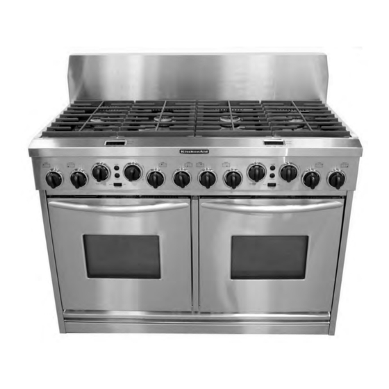
- Page 1 KAC-38 TECHNICAL EDUCATION 48″ Dual Fuel Slide-In Range Model: KDRP487MSS JOB AID 4317355...
- Page 2 FORWARD This KitchenAid Job Aid, “48″ Dual Fuel Slide-In Range,” (Part No. 4317355), provides the technician with information on the installation, operation, and service of the 48″ Dual Fuel Slide- In Range. It is to be used as a training Job Aid and Service Manual. For specific information on the model being serviced, refer to the “Use and Care Guide,”...
-
Page 3: Table Of Contents
TABLE OF CONTENTS Page GENERAL ..........................1-1 KitchenAid Model & Serial Number Designations .............. 1-1 Model & Serial Number Label And Tech Sheet Locations..........1-2 Specifications ........................1-3 KitchenAid Warranty ......................1-5 INSTALLATION INFORMATION ................... 2-1 L.P. Gas Conversion ......................2-1 Adjusting For The Proper Flame .................. - Page 4 Page COMPONENT TESTING ......................5-1 Control Power & Cavity Light Transformers ..............5-1 Blower Motor ........................5-2 Convection Bake Element ....................5-2 Oven Door Latch Assembly ....................5-3 Oven Temperature Sensor ....................5-4 Oven Shutdown Thermal Fuse ..................5-5 Convection Fan Motor ....................... 5-5 Broil Element ........................
-
Page 5: General
GENERAL KITCHENAID MODEL & SERIAL NUMBER DESIGNATIONS MODEL NUMBER MODEL NUMBER P 48 7 M SS INTERNATIONAL SALES IND. OR MARKETING CHANNEL IF PRESENT PRODUCT GROUP K = KITCHENAID PRODUCT IDENTIFICATION DD = DUAL FUEL DROP-IN / SLIDE-IN DR = DUAL FUEL RANGE... -
Page 6: Model & Serial Number Label And Tech Sheet Locations
MODEL & SERIAL NUMBER LABEL AND TECH SHEET LOCATIONS The Model/Serial Number label and Tech Sheet locations are shown below. Tech Sheet Location (Behind Control Panel) Model & Serial Number Location (On Oven Frame Behind Door) -
Page 7: Specifications
SPECIFICATIONS Model Number KDRP487MSS Dimensions/Specifications Weight Ratings Pigtail Required Electric Voltage/Phase/Frequency(Hz) 240/208V, Single, 60 Hz Total Connected Load In Kw 240 V Recommended Circuit Amps 50 Amp Exterior Cabinet Finish Stainless Control Panel Color Brushed Chrome Control Knob Material Heavy Duty, Plastic... - Page 8 Model Number KDRP487MSS Interior Main Oven (Both Ovens) Cooking System True Convection Cleaning System Self Cleaning Auto Self Clean Latch Main Oven Dimensions Main Oven Volume (cu ft) 3.25; Usable: 2.86 Main Oven Height (in) 16" Main Oven Width (in) 19"...
-
Page 9: Kitchenaid Warranty
For one year from the date of purchase, when this appliance is operated and maintained according to instructions attached to or furnished with the product, KitchenAid will pay for factory specified parts and repair labor costs to correct defects in materials or workmanship. Service must be provided by a KitchenAid-designated service com- pany. - Page 10 — NOTES —...
-
Page 11: Installation Information
INSTALLATION INFORMATION L.P. GAS CONVERSION To convert the cooktop burners for use WARNING with L.P. gas: a) Remove the grates and burner caps. Electrical Shock Hazard b) Remove the two T-20 torx screws from Disconnect power before each of the burner heads and remove servicing. - Page 12 c) Use an 8 mm socket and carefully re- e) Place the natural gas orifices in the ori- move the orifice spud from each of the fice card holes. four burners. To convert the gas distribution valve for use with L.P. gas: NOTE: The gas distribution valve on your Surface unit may look different than the one shown...
- Page 13 c) Unscrew the conversion cap from the d) Install the loop on the plastic cap over gas distribution valve and remove it and the natural gas side of the conversion the plastic cap. Note the difference be- cap. tween the L.P. and Natural gas ends of e) Install the plastic cap and the conver- the cap.
-
Page 14: Adjusting For The Proper Flame
ADJUSTING FOR THE PROPER FLAME COOKTOP BURNERS c) Hold the gas valve stem with a pair of pliers, and turn the screw in either di- Turn on one of the surface burners and set rection until the flame size is approxi- the flame to its lowest (LOW) setting. -
Page 15: Installing The Anti-Tip Bracket
INSTALLING THE ANTI-TIP BRACKET NOTE: The anti-tip bracket can be installed to WARNING hold either the right or left rear leg of the range. Determine which leg you wish to anchor to the floor. Place the anti-tip bracket template on the floor in the range opening so that the top edge is against the wall, molding, or cabi- net, and the bracket template is in the... - Page 16 To mount the anti-tip bracket to a wood To mount the anti-tip bracket to a con- floor: crete or ceramic floor: a) Use the bracket template to mark the a) Use the bracket template to mark the hole locations to be drilled. hole locations to be drilled.
-
Page 17: Theory Of Operation
THEORY OF OPERATION ELECTRONIC OPERATION The components that control the electronic op- The two thermostat & selector switch assem- eration of this range include the following: blies are mounted on the front manifold panel, and function the same as a touch pad on a Thermostat &... - Page 18 The electronic controls have six cooking re- The main electronic control and the two elec- lays, as shown in the wiring diagram to the tronic controls (secondary boards) interconnect right, and two door latching relays that oper- wiring is shown below. ate during self-cleaning.
-
Page 19: Component Access
COMPONENT ACCESS This section instructs you on how to service each component inside the 48″ Dual Fuel Slide-In Range. The components and their locations are shown below. COMPONENT LOCATIONS Burner Base & Ignitor Oven Temperature Sensor (On Rear Panel) Suppressor Board Oven Shutdown Thermal Fuse (On Rear Panel) Blower Motor Convection Fan Motor &... -
Page 20: Removing The Cooktop, Burner Base, & Ignitor
REMOVING THE COOKTOP, BURNER BASE, & IGNITOR To remove the cooktop: WARNING a) Remove the two T-20 torx screws from each of the burner heads and remove Electrical Shock Hazard the heads from the cooktop. Disconnect power before Burner Head servicing. - Page 21 To remove a burner base and an igni- d) Remove the screw from the ignitor and tor: remove the ignitor from the burner base. e) Remove the two hex-head screws from a) Remove the gas line from the burner the burner base and remove the base base.
-
Page 22: Removing The Control Panel And Components
REMOVING THE CONTROL PANEL AND COMPONENTS To remove the control panel: WARNING a) Pull the knobs off the gas valves, selec- tor switches, and thermostats. Electrical Shock Hazard b) Remove the two indicated machine Disconnect power before screws from each bezel of the two servicing. - Page 23 d) Carefully unsnap the CANCEL and To remove a spark module: ENTER pushbutton boards for both Spark Modules ovens, and remove the coil springs. Be Left Right careful not to break the fragile holder tabs. a) Remove the control panel from the unit (see step 3 on page 4-4 for the proce- dure).
- Page 24 b) Pull the round rubber shields off the To remove a gas valve: eight gas valve shafts. a) Remove the control panel from the unit (see step 3 on page 4-4 for the proce- dure). b) Remove the ignition switch from the valve under test (see step 5 on page 4-5 for the procedure).
- Page 25 To remove a clock: e) Disconnect the 2-wire connector from the clock board. a) Remove the control panel from the unit Clock Assembly (see step 3 on page 4-4 for the proce- dure). b) Disconnect the 12-wire quick discon- nect from the thermostat & selector switch assembly.
- Page 26 d) Open both oven doors. a) Remove the control panel from the unit (see step 3 on page 4-4 for the proce- e) Remove the six screws from the vent dure). grille and remove the grille. b) Remove the front panel frame (see step 7 on page 4-7 for the procedure).
- Page 27 f) Pull the electronic control and trans- 10. To remove the left or right cavity light former platform out of the unit, remove transformer or control power trans- the three hex-head screws from the former housing, and remove the housing and a) Remove the thermostat &...
-
Page 28: Removing An Oven Door Latch Assembly & A Control Panel Thermal Fuse
REMOVING AN OVEN DOOR LATCH ASSEMBLY & A CONTROL PANEL THERMAL FUSE a) Use a 90° ratchet and remove the two WARNING screws from the oven door latch as- sembly. Electrical Shock Hazard Disconnect power before servicing. Replace all parts and panels before operating. - Page 29 To remove a control panel thermal fuse: d) Disconnect the two wires from the ends of the control panel thermal fuse. Control Panel Thermal Fuse Wire Connectors Control Panel Thermal Fuses (Behind Vent Grille) a) Remove the control panel from the unit (see step 3 on page 4-4 for the proce- dure).
-
Page 30: Removing The Main Electronic Control
REMOVING THE MAIN ELECTRONIC CONTROL Remove the three screws from each end WARNING of the bottom trim and remove the trim. Electrical Shock Hazard Disconnect power before servicing. Replace all parts and panels before operating. 3 Bottom Trim Screws Failure to do so can result in death or electrical shock. - Page 31 Disconnect the wire connectors from the Remove the screws from the main elec- main electronic control. tronic control board holder and remove the control assembly from the drawer. Main Electronic Control Wire Connectors Main Electronic Control Housing Screws 4-13...
-
Page 32: Removing A Halogen Lamp Assembly
REMOVING A HALOGEN LAMP ASSEMBLY Pull the halogen bulb out of the socket. WARNING Electrical Shock Hazard Halogen Bulb Disconnect power before servicing. Replace all parts and panels before operating. Failure to do so can result in death or electrical shock. Fire Hazard Socket Assembly Shut off gas supply line valve... -
Page 33: Removing A Broil Element
REMOVING A BROIL ELEMENT Remove the two front bracket screws and WARNING two rear bracket screws from the broil element. Electrical Shock Hazard Front Bracket Disconnect power before Screws servicing. Replace all parts and panels before operating. Failure to do so can result in Broil death or electrical shock. -
Page 34: Removing An Oven Temperature Sensor
REMOVING AN OVEN TEMPERATURE SENSOR Remove the two mounting screws from WARNING the oven temperature sensor and pull the connectors out of the mounting hole in the Electrical Shock Hazard oven liner. Disconnect power before Disconnect the sensor connector from the servicing. -
Page 35: Removing A Rear Panel
REMOVING A REAR PANEL Remove the eight screws from the rear WARNING panel and remove the panel. Electrical Shock Hazard Disconnect power before servicing. 1 of 8 Screws Replace all parts and panels before operating. Failure to do so can result in death or electrical shock. -
Page 36: Removing A Convection Bake Element & Fan Motor Assembly
REMOVING A CONVECTION BAKE ELEMENT & FAN MOTOR ASSEMBLY To remove a convection bake element: WARNING a) Remove the two screws from the con- vection bake element. Electrical Shock Hazard b) Pull it forward so you can access the Disconnect power before terminals. - Page 37 To remove a convection fan motor: f) Remove the two convection fan motor mounting screws and remove the mo- a) If not already done, remove the con- tor from the rear of the range. vection cover and the convection bake element from the rear of the oven liner (see page 4-18 for the procedure).
-
Page 38: Removing A Blower Motor Assembly
REMOVING A BLOWER MOTOR ASSEMBLY Remove the four screws from the blower WARNING motor assembly cover and remove the cover from the range. Electrical Shock Hazard Blower Motor Assembly Disconnect power before Cover Screws servicing. Replace all parts and panels before operating. -
Page 39: Removing The Suppressor Board
REMOVING THE SUPPRESSOR BOARD Suppressor Board WARNING Electrical Shock Hazard Disconnect power before servicing. Replace all parts and panels before operating. Failure to do so can result in Remove the two screws from the suppres- death or electrical shock. sor board. Fire Hazard Disconnect the wires from the terminals Shut off gas supply line valve... -
Page 40: Removing An Oven Shutdown Thermal Fuse
REMOVING AN OVEN SHUTDOWN THERMAL FUSE Remove the two screws from the oven WARNING shutdown thermal fuse and remove the fuse from the rear of the range. Electrical Shock Hazard Disconnect the wires from the thermal Disconnect power before fuse terminals. servicing. -
Page 41: Removing A Hidden Bake Element
REMOVING A HIDDEN BAKE ELEMENT Bend the cover flanges down as far as WARNING they will go. Bend Both Cover Flanges Down Electrical Shock Hazard Disconnect power before servicing. Replace all parts and panels before operating. Failure to do so can result in death or electrical shock. - Page 42 Carefully pull the hidden bake element and its mounting bracket out of the range. Pull Out Hidden Bake Element 4-24...
-
Page 43: Removing The Gas Distribution Valve
REMOVING THE GAS DISTRIBUTION VALVE WARNING Electrical Shock Hazard Disconnect power before servicing. Replace all parts and panels before operating. Failure to do so can result in death or electrical shock. Fire Hazard Shut off gas supply line valve before servicing. Check all gas line connections and replace all parts and panels before operating. -
Page 44: Removing An Oven Door
REMOVING AN OVEN DOOR CAUTION: Do not lift the oven door by its To reinstall an oven door: handle. Grasp the sides of the door and tilt it back To remove an oven door: at a slight angle, then insert the hinge hangers into the hinge slots as far as they Open the oven door to its fully open posi- will go. -
Page 45: Removing The Oven Door Glass, Hinges, & Handle
REMOVING THE OVEN DOOR GLASS, HINGES, & HANDLE Remove the oven door from the range To remove the center door glass, re- (see page 4-26 for the procedure). move the bottom bracket, (it is loose), and slide the two top corners of the glass out of Place the oven door on a padded work the door liner slots. - Page 46 d) Remove the insulation and the inner To remove the door handle, remove the door glass. two door handle screws from the bracket. Door Handle Bracket & Screws (2 each) Inner Door Glass Insulation 4-28...
-
Page 47: Removing The Oven Door Gasket
REMOVING THE OVEN DOOR GASKET Open the oven door to its fully open posi- Pull the ends of the gasket out of the liner tion. holes. Remove the screw from the door gasket bracket and remove the bracket from the Gasket Clip range. - Page 48 — NOTES — 4-30...
-
Page 49: Component Testing
COMPONENT TESTING Before testing any of the components, perform • Check all connections before replacing com- the following checks: ponents, looking for broken or loose wires, failed terminals, or wires not pressed into • The most common cause for control failure is connectors far enough. -
Page 50: Blower Motor
WARNING Electrical Shock Hazard Disconnect power before servicing. Replace all parts and panels before operating. Failure to do so can result in death or electrical shock. CONVECTION BAKE ELEMENT BLOWER MOTOR Refer to page 4-18 for the procedure for ser- Refer to page 4-20 for the procedure for ser- vicing the convection bake element. -
Page 51: Oven Door Latch Assembly
WARNING Electrical Shock Hazard Disconnect power before servicing. Replace all parts and panels before operating. Failure to do so can result in death or electrical shock. OVEN DOOR LATCH ASSEMBLY Refer to page 4-10 for the procedure for ser- vicing the oven door latch assembly. Motor Turn off gas supply and disconnect power to the range. -
Page 52: Oven Temperature Sensor
WARNING Electrical Shock Hazard Disconnect power before servicing. Replace all parts and panels before operating. Failure to do so can result in death or electrical shock. OVEN TEMPERATURE SENSOR Oven Refer to page 4-16 for the procedure for ser- Temperature Sensor vicing the oven temperature sensor. -
Page 53: Oven Shutdown Thermal Fuse
WARNING Electrical Shock Hazard Disconnect power before servicing. Replace all parts and panels before operating. Failure to do so can result in death or electrical shock. OVEN SHUTDOWN THERMAL FUSE CONVECTION FAN MOTOR Refer to page 4-22 for the procedure for ser- Refer to page 4-18 for the procedure for ser- vicing the oven shutdown thermal fuse. -
Page 54: Broil Element
WARNING Electrical Shock Hazard Disconnect power before servicing. Replace all parts and panels before operating. Failure to do so can result in death or electrical shock. BROIL ELEMENT HIDDEN BAKE ELEMENT Refer to page 4-15 for the procedure for ser- Refer to page 4-23 for the procedure for ser- vicing a broil element. -
Page 55: Ignition Switches
WARNING Electrical Shock Hazard Disconnect power before servicing. Replace all parts and panels before operating. Failure to do so can result in death or electrical shock. IGNITION SWITCHES Refer to page 4-5 for the procedure for servic- ing the ignition switches. NOTE: The ignition switches will be serviced as a complete assembly. - Page 56 — NOTES —...
-
Page 57: Diagnosis & Troubleshooting
DIAGNOSIS & TROUBLESHOOTING DIAGNOSIS • All diagnoses of this range must begin with a • All units that have failed during the first few normal check of the line voltage, blown fuses, days of use should be checked for loose and failed components. -
Page 58: Control Panel Tests
CONTROL PANEL TESTS FRONT/REAR COMPONENTS CHECK POINTS RESULTS SERVICEABLE Door Open = Open Circuit Door Switch Front P7-1 (BRN) to P7-3 (TAN) Door Closed = Closed Circuit 2450 Ω @ 21°C (70°F) Door Lock Motor (with Door Closed) Front P8-4 (ORG) to Neutral (WH) With the Oven Door Closed 1080 Ω... -
Page 59: Relay Logic
RELAY LOGIC (FOR BOTH ELECTRONIC SECONDARY CONTROLS) MODES RESET BAKE PREHEAT BAKE BROIL PREHEAT BROIL CONV. BAKE-PREHEAT CONV. BAKE CONV. BROIL-PREHEAT CONV. BROIL CONV. ROAST-PREHEAT CONV. ROAST BREAD-PREHEAT BREAD BAKING PROOF KEEP WARM CLEAN RELAY LOGIC KEY CYCLING (MAX. PERIOD = 60 SEC.) ON OR OFF NOTE: DURING THE SELF CLEAN FUNCTION, THE OTHER OVEN CANNOT OPERATE. - Page 60 — NOTES —...
-
Page 61: Wiring Diagram & Strip Circuits
WIRING DIAGRAM & STRIP CIRCUITS WIRING DIAGRAM CONTROL PANEL ELECTRONIC CONTROL THERMAL FUSE - 183°F (84°C) P9-1 P3-1 RIGHT SECONDARY P3-2 P9-3 CONTROL POWER P8-1 TRANSFORMER DOOR LOCK P3-3 P8-2 DOUBLE LINE MOTOR LATCH P8-3 BREAK RELAY P8-4 BROIL-3000W P5-1 P7-4 OVEN TEMP SENSOR... -
Page 62: Strip Circuits
STRIP CIRCUITS PREHEAT BAKE / BAKE DOUBLE LINE BREAK RELAY P4-1 OVEN BROIL-3000W P5-1 SHUTDOWN THERMAL FUSE P4-2 BAKE-2000W P5-3 P1-1 BLOWER LIGHT POWER SUPPLY P1-5 AUTO LIGHT HALOGEN SWITCH 5W/BULB PREHEAT BROIL / BROIL DOUBLE LINE BREAK RELAY P4-1 OVEN SHUTDOWN THERMAL FUSE P4-2... - Page 63 PREHEAT CONVECTION BAKE / CONVECTION BAKE DOUBLE LINE BREAK RELAY P4-1 OVEN BROIL-3000W P5-1 SHUTDOWN THERMAL FUSE P4-2 CONV-1600W P5-4 BLOWER P1-1 CONV FAN P1-3 LIGHT POWER SUPPLY P1-5 AUTO LIGHT HALOGEN SWITCH 5W/BULB PROOF DOUBLE LINE BREAK RELAY OVEN SHUTDOWN THERMAL FUSE BROIL-3000W...
-
Page 64: Keep Warm
KEEP WARM DOUBLE LINE BREAK RELAY OVEN BROIL-3000W P5-1 SHUTDOWN THERMAL FUSE BAKE-2000W P5-3 P4-1 P4-2 LIGHT POWER SUPPLY P1-5 AUTO LIGHT SWITCH HALOGEN 5W/BULB PREHEAT CONVECTION BROIL / CONVECTION BROIL DOUBLE LINE P4-1 BREAK RELAY OVEN SHUTDOWN THERMAL FUSE P4-2 BROIL-3000W P5-1... - Page 65 — NOTES —...
- Page 66 — NOTES —...
-
Page 67: Product Specifications
WARRANTY INFORMATION SOURCES IN THE UNITED STATES: FOR PRODUCT SPECIFICATIONS AND WARRANTY INFORMATION CALL: FOR WHIRLPOOL PRODUCTS: 1-800-253-1301 FOR KITCHENAID PRODUCTS: 1-800-422-1230 FOR ROPER PRODUCTS: 1-800-447-6737 FOR TECHNICAL ASSISTANCE WHILE AT THE CUSTOMER’S HOME CALL: THE TECHNICAL ASSISTANCE LINE: 1-800-253-2870...