Alcatel-Lucent 7210 SAS-T Installation Manual
Service access switch
Hide thumbs
Also See for 7210 SAS-T:
- Configuration manual (347 pages) ,
- Interface configuration manual (347 pages) ,
- User manual (321 pages)

Related Manuals for Alcatel-Lucent 7210 SAS-T


Summary of Contents for Alcatel-Lucent 7210 SAS-T
- Page 1 7210 SAS-T NSTALLATION UIDE August 2013 Document Part Number: 93-0475-01-01 *93-0475-01-01*...
- Page 2 Copyright 2013 Alcatel-Lucent All rights reserved. No portion of this document may be reproduced in any form or means without prior written permission from Alcatel-Lucent. Information in this document is proprietary and confidential to Alcatel. The information in this document is subject to change. All trademarks and registered trademarks are the property of the respective owners.
-
Page 3: Table Of Contents
7210 SAS-T Introduction and Features ........ - Page 4 Booting a 7210 SAS-T from the External Compact Flash ....... .
- Page 5 7210 SAS-T (Non-ETR Variant) Front Panel Features ....... . .9...
- Page 6 List of Tables Page 6 7750 SR-12...
- Page 7 7210 SAS-T (Non-ETR Variant) Front Panel ........
- Page 8 List of Figures Page 8 7210 SAS-T Installation Guide...
-
Page 9: Preface
® Alcatel-Lucent 7210 SAS-T and instructions to install and configure the TiMOS software. Each 7210 SAS-T router is shipped with rack-mounting brackets, a console cable, power cord (AC only), and rubber feet. Warnings and Notes Observe the warnings and notes to avoid injury or router damage during installation and maintenance. -
Page 10: Table 1: Information Symbols
Class 1 Laser Product Technical Support If you purchased a service agreement for your 7210 SAS-T and related products from a distributor or authorized reseller, contact the technical support staff for that distributor or reseller for assistance. If you purchased an Alcatel-Lucent service agreement, contact technical assistance at: http://www.alcatel-lucent.com/wps/portal/support... -
Page 11: 7210 Sas-T Overview
7210 SAS-T Overview This chapter describes the 7210 SAS-T features and includes the following sections: • 7210 SAS-T Introduction and Features on page 4 • Switch Architecture on page 6 • Features on page 7 • Hardware Description on page 9... -
Page 12: 7210 Sas-T Introduction And Features
10 10/100/1000 Copper SFP ports and 4 XFP-based 10 Gig ports • 7210 SAS-T (ETR) with support for up to 12 100/1000 fiber-optic SFP ports, 6 10/100/ 1000 Copper SFP ports, 4 XFP based 10 Gig ports and 4 Power over Ethernet (PoE) ports –A... -
Page 13: 7210 Sas-T Overview
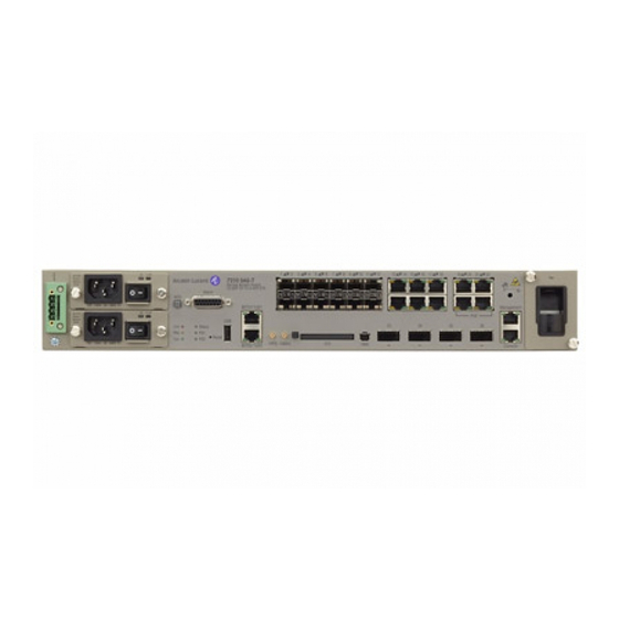
BITS2/ToD2 SAS_T_002 Figure 2: 7210 SAS-T (ETR Variant) Front Panel The 7210 SAS-T (ETR variant) include the following features: • 12 100/1000 fiber-optic SFP ports • 10 10/100/1000 Base-T fixed Copper ports • Four PoE Copper ports (out of the total 10 copper port) •... -
Page 14: Switch Architecture
Switch Architecture Switch Architecture The 7210 SAS-T employs a wire-speed, non-blocking switching fabric. This permits simultaneous wire-speed transport of multiple packets at low latency on all ports. Network Management Options This switch contains a comprehensive array of LEDs for at-a-glance monitoring of network and port status. -
Page 15: Features
7210 SAS-T Overview Features The 7210 SAS-T includes the following features: • All connections front facing • Wire speed, non-blocking, service-aware layer-2 switch • 12 100/1000 fiber-optic SFP ports • 10 10/100/1000 Base-T fixed Copper ports • Four PoE Copper SFP ports (out of the 10 Copper ports) •... -
Page 16: Onnectivity
Sync E & 1588 support • 7210 SAS-T has an operating range of 0 Celsius to 40 Celsius • 7210 SAS-T ETR variant has an environmental rating of -40 to +65 degree C operation Connectivity The 7210 SAS-T includes the following connectivity features: •... -
Page 17: Hardware Description
Status Reset 1PPS 10MHz BITS2/ToD2 SAS_T_012 Figure 3: 7210 SAS-T (Non-ETR Variant) Front Panel Table 2: 7210 SAS-T (Non-ETR Variant) Front Panel Features Description Ground and DC power connection Power trays LEDs Alarm connector USB port Alarm cut off button... -
Page 18: Table 3: 7210 Sas-T (Etr Variant) Front Panel Features
Hardware Description Table 2: 7210 SAS-T (Non-ETR Variant) Front Panel Features Description BITS timing ports (reserved for future use) OMC (Optical Management Console) port (reserved for future use) 1PPS timing output and 10 Mhz timing output (reserved for future use) - Page 19 7210 SAS-T Overview Table 3: 7210 SAS-T (ETR Variant) Front Panel Features Description USB port Alarm cut off button Reset button External Compact Flash memory card slot (cf2:\) 100/1000 fiber-optic SFP ports Management port Console port Fan tray BITS timing ports (reserved for future use)
-
Page 20: Ethernet Interfaces
Hardware Description Ethernet Interfaces The 7210 SAS-T provides 12 100/1000 fiber-optic SFP ports. Each port can be used for a direct connection to a subscriber’s Customer Premises Equipment (CPE), or as an uplink to another aggregation node. The 7210 SAS-T supports 10/100/1000 Base-T copper SFPs. The 7210 SAS-T also provides ten 10/100/1000 Base-T fixed Copper ports. -
Page 21: Console Port
The serial port configuration requirements are as follows: • Default Baud rate – 115200 bps • Character Size – 8 Characters • Parity – None • Stop bit – One • Data bits – 8 • Flow control – none 7210 SAS-T Installation Guide Page 13... -
Page 22: Larm Interface Port
Normally closed contact will be disconnected from the common contact during a Major alarm state. +24 VDC source 100 mA Available as a source voltage for use with referenced to chassis Alarm In 1-4. ground Page 14 7210 SAS-T Installation Guide... - Page 23 Alarm-In 1-4 its negative rail must not be connected to chassis ground and it should be 18-50 volts DC at 100 mA. Please refer to Appendix , “Appendix C: Alarm Pin Assignments,” on page 87 for further information. 7210 SAS-T Installation Guide Page 15...
-
Page 24: Power Modules
Hardware Description Power Modules the 7210 SAS-T chassis provides three power module options: -48V, +24V and universal AC. See Figure 5 for an illustration of the power modules. For specifications on the power supply modules and external input power requirements, see "Connecting to a Power Source"... - Page 25 The -48V/+24V/AC LEDs on the left indicate the status of external power. The +12V LED on the right indicates the status of the internal power conversion process. You must use AC and/or DC power supplies with your 7210 SAS-T. AC and DC power Note: supplies can be used simultaneously.
-
Page 26: Dc Power Source Failure Detection
PS2 input failure / PS2 output OK Failed Available PS1 input failure / PS1 output OK Failed Failed No power to system Available Available None Available Failed None PS2 input failure / PS2 output OK Page 18 7210 SAS-T Installation Guide... - Page 27 PS2 input failure / PS2 output failure Available Available Available Failed Input failure / Not detected Failed Available PS1 input failure / PS1 output OK Failed Failed PS1 input failure / PS1 output OK 7210 SAS-T Installation Guide Page 19...
-
Page 28: Usb Port
TiMos images. It can also be used to boot the system, as described in Booting a 7210 SAS-T from the External Compact Flash on page 54. Please refer to the 7210 SAS- T release notes for detailed information on the supported Compact Flash storage devices supported on the 7210 SAS-T system. -
Page 29: Fan Tray
The fan tray also contains an air filter. The filter tray must always be installed while the chassis is powered up. The air filter prevents large particles, debris, and dust from entering and circulating through the system. Inspect your air filter monthly and clean it when accumulated dust is present. 7210 SAS-T Installation Guide Page 21... -
Page 30: Figure 7: Loosening Captive Screws On The Fan Tray
Hardware Description To inspect and remove your air filter, perform the following steps: Loosen the captive screws on the fan tray. Step 1 SAS_T_021 Figure 7: Loosening Captive Screws on the Fan Tray Page 22 7210 SAS-T Installation Guide... -
Page 31: Figure 8: Removing The Fan Tray
7210 SAS-T Overview Step 2 Carefully remove the fan tray from the router chassis and remove the air filter to inspect it and clean it if necessary. SAS_T_022 Figure 8: Removing the Fan Tray 7210 SAS-T Installation Guide Page 23... -
Page 32: Figure 9: Replacing The Fan Tray
After inspecting and cleaning the air filter, replace it in the fan tray so that the edge of the air filter is flush with the rear of the fan tray. SAS_T_023 Figure 9: Replacing the Fan Tray Page 24 7210 SAS-T Installation Guide... -
Page 33: Figure 10: Tightening Captive Screws On The Fan Tray
7210 SAS-T Overview Step 4 Replace the fan tray and tighten the captive screws. SAS_T_024 Figure 10: Tightening Captive Screws on the Fan Tray 7210 SAS-T Installation Guide Page 25... -
Page 34: System Leds And Buttons
Crit Status Reset 1PPS 10MHz BITS2/ToD2 SAS_T_009 Figure 11: System LEDs and Buttons Table 7: 7210 SAS-T System LEDs and Buttons Description Power tray LED Power tray switch Alarm cut off button Alarm LED Power status LED Reset button BITS port LED... - Page 35 7210 SAS-T Overview Table 7: 7210 SAS-T System LEDs and Buttons Description Console port LED. Note: Only the LED on the right side of the port is operational. The LED on the left side of the port is not used.
-
Page 36: System And Port Leds
Port has a valid link. Flashing Green Flashing indicates activity on the port. The link is down. Base-T fixed Copper ports Green Port has a valid link. 13–22 (right-side LED) Flashing Green Flashing indicates activity on the port. Page 28 7210 SAS-T Installation Guide... -
Page 37: Table 10: Port Led Key Descriptions
LED that indicates status for an odd-numbered port. Odd-numbered ports are in the top row. Reserved. LED that indicates status for an even numbered port. Even-numbered ports are in the bottom row. SFP slots. 7210 SAS-T Installation Guide Page 29... -
Page 38: System Buttons And Switches
Standby mode if switch is connected to a power source. AC or DC power is applied to the switch. ACO (Alarm Cut Off) Not pushed Normal operating mode. Reset (Recessed) Not pushed Normal operating mode. Push to reset hardware. Page 30 7210 SAS-T Installation Guide... -
Page 39: Installing The 7210 Sas-T
Installing the 7210 SAS-T This chapter describes site preparation and installation of your 7210 SAS-T and includes the following sections: • Site Preparation on page 32 • Installing Your Switch on page 34 7210 SAS-T Installation Guide Page 31... -
Page 40: Site Preparation
Selecting a Site Mount the 7210 SAS-T in a standard 19-inch equipment rack or on a flat surface. When you mount your switch on a flat surface, ensure that the four rubber feet are installed on the bottom of the box. -
Page 41: Equipment Checklist
Installing the 7210 SAS-T Equipment Checklist After unpacking your switch, check the contents to make sure all the components are present. Before installation, make sure you have all the necessary equipment. 7210 SAS-T Installation Guide Page 33... -
Page 42: Ack Mounting
M a n a P O E g e m e SAS T 017 Figure 13: Attaching the Brackets Step 2 Mount the 7210 SAS-T in the rack, using four rack-mounting screws (not provided). See Figure Page 34 7210 SAS-T Installation Guide... -
Page 43: Figure 14: Nstalling The Switch In A Rack
Installing the 7210 SAS-T F a n M a n a P O E g e m e SAS_T_018 Figure 14: Installing the Switch in a Rack If you are installing a single switch, proceed to Grounding the Chassis on page... -
Page 44: Desktop Or Shelf Mounting
"Grounding the Chassis" on page Step 3 If you are installing multiple switches, attach four adhesive feet to each switch. Place each Step 4 device squarely on top of the one below, in any order. Page 36 7210 SAS-T Installation Guide... -
Page 45: Grounding The Chassis
Installing the 7210 SAS-T Grounding the Chassis The router is suitable for installation as part of the Common Bonding Network (CBN) or an Isolated Bonding Network (IBN). The router is suitable for installation in Network Telecommunication Facilities or locations where the NEC applies. - Page 46 An external circuit breaker no greater than 15A must be located within a readily Danger: accessible distance of the equipment. This is intended as the disconnect device. Page 38 7210 SAS-T Installation Guide...
-
Page 47: Onnecting To A Power Source
Notes: accepts a single AC and single DC power supply. Notes: The 7210 SAS-T ETR variant must use the extended temperature range power supplies. Connecting to AC Power Notes: In order to comply with the GR-1089 Lightning Criteria for Equipment Interfacing With AC Power Ports, an external Surge Protective Device (Perma Power Model # PXD309) is intended to be used at the AC input of the router. -
Page 48: Connecting To Dc Power
Installing Your Switch Ensure that PS1 and PS2 LEDs on the 7210 SAS-T front panel are lit if both the primary Step 6 and the redundant power supply has been plugged in. If only one of the power supplies is plugged in, either PS1 or PS2 will be lit. PS1 will... -
Page 49: Figure 16: Connecting To A -48 Vdc Power Source
Installing the 7210 SAS-T The wiring between the DC power supply and the switch must be stranded copper wire Step 3 within the range of 16 to 20 AWG in accordance with local electrical codes. Step 4 Connect the VDC power feed using the VDC input and RETA/B (return) lines for power source A and B, respectively. -
Page 50: Figure 17: Connecting To A +24 Vdc Power Source
If you have installed both a primary and redundant power supply module, verify that the Step 7 LEDs on both modules are lit as indicated in the preceding step. Page 42 7210 SAS-T Installation Guide... -
Page 51: Connecting To The Console Port
Installing the 7210 SAS-T Ensure that PS1 and PS2 LEDs on the 7210 SAS-T front panel are lit if both the primary Step 8 and the redundant power supply has been plugged in. If only one of the power supplies is plugged in, either PS1 or PS2 will be lit. PS1 will... - Page 52 Installing Your Switch Page 44 7210 SAS-T Installation Guide...
-
Page 53: In This Chapter
MDA ports that support these devices. • Warnings and Notes on page 46 • Installation Preparation on page 47 • Locking Mechanisms on page 47 • Installing SFP/XFPs on page 48 • Removing SFP/XFPs on page 48 7210 SAS-T Installation Guide Page 45... -
Page 54: Warnings And Notes
• Do not remove the dust cover on the connector until you are ready to install the SFP. Always replace the the dust cover when the SFP is removed. Notes: • Discard SFPs according to all local laws and regulations. • SFPs are keyed to prevent incorrect insertion. Page 46 7210 SAS-T Installation Guide... -
Page 55: Installation Preparation
Blow dry the ferrule with compressed air and inspect for lint. Do not insert the compressed air nozzle into the receptacle when blowing out. Locking Mechanisms Alcatel-Lucent SFP/XFPs can use different lock and release methods. Possible lock and release mechanisms include: •... -
Page 56: Installing Sfp/Xfps
Step 4 Connect the network cable or place a safety cap over the optical transceiver. Step 5 Verify that the temperature ratings for the SFPs and XFPs match those of the intended Note: operating environment. Page 48 7210 SAS-T Installation Guide... -
Page 57: Configuring The 7210 Sas-T
Configuring the 7210 SAS-T This chapter describes how to configure your 7210 SAS-T and contains the following sections: • Diagnostics on page 50 • Initializing the System and Downloading Software on page 51 • Establishing Router Connections on page 70... -
Page 58: Diagnostics
PS1: Steady Green (if Power supply in the top slot is inserted) OR PS2: Steady Green (if Power supply in the bottom slot is inserted). If any of the above LEDs shows a different state, press the Reset button and wait for a few seconds to let the system boot. Page 50 7210 SAS-T Installation Guide... -
Page 59: Initializing The System And Downloading Software
Timos available in the flash. Booting a 7210 SAS-T in the Lab There are several ways to boot the 7210 SAS-T from the network. User can choose to boot the device using one of the following options: •... - Page 60 Contents of Boot Options File on uf1: primary-image uf1:/both.tim #eth-mgmt Port Settings: eth-mgmt-disabled eth-mgmt-address 10.135.20.127/24 active eth-mgmt-route 10.0.0.0/8 next-hop 10.135.20.1 eth-mgmt-autoneg eth-mgmt-duplex full eth-mgmt-speed #uplinkA Port Settings: uplinkA-port 1/1/26 uplinkA-address uplinkA-vlan uplinkA-route #uplinkB Port Settings: uplinkB-port 1/1/24 uplinkB-address uplinkB-vlan uplinkB-route Page 52 7210 SAS-T Installation Guide...
- Page 61 Configuring the 7210 SAS-T #System Settings: wait persist console-speed 115200 console-disabled Hit a key within 1 second to change boot parameters... Configuring Network with eth-mgmt Port Setting..No existing config file URL Primary image location: uf1:/both.tim Initial DNS resolving preference is ipv4-only Loading image uf1:/both.tim...
-
Page 62: Booting A 7210 Sas-T From The External Compact Flash
Booting a 7210 SAS-T from the External Compact Flash User can boot the 7210 SAS-T using the external compact flash device slot on the front panel using one of the recommended compact flash devices. User needs to first format the compact flash, using a Windows PC and compact flash read/write device, as a DOS file system (as a FAT32 or FAT16 file system) and then copy over the Timos images boot.tim and both.tim into the compact flash... - Page 63 Configuring the 7210 SAS-T Contents of Boot Options File on cf2: primary-image cf2:/both.tim #eth-mgmt Port Settings: eth-mgmt-disabled eth-mgmt-address 10.135.20.127/24 active eth-mgmt-route 10.0.0.0/8 next-hop 10.135.20.1 eth-mgmt-autoneg eth-mgmt-duplex full eth-mgmt-speed #uplinkA Port Settings: uplinkA-port 1/1/26 uplinkA-address uplinkA-vlan uplinkA-route #uplinkB Port Settings: uplinkB-port...
- Page 64 TiMOS-B-0.0.I1810 both/hops ALCATEL SAS-T 12F10T 4XFP ETR 7210 Copyright (c) 2000-2013 Alcatel-Lucent. All rights reserved. All use subject to applicable license agreements. Built on Fri Aug 16 21:44:24 IST 2013 by builder in /home/builder/0.0/p Page 56 7210 SAS-T Installation Guide...
-
Page 65: Booting A 7210 Sas-T Using The Image On Flash (With The Image Shipped By Factory)
Configuring the 7210 SAS-T Booting a 7210 SAS-T using the image on Flash (with the image shipped by factory) You will need the following: • A PC with a serial port and Hyperterminal • Cable that connects the console port of SAS-T to the serial port of PC Connect the 7210's console port to serial port of the PC and then power on the 7210. - Page 66 Enter the location of the configuration file. Or none since you are booting for the first time. You can skip all the remaining prompt that appear on the screen by pressing ‘ENTER’ until to get to the following prompt Page 58 7210 SAS-T Installation Guide...
-
Page 67: Booting A 7210 Sas-T From The Network
Booting a 7210 SAS-T From the Network There are several ways to boot the 7210 SAS-T from the network. User has options to use one of the front panel ports (refered to as uplinkA and uplinkB in the display output shown below) or the out-of-band ethernet management port (refered to as eth-mgmt port in the display output shown below) to boot the 7210 SAS-T from the network. -
Page 68: Figure 1: 7210 Sas-T Boot Process
• A PC with a serial port and Hyperterminal • Cable that connects the console port of 7210 SAS-T to the serial port of PC • A network cable to connect the 7210 unit to the network The following sections describe how to boot the device using either of the options listed above. -
Page 69: Default Settings
Configuring the 7210 SAS-T Relocating code...Jumping to RAM Performing second stage RAM test..passed Board Serial Number is 'SN12345678' Bootlog started for Version V-1.0.R1 Build V-1.0.R1 bootrom/mpc 7xxx Built on Thu Jan 15 14:55:59 IST 2009 by builder in /builder/ws/panos/main Since the router does not ship with a BOF, it will show the default settings. - Page 70 You will be asked to configure the port number, IP address, static routes, and VLAN Id for uplink ports. uplinkA Port Setting -------------------- Existing uplinkA port settings are: uplinkA-port 1/1/1 Page 62 7210 SAS-T Installation Guide...
- Page 71 Configuring the 7210 SAS-T uplinkA-address uplinkA-vlan uplinkA port is configured for Boot Interface Management, Press Enter to proceed with existing port settings Or "disable" to disable the port for Boot Interface Management Or "edit" to change the port settings: Type edit.
- Page 72 All rights reserved. All use subject to applicable license agreements. Built on Wed Jul 15 17:18:37 IST 2009 by builder in /builder/ws/1.1B1/sultan Login: The default username and password are admin. Use it to log into the 7210 SAS-T. Page 64 7210 SAS-T Installation Guide...
-
Page 73: Using The Out-Of-Band Ethernet Management Port To Boot 7210 From The Nework
Configuring the 7210 SAS-T The status LED will be Green when the device has successfully completed the boot process Note: and is running normally. It is highly recommended that you change the default admin password to prevent unauthorized access to the node. - Page 74 Boot Interface Management New Settings ------------ primary-image ftp://*:*@10.10.170.22/./images/both.tim #eth-mgmt Port Settings: eth-mgmt-disabled eth-mgmt-address 10.135.25.97/24 eth-mgmt-route 10.135.0.0/16 next-hop 10.135.25.1 eth-mgmt-route 135.254.0.0/16 next-hop 10.135.25.1 eth-mgmt-autoneg eth-mgmt-duplex full eth-mgmt-speed #System Settings: wait persist Page 66 7210 SAS-T Installation Guide...
- Page 75 Executing TiMOS image at 0x100000 ..After the 7210 SAS-T boots up, you should see the following prompt: All rights reserved. All use subject to applicable license agreements. Built on Tue Jul 13 23:24:58 IST 2010 by builder in /builder/2.0B1/panos/main Login: The default username and password are admin.
-
Page 76: Downloading The Timos Software To The Internal Flash
Downloading the TiMOS Software to the Internal Flash If you want to boot the 7210 SAS-T from the internal flash, you will have to copy the image there. If you have used the uplinkA or uplinkB port to boot the 7210, use any of the network ports for IP connectivity and follow the procedure given below to configure an IP interface and a route. - Page 77 Saving BOF ..Completed. A:SN12# Reboot the 7210 SAS-T. The device will pick up both the image and the configuration from the internal flash. Note: If you have used the USB storage device or the external compact flash, the images boot.tim and both.tim can be copied to the internal flash (cf1:\) by using the file copy CLI commands.
-
Page 78: Establishing Router Connections
Establish the connection by pressing the Enter key a few times on your terminal keyboard. At the router prompt, enter the login and password. Step 4 The default login is admin The default password is admin Page 70 7210 SAS-T Installation Guide... -
Page 79: Telnet Connection
*A: 7210SAS# configure system security telnet-server. Each 7210 SAS-T is limited to a total of five inbound/outbound Telnet or SSH sessions and 1 Console login to guarantee that either inbound or outbound sessions will be available. MAC addresses are listed on a small label on the chassis. The MAC address also displays in the show router arp command output. -
Page 80: Running Telnet
To establish a Telnet connection, run a Telnet program and issue the Telnet command, followed by the IP address: The following displays an example of a Telnet login: C:\>telnet 10.10.10.25 Login: admin Password: ######## ALA-1# Page 72 7210 SAS-T Installation Guide... -
Page 81: Troubleshooting
This chapter describes troubleshooting methods and procedures and includes the following sections: • Diagnosing Switch Indicators on page 74 • Power and Cooling Problems on page 76 • Installation on page 77 • In-Band Access on page 78 7210 SAS-T Installation Guide Page 73... -
Page 82: Diagnosing Switch Indicators
Critical LED is RED Critical alarm detected. • One or more critical system alarm(s) have occurred. Major LED is RED Major alarm detected. • One or more major system alarm(s) have occurred. Page 74 7210 SAS-T Installation Guide... - Page 83 • Verify that the proper cable type is used and its length does not exceed specified limits. • Check the adapter on the attached device and cable connections for possible defects. Replace the defective adapter or cable if necessary. 7210 SAS-T Installation Guide Page 75...
-
Page 84: Power And Cooling Problems
However, if the unit powers off after running for a while, check for loose power connections, power losses or surges at the power outlet, and verify that the fans on the unit are unobstructed and running prior to shutdown. Page 76 7210 SAS-T Installation Guide... -
Page 85: Installation
Verify that all system components have been properly installed. If one or more components appear to be malfunctioning (such as the power cord or network cabling), test them in an alternate environment where you are sure that all the other components are functioning properly. 7210 SAS-T Installation Guide Page 77... -
Page 86: In-Band Access
NOTE: The management agent can accept up to seven simultaneous Telnet sessions. If the maximum number of sessions already exists, an additional Telnet connection will not be able to log into the system. Page 78 7210 SAS-T Installation Guide... -
Page 87: Appendix A: Specifications
Appendix A: Specifications This appendix provides system specifications and includes the following sections: • Specifications on page 80 7210 SAS-T Installation Guide Page 79... -
Page 88: Specifications
Specifications Specifications Table 3: 7210 SAS-T Specifications Item Width Height Depth Physical dimensions Size 17.17" (43.6 cm) 2.64" (1.5RU) (6.7 cm) 9.96" (25.3 cm) Weight 11 lbs. (5 kg) Environmental Operating Temperature ETR variant: -40º C to 65º C (-49º F to 149º F) (standard) IEC 68-2- Non-ETR variant: 0º... -
Page 89: Japan Vcci Class A Declaration
Appendix A: Specifications Table 3: 7210 SAS-T Specifications (Continued) Item Width Height Depth Safety, EMC and Immunity Safety CSA/NRTL (UL60950-1, CSA 22.2.No 60950-1) Europe CE Mark: EN50081-1: EN55022 Class A EN60555-2/3 North America: FCC 47 CFR Part 15 Class A... - Page 90 Specifications Page 82 7210 SAS-T Installation Guide...
-
Page 91: Appendix B: Pin Assignments
Appendix B: Pin Assignments This appendix contains pin assignments and includes the following sections: • Management Port Pin Assignments on page 84 • Console Port Pin Assignment on page 85 7210 SAS-T Installation Guide Page 83... -
Page 92: Management Port Pin Assignments
4, 5, 7, 8 Not used Not used NOTE: • The “+” and “-” signs represent the polarity of the wires that make up each wire pair. • Auto-negotiation must be enabled for automatic MDI/MDI-X pinout configuration. Page 84 7210 SAS-T Installation Guide... -
Page 93: Console Port Pin Assignment
Used as defined. Should be connected Used as defined. Should be connected Used as defined. Should be connected Used as defined. Should be connected Not used. Should not be connected Used as defined. Should be connected 7210 SAS-T Installation Guide Page 85... - Page 94 Console Port Pin Assignment Page 86 7210 SAS-T Installation Guide...
-
Page 95: Appendix C: Alarm Pin Assignments
Appendix C: Alarm Pin Assignments This appendix contains pin assignments and includes the following sections: • Alarm Port Pin Assignments on page 88 7210 SAS-T Installation Guide Page 87... -
Page 96: Alarm Port Pin Assignments
SNMP trap. An alarm input can also be configured to drive the appropriate alarm output pin. Please refer the System Basics user guide for more details on configuring the alarm inputs. Table 6 for the alarm interface port pinouts. Page 88 7210 SAS-T Installation Guide... -
Page 97: Appendix C: Alarm Pin Assignments
Common contact for Major alarm relay. MJR_ALARM_NO Normally open contact will be connected to the common contact during a Major alarm state. ALARM_IN4_EXT_RTN External alarm input 4 (external relay dry contact closure from pin 5). 7210 SAS-T Installation Guide Page 89... - Page 98 100 mA. If an external power source is used its outputs must be isolated from chassis ground, for example do not connect the alarm power supply return to chassis or rack ground in this scenario. Please reference Figures 1-3 and the 7210SAS-T software configuration guide. Page 90 7210 SAS-T Installation Guide...
-
Page 99: Figure 3: Example For Alarm Inputs Using An External Power Source
Appendix C: Alarm Pin Assignments Figure 3: Example for Alarm Inputs Using an External Power Source 7210 SAS-T Installation Guide Page 91... -
Page 100: Figure 4: Example For Alarm Inputs Using An External Power Source
Figure 4: Example for Alarm Inputs Using an External Power Source An example of the CLI commands to setup the alarm monitoring in the 7210SAS is show below. Please reference the 7210SAS Basic System Configuration Guide. *A:M3>config>system# info ---------------------------------------------- #-------------------------------------------------- echo "System Configuration" #-------------------------------------------------- Page 92 7210 SAS-T Installation Guide... - Page 101 Last State Change : 01/24/2011 12:55:51 Alarm Input Pin Number : 4 Alarm Input Pin Description : Alarm Input Pin Current State : Disabled Alarm Output Pin Used : Major Last State Change : 01/24/2011 12:55:51 7210 SAS-T Installation Guide Page 93...
- Page 102 Alarm Port Pin Assignments Page 94 7210 SAS-T Installation Guide...