Advertisement
Quick Links
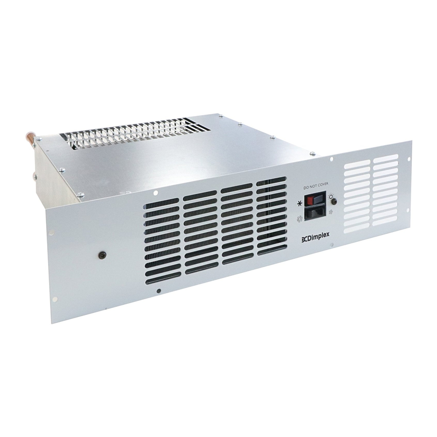
Hydronic Base Unit Heater
Model: BUH19BWS
Dimensions
(millimetres)
THESE INSTRUCTIONS SHOULD BE READ CAREFULLY AND RETAINED FOR FUTURE REFERENCE
IMPORTANT SAFETY ADVICE
When using electrical appliances, basic precautions
should always be followed to reduce the risk of fire,
electrical shock, and injury to persons, including the
following:
•
WARNING THE SURFACES OF THIS HEATER CAN BE
HOT
•
This appliance is not intended for use by children or
other persons without assistance or supervision if
their physical, sensory or mental capabilities prevent
them from using it safely. Children should be
supervised to ensure that they do not play with the
appliance.
•
If you use this heater in conjunction with an external
thermal control, a programme controller, a timer or any
other device which switches the heat on automatically,
observe all safety warnings AT ALL TIMES since a fire
risk exists when the heater is accidentally covered or
displaced.
•
The installation of this product should be carried out
by an electrician or competent person and be in strict
accordance with the current IEE Wiring Regulations
and relevant Building Regulations.
•
NEVER cover or obstruct in any way the heat outlet
slots at the front of the heater or the air inlet slots at
the top and rear of the heater.
•
DO NOT cover the heater – Do not place material or
garments on the heater or obstruct the air circulation
around the heater
•
Before connecting the heater check that the supply
voltage is the same as that stated on the heater.
•
The heater must be installed in accordance with these
instructions.
•
The heater should be installed and operated in the
horizontal position as shown in diagram above.
•
The heater should be positioned in accordance to the
clearances stated in these instructions.
•
DO NOT locate this heater immediately beneath a fixed
socket outlet.
•
This appliance must be earthed.
Installation and Operating Instructions
Depth does not
include valves
and flexible pipe
General
This heater has been designed for fitting in the space behind
the plinth of floor standing kitchen units or other fitted
furniture units. It is recommended that the heater is not
installed under cupboards used for storing perishable goods.
This heater may be fitted in place of or in addition to existing
radiators. Using the hot water from the central heating
system and a powerful electric faint will produce an average
2.0kW of heat into the room.
Installation
The heater is more easily fitted during the installation of new
furniture units, or in existing furniture units if they can be
temporarily moved from their position against the wall. If an
existing furniture unit cannot be moved, then it may be
necessary to remove the back of the unit in order to gain
access to carry out the wiring installation.
Before installing the unit consider the location with respect to
the following:
•
The product has a depth of 395mm, the length of the
valves and flexible cable should also be taken in to
consideration.
•
The electrical supply and cable length.
•
Position of system pipework and flexible hose length.
•
Position the heater to deliver heat effectively without
causing personal discomfort from overheating while
standing at work surfaces etc.
•
If the overhang above the heater is greater than 75mm,
then a distance of at least 100mm must be maintained
between the overhang and the uppermost part of the
heater (see Fig. 1 below).
08/18304/2
(30/04/09)
Issue 2
Ensure
air inlet
grille is
clear
Fig. 1
Advertisement

Related Manuals for Dimplex BUH19BWS


Summary of Contents for Dimplex BUH19BWS
- Page 1 Installation and Operating Instructions Hydronic Base Unit Heater 08/18304/2 (30/04/09) Issue 2 Model: BUH19BWS Dimensions (millimetres) Depth does not include valves and flexible pipe Ensure air inlet grille is clear THESE INSTRUCTIONS SHOULD BE READ CAREFULLY AND RETAINED FOR FUTURE REFERENCE...
- Page 2 Fill and vent the system and bleed the air out of the heat. Central heating design system exchanger using the bleed screw provided (located at the top of the flow pipe).(see Fig. 4). When fitting the appliance onto a central heating system check that the boiler is capable of delivering extra heat into the appliance by resizing the system.
- Page 3 Marking the fixing positions Troubleshooting Slide the heater in to position in the plinth aperture with the Insufficient heat output from the heat exchanger may be front edge just behind the line of the plinth. caused by: • Airlock in the heat exchanger – (ISOLATE FROM Note: Ensure that flexible pipes are not kinked and that the ELECTRICAL SUPPLY) electrical cord is not in contact with hot surfaces.
- Page 4 Republic of Ireland Tel. 01 8424833 Hampshire. SO30 2DF [c] GDC Group Ltd. All rights reserved. Material contained in this publication may not be reproduced in whole or in part, without prior permission in writing of Dimplex. A division of GDC Group Ltd.