Table of Contents
Advertisement
INSTRUCTION MANUAL
Installation and Operating
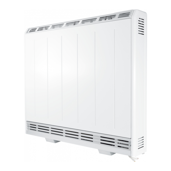
Dimplex XLE Series Heater
Models: XLE050 / XLE070 / XLE100 / XLE125 / XLE150
These instructions should be read carefully
and retained for future use. Note also the
information presented on the appliance.
08/80271/0
ISSUE: 1 Series: A
Software Version UI/CC: 52/17
Advertisement
Table of Contents

Related Manuals for Dimplex XLE050


Summary of Contents for Dimplex XLE050
- Page 1 INSTRUCTION MANUAL Installation and Operating Dimplex XLE Series Heater Models: XLE050 / XLE070 / XLE100 / XLE125 / XLE150 These instructions should be read carefully and retained for future use. Note also the information presented on the appliance. 08/80271/0 ISSUE: 1 Series: A...
- Page 2 IMPORTANT THESE INSTRUCTIONS SHOULD BE READ CAREFULLY AND RETAINED FOR FUTURE REFERENCE. Note also the information presented on the appliance CAUTION FAILURE TO FOLLOW THESE INSTRUCTIONS MAY CAUSE INJURY AND/OR DAMAGE AND MAY INVALIDATE YOUR GUARANTEE IMPORTANT SAFETY ADVICE When using electrical heaters, basic precautions should always be followed to reduce the risk of fi...
- Page 3 CAUTION: Do not use if either of the heater’s mains power leads become damaged. If the supply cord is damaged it must be replaced by the installer or an approved Dimplex service partner. Curtains must not come to within 250mm of the top of the heater.
- Page 4 CHILD SAFETY WARNING - Fixing kit screws are a potential choking hazard. WARNING - This appliance is not intended for use by persons (including children) with reduced physical, sensory or mental capabilities, or lack of experience and knowledge, unless they have been given supervision or instruction concerning use of appliance by a person responsible for their safety.
- Page 5 3.3V coin cell battery to backup real time clock. Battery life > 5 years. Supply (each) 1PN 230-240V / 50Hz (Peak / Off Peak) IP Rating IPX4 Approvals CE & BEAB Warranty 2 Years Country of Origin United Kingdom Manufacturer GDC Group Ltd. Trading as Glen Dimplex Heating & Ventilation...
- Page 6 3. Ensure the heater is stable before removing the screws which hold Models XLE050 XLE070 XLE100 XLE125 XLE150 the bottom grille panel in position. Feet Position 1 ‘A/B’ 167/124 167/185 167/246 160/314 160/375 (Fig.
- Page 7 Fig. 2 Fig. 3 Ensure the back of the heater is fl ush against the wall. If the skirting board is taller than 120mm and deeper than 15mm it should be cut to accommodate safe installation of the heater. Do not place objects within 300mm of the front of the heater and 150mm (min.
- Page 8 Installing the Heater IMPORTANT Head of wall fi xing screw must be fl anged pan head type and have a diameter no less than 11mm. No countersunk headed screws to be used for wall fi xing. The heater must be securely fi xed to a wall. Screws with suitable wall fi xings for solid walls are provided.
- Page 9 6. Six fi xing positions must be selected for models XLE100, XLE125, XLE150 and at least 4 fi xing positions for models XLE050 and XLE070. Fig. 6. Common fi xing points for all heater sizes are shown in both Fig. 4 and Fig. 5.
- Page 10 Electrical Connections Warning: Before obtaining access to terminals, all supply circuits must be disconnected. 7. The heater leaves the factory confi gured to operate with two mains supplies, a 24 hour peak supply and an off peak switched supply. (Fig. 7) Storage / Fan circuit Fan Circuit = PEAK L...
- Page 11 8. The mains cable entry and terminal block will be visible on the right hand side of the unit. Insert the mains cables through the cable gland at the bottom of the heater in readiness for connection (Fig. 8). IMPORTANT - Only heat resistant ordinary polyvinyl chloride sheathed fl exible cord should be used, the following codes apply;...
- Page 12 Fig. 9 Fig. 10 Fig. 11 Fig. 12...
- Page 13 Building the Heater Core 9. Remove the inner front and insulation to gain access to the core of the heater. Lay the inner front carefully to one side to ensure it is not damaged. (Fig. 9) 10. Remove the cardboard element support and dispose of. (Fig. 10) Energy Cells The energy cells are supplied separately to the heater in packs of three.
- Page 14 Fig. 13 Fig. 14 Fig. 15 Fig. 16...
- Page 15 13. The third row of energy cells is positioned in a manner similar to the fi rst row. Again be careful not to damage or dislodge the element. (Fig. 13) 14. Fit the fourth row of energy cells above the third row in the upside position. Again, fi...
- Page 16 Operation The controls are located on the top of the heater. The heater is fi tted with an adjustable electronic controller consisting of a display screen and six touch sensitive buttons. Display Screen ‘Menu’ Button ‘Back’ Button ‘Up and Down’ Arrows ‘Enter’...
- Page 17 Control Functions The heater controls can be easily adjusted by using the six buttons on the User Interface. The Display Screen shows the options available at each stage of adjustment. Menu - displays the main options list; - Date/Time - Set the date and time. - Mode - Set the mode of operation.
- Page 18 Main Screen After 30 seconds the heater will default back to the Main Screen. Here the chosen temperature is displayed along with the mode of operation. Any use of the Advance, Boost, Setback function will be displayed here, and pressing Enter will show engineer’s diagnostics and 7 day history screens.
- Page 19 Modes of Operation The heater comes pre-programmed with a set of heating profi les. There are three options available - two pre-programmed and one user adjustable timer; User Timer (pre-programmed, factory default) - provides greatest fl exibility to the user. Four time slots are available throughout the day and these can be customised for each day of the week.
- Page 20 Choosing and Setting a Mode Timer Modes To choose a timer mode press Menu and then to select Mode. Then press Enter. Then select Timer Mode, again using the Enter button. Select the mode required, by pressing the followed by Enter. For options Out All Day, and User Timer, three choices are available - Select, Preview and Modify.
- Page 21 In Holiday mode the date until the room will be unoccupied can be set/adjusted together with the required room temperature. Press to set the return date, then press the Enter button. Press to choose a temperature to be maintained during this period and press the Enter button.
- Page 22 Advance The Advance function allows the heating profi le of the heater to be changed temporarily. When a timer has been selected, the Advance function is used to begin the next Comfort On mode early. If the heater is in Comfort Off mode and heat is required, press the Advance button. If the heater is in Comfort On and heat is not required, press the Advance button and the heater will turn off...
- Page 23 Setback Setback mode maintains room temperature outside comfort periods. This mode should be used to provide protection against frost or where big drops of room temperature are unwanted. Mode Main Menu Timer Date/ Tim e 00:11 Boos t Mode Comfort Off Next on at Setback Options...
- Page 24 Options The Options menu allows the settings to be modifi ed to suit the user’s preferences. These are; DST Rule - Select your daylight saving setting. The heater clock will automatically adjust for daylight saving (British Summer Time as it is often referred to). If no adjustment is required then select none.
- Page 25 User Information User Information Press and hold Enter for fi ve seconds to enter the User Information menu; Open Window detection (OW), when enabled, the heater will reduce the target room temperature to limit the energy waste when an open window is detected. Disabled as default. Factory Reset returns all settings to the factory presets.
- Page 26 Service In order to enter the Service menu, Back, Menu & Enter must be pressed simultaneously and held for 10 seconds. Charge Time - for Service personnel use only. Allows to set up to three tariff specifi c charge time periods. No charge times limitation as factory default.
- Page 27 Landlord Lock Mode Introduction This appliance has a built in Landlord lock mode, when this mode is activated all functionality of the Boost and Setback is locked and the user will have no ability to select or adjust timer mode. It is possible to limit the maximum operating temperature in the Landlord mode. Operation in Landlord Lock Mode When Landlord Lock mode is active the specifi...
- Page 28 Change Code - Allows to customise the Landlord Lock code Default Code: 0 0 0 0 Boost - Allows to Enable or Disable the Boost function lock. Enabled by default Setback - Allows to Enable or Disable the Setback function lock. Enabled by default.
- Page 29 Landlord Lock Mode Settings Changing the Password It is possible to set a user defi ned Landlord Lock PIN code. Once changed, the PIN code will be required to access the Landlord Lock mode menus. To change the PIN code select “Change Code” from the main Landlord Lock menu. To complete the change, follow the on-screen instructions, it will be necessary to input the current PIN and then set the new PIN code.
- Page 30 Boost, Setback and Timer Mode Lock It is possible to activate Boost, Setback and Timer Mode lock, this ensures that when the Landlord lock is enabled, normal functionality of the appliance will be disabled allowing only the functionality determined by Landlord lock. These locks can be enabled or disabled from within the Landlord lock settings menu.
- Page 31 ‘Slave Mode’ and press Enter. Select ‘Enable’. Slave Mode Dis able En able Information For cleaning, heater guards or other sales service and Dimplex contact details please refer to the back page of these Instructions.
- Page 32 Energy Saving Tips The energy we use to heat, light and power our homes contributes over a quarter of the UK’s carbon emissions, the principle contributor to climate change. Around half the energy used in the home is for heating and hot water, so using your heating system effi ciently will not only help the environment, but also save you money.
- Page 33 (such as soot, cigarette smoke or incense generated from the burning of candles, etc.). A suitable shelf (available from Dimplex) may be fi tted to limit the extent of any wall discolouration.
- Page 34 Dimplex product, its serial number and a description of the fault which has occurred. You can fi nd the model number and serial number for your Dimplex product on the top of the heater. Once we receive your information and proof of purchase we will contact you to make the necessary arrangements.
- Page 35 • You must provide to Dimplex or its authorised agents on request the original receipt as proof of purchase and - if required by Dimplex - proof of delivery. If you are unable to provide this documentation, you will be required to pay for any repair work required.
- Page 36 Battery Replacement Fig. 18 Fig. 17 Fig. 19 Fig. 20 IMPORTANT: Before replacing the battery ensure the heater is isolated from the electricity supply. NOTE – Battery should be disposed of in an appropriate manner This product is fi tted with a replaceable battery in the controls. To replace the battery, follow the steps below.
- Page 37 This page is deliberately left blank.
- Page 38 Circuit Diagram XLE Series A...
- Page 39 This page is deliberately left blank.
- Page 40 © GDC Group Ltd. All rights reserved. Material contained in this publication may not be reproduced in whole or in part, without prior permission in writing of Dimplex. A division of GDC Group Ltd. This product complies with the European Safety Standards EN60335-2-30 and the European Standard Electromagnetic Compatibility...