Table of Contents
Advertisement
SLV-ED115/ED215/ED313/ED515/ED616/ED815/ED817/
SERVICE MANUAL
1
2
3
4
5
6
7
8
9
0
VIDEO
S MECHANISM
• Refer to the SERVICE MANUAL of VHS MECHANICAL
ADJUSTMENTS VI for MECHANICAL ADJUSTMENTS.
(9-921-647-11)
* The abbreviations of ED115/ED215/ED313/ED515/ED616/ED815/
ED817/ED818/ED915/ED919/EZ111/EZ212/EZ414/EZ715 and EZ717
contained in this service manual are indicated when these models are
common to all their corresponding models as given below.
Abbreviated
ED115
ED215
model name
ED115PS
All model
ED215PS
ED313ME
names
ED215TH
ED313MJ
SLV-
ED313SG
ED818/ED915/ED919/EZ111/EZ212/EZ414/
RMT-V309/V311/V311A/V311B/V311C/V311D/V311E
SLV-ED818
ED515
ED313
ED616
ED815
ED515PS
ED616ME
ED815PS
ED616MJ
ED815TH
ED616SG
ED817
ED818
ED915
ED919
ED817PS
ED818ME
ED915PS
ED919MI
ED817TH
ED818SG
ED915TH
VIDEO CASSETTE RECORDER
EZ715/EZ717
Australian Model
SLV-EZ111AZ/EZ212AZ/EZ414AZ/
EZ715AS/EZ717AS
E Model
SLV-ED115PS/ED215PS/ED515PS/
ED815PS//ED817PS/ED915PS
Hong Kong Model
SLV-ED919MI
ME Model
SLV-ED313ME/ED313MJ/ED313SG/
ED616ME/ED616MJ/ED616SG/
ED818ME/ED818SG
New Zealand Model
SLV-EZ715NZ/EZ717NZ
Thai Model
SLV-ED215TH/ED815TH/ED817TH/
EZ111
EZ212
EZ414
EZ715
EZ111AZ
EZ212AZ
EZ414AZ
EZ715AS
EZ715NZ
ED915TH
EZ717
EZ717AS
EZ717NZ
Advertisement
Table of Contents

Related Manuals for Sony SLV-ED115


Summary of Contents for Sony SLV-ED115
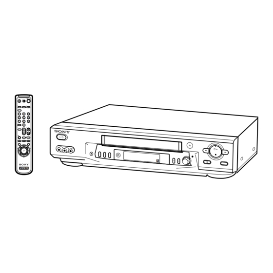
- Page 1 SLV-ED115/ED215/ED313/ED515/ED616/ED815/ED817/ ED818/ED915/ED919/EZ111/EZ212/EZ414/ EZ715/EZ717 RMT-V309/V311/V311A/V311B/V311C/V311D/V311E SERVICE MANUAL Australian Model SLV-EZ111AZ/EZ212AZ/EZ414AZ/ EZ715AS/EZ717AS E Model SLV-ED115PS/ED215PS/ED515PS/ ED815PS//ED817PS/ED915PS Hong Kong Model SLV-ED919MI ME Model SLV-ED313ME/ED313MJ/ED313SG/ ED616ME/ED616MJ/ED616SG/ ED818ME/ED818SG New Zealand Model VIDEO SLV-EZ715NZ/EZ717NZ SLV-ED818 Thai Model SLV-ED215TH/ED815TH/ED817TH/ ED915TH S MECHANISM • Refer to the SERVICE MANUAL of VHS MECHANICAL ADJUSTMENTS VI for MECHANICAL ADJUSTMENTS.
-
Page 2: Specifications
LINE WITH MARK ! ON THE SCHEMATIC DIAGRAMS AND IN THE PARTS LIST ARE CRITICAL TO SAFE OPERATION. REPLACE THESE COMPONENTS WITH SONY PARTS WHOSE PART NUMBERS APPEAR AS SHOWN IN THIS MANUAL OR IN SUPPLEMENTS PUB- LISHED BY SONY. -
Page 3: Feature Difference
• Feature Difference SLV- ED115 ED215 ED313 ED515 ED616 ED815 ED817 ED818 ED915 ED919 FEATURE PS, TH SG, ME, MJ SG, ME, MJ SG, ME PS, TH HEAD/CH NTSC (3.58) (REC/PB) (4.43) (REC/PB) ME-SECAM (REC/PB) REC (NTSC) (SP/EP) (PAL) (SP/LP) RCA REAR LINE INPUT 2pin 2pin... -
Page 4: Table Of Contents
TABLE OF CONTENTS Section Title Page Section Title Page Feature Difference ..............3 INTERFACE, IC PIN FUNCTION DESCRIPTION SERVICE NOTE ..............5 5-1. System Control-Video Block Interface (MA-402 BOARD IC101) ..........5-1 GENERAL 5-2. System Control-Servo Peripheral Circuit Interface (MA-402 BOARD IC101) ..........5-1 Getting Started .............. -
Page 5: Service Note
SERVICE NOTE 1. DISASSEMBLY • This set can be disassembled in the order shown below. Note: Pages in indicated pages in the SERVICE MANUAL. Pages in indicated pages in the VHS MECHANICAL ADJUSTMENT MANUAL VI. Upper case (Page 2-1) Front Panel Pinch Press Ground Shaft Rear... -
Page 6: General
Using the remote commander AERIAL OUT Remote sensor You can use this remote Mains lead commander to operate this VCR and a Sony TV. Buttons AERIAL IN to mains on the remote commander marked with a dot (•) can be : Signal flow Aerial cable (supplied) used to operate your Sony TV. -
Page 7: Presetting Channels
VCR and TV using the audio/video cable (see “To a TV that has audio/video input jacks” on page 7). If the same symptom persists, consult your nearest Sony dealer. The WAIT indicator goes off when all receivable channels are preset. - Page 8 Step 5: Presetting channels (continued) Presetting channels manually PROG +/– Press PROG +/– to select the programme Selected programme PROG position position. Before you start… TUNER PRESET PROG14 • Turn on the VCR and the TV. SYSTEM • D / K B / G MENU •...
- Page 9 Step 5: Presetting channels (continued) Channel numbers in the CHANNEL SET field and the corresponding channels TV system TV system Country Country Western Western Australia Morocco Indonesia Australia Morocco Indonesia Europe Europe Zealand Zealand Channel number Channel number Corresponding channels in the CHANNEL in the CHANNEL Corresponding channels...
- Page 10 Step 5: Presetting channels (continued) TV system Country East China UK/Hong Ireland South U.S.A. Japan TV system Europe Kong Africa Country East China UK/Hong Ireland South U.S.A. Japan Channel Europe Kong Africa number in Corresponding channels Channel CHANNEL number in SET column Corresponding channels CHANNEL...
- Page 11 – – – The G-CODE system is a feature – – – – – – – – included in Sony VCRs that simplifies SELECT GUIDE CH MENU programming the VCR to make timer CONFIRM recordings. To use the G-CODE system,...
-
Page 12: Setting The Clock
Step 7: Changing/disabling programme positions (continued) Press M/m until the selected channel and SET UP CH AND G-CODE guide channel row moves to the desired Disabling unwanted PROG GUIDE PLAY – programme position. programme positions – – The selected channel and guide channel –... -
Page 13: Playing A Tape
Basic Operations Playing a tape Set the year, hour and minute in sequence, CLOCK SET using , to select the item to be set, and PLAY 2 . 1 . 2 0 0 1 TUE 5 : 3 0 M/m to select the digits. EJECT CLEAR SELECT... - Page 14 Recording TV programmes (continued) Recording TV programmes REC SPEED Press REC SPEED to select the tape speed (SP or LP for the PAL INPUT SELECT colour system, and SP or EP for the NTSC colour system). LP (Long Play) provides recording time twice as long as SP (Standard Play).
- Page 15 Recording TV programmes using the Easy Timer function (continued) Set the recording stop time in the same way as in step 2, then push EASY TIMER the EASY TIMER knob. Setting or changing the A programme number flashes. Easy Clock When “–:–...
- Page 16 Recording TV Tips programmes • To record from a source connected to the LINE-1 IN or LINE-2 IN jacks, press INPUT SELECT or PROG +/– or turn the EASY TIMER knob to display “L1” or “L2” in the display window. using the G-CODE •...
-
Page 17: Basic Operations
Setting the timer Setting the timer manually (continued) manually To record the same programme every day or the same day every week, press m while the date is flashing. For details, see “Daily/ weekly recording” below. You can preset up to eight programmes at a time. - Page 18 Searching using Searching using the Blank Search the index EASY TIMER function function knob This feature enables you to find a blank The VCR marks the tape with an index ./> section on your tape. signal at the point where each recording INDEX SEARCH begins.
-
Page 19: Additional Operations
Additional Operations Setting the Playing/searching recording at various speeds duration time ×2 After you have started recording in the H PLAY normal way, you can have the VCR stop y SLOW recording automatically after a specified m REW M FF duration. -
Page 20: Adjusting The Picture
Recording stereo and bilingual Recording stereo and bilingual programmes (continued) programmes Bilingual programme To listen to On-screen display Display window In the ZWEITON (German stereo) system Main MAIN STEREO This VCR automatically receives and records stereo and bilingual STEREO programmes based on the ZWEITON system. When a stereo or bilingual programme is received, the STEREO indicator appears in the display Main and sub MAIN/SUB... -
Page 21: Additional Information
Insert a source tape with its safety tab removed into the other Be sure to use the Sony T-25CLD, T-25CLW or E-25CLDR video head cleaning (playback) VCR. Search for the point to start playback and set it to cassette. -
Page 22: Index To Parts And Controls
Index to parts and controls Index to parts and controls (continued) Display window Refer to the pages indicated in parentheses ( ) for details. Front panel STEREO CLOCK START STOP NTSC NICAM 3 4 5 1 Timer indicator (41) 8 APC (Adaptive Picture Control) indicator (64) 2 NICAM indicator (61) 9 Tracking indicator (63) -
Page 23: Disassembly
SLV-ED115/ED215/ED313/ED515/ED616/ED815/ED817/ED818/ED915/ED919/EZ111/ EZ212/EZ414/EZ715/EZ717 SECTION 2 DISASSEMBLY NOTE: Follow the disassembly procedure in the numerical order given. 2-1. CASE, FRONT PANEL BLOCK ASSEMBLY 1 Two tapping screws 3 Upper case 4 Flat Cable FDI-002 2 Two tapping screws Hooks 5 Flat Cable FDM-010... -
Page 24: Rear Panel
2-3. REAR PANEL 2 Rear panel (Engaged by the seven hooks) Hooks Hooks Hooks Hooks 1 POWER code stopper 2-4. MA-402 BOARD 1 Six screws (Sumitite (B3) +BV) 2 MA-402 board with mechanism deck... -
Page 25: Mechanism Deck
2-5. MECHANISM DECK 4 Flat cable FMD-022/FMD-023 3 Flat Cable FAC-009 5 Harness FE-127 6 Two screws (BVTP 3 × 12) 9 Screw 2 Screw (BVTP 3 × 12) (Sumitite (B3), +BV) qs Mechanism deck 1 Flexible cable CN331 CN202 qa MA-402 board 0 MD base (R) Note: When mounting the mechanism deck,... -
Page 26: Internal Views
2-6. INTERNAL VIEWS Drum assembly (M901) (DZH-89D-R) 1-772-360-11 (ED115/ED215/ED313/EZ111/EZ212) Drum assembly (M901) (DZH-0D1A-R) 1-796-012-11 (ED815/ED817/ED818/ED915/ED919/EZ715/EZ717) Drum assembly (M901) (DZH-0D0A-R) 1-796-011-11 (ED515/ED616/EZ414) ACE head assembly A-6775-791-A FE head 1-500-471-11 Q001 Tape end sensor 8-729-043-84 Q002 Tape top sensor 8-729-043-84 D001 Tape top/end LED 8-719-048-26 Drum assembly (M901) (DZH-89D-R) 1-772-360-11 (ED115/ED215/ED313/EZ111/EZ212) -
Page 27: Circuit Boards Location
2-7. CIRCUIT BOARDS LOCATION MA-402 GK-12 (ZWEITON) VIDEO, AUDIO, (EZ715AS/EZ717AS) SERVO/SYSTEM CONTROL, NK-11 (NICAM) TUNER, POWER SUPPLY (ED915/ED919/ EZ715NZ/EZ717NZ) DM-98 (USER CONTROL) FJ-31 (LINE 2 IN) DI-81 (DIAL TIMER) 2-5E... -
Page 28: Block Diagrams
SLV-ED115/ED215/ED313/ED515/ED616/ED815/ED817/ED818/ED915/ED919/EZ111/EZ212/EZ414/EZ715/EZ717 SECTION 3 BLOCK DIAGRAMS 3-1. OVERALL BLOCK DIAGRAM (SEE PAGE 4-7,4-11, 4-15) EXCEPT ED115/ED215/ ED313/EZ111/EZ212 ED815/ED817/ED818/ ED915/ED919/EZ715/ EZ717... -
Page 29: Video Block Diagram
SLV-ED115/ED215/ED313/ED515/ED616/ED815/ED817/ED818/ED915/ED919/EZ111/EZ212/EZ414/EZ715/EZ717 3-2. VIDEO BLOCK DIAGRAM IC101ql REC/PB IC201y; REC/PB IC201tk REC/PB IC2914 PB IC291w; PB IC2914 REC IC201uk PB 320mVp-p (H) REC:512mVp-p (H) 2.1Vp-p (H) 2.2Vp-p (H) 152mVp-p (H) 2.36Vp-p (15.7KHz) PB :584mVp-p (H) 640mVp-p (H) IC201ug REC/PB IC201ul PB 496mVp-p (4.43MHz)(PAL) -
Page 30: Servo/System Control Block Diagram
SLV-ED115/ED215/ED313/ED515/ED616/ED815/ED817/ED818/ED915/ED919/EZ111/EZ212/EZ414/EZ715/EZ717 3-3. SERVO/SYSTEM CONTROL BLOCK DIAGRAM IC1013 REC/PB 5.0Vp-p (25KHz) IC1014 REC 5.0Vp-p (25KHz) IC101_ REC/PB 2.6Vp-p (31.847KHz) IC101} REC/PB IC1016 REC/PB 2.6Vp-p (31.847KHz) IC1019 REC/PB 5.0Vp-p (25KHz) 3.8Vp-p IC1016 REC/PB 4.32Vp-p (15.7KHz) IC1015 REC/PB 5.0Vp-p (25KHz) IC1013 REC 4.64Vp-p (25KHz) IC1014 REC 4.64Vp-p (25KHz) -
Page 31: Audio Block Diagram
SLV-ED115/ED215/ED313/ED515/ED616/ED815/ED817/ED818/ED915/ED919/EZ111/EZ212/EZ414/EZ715/EZ717 3-4. AUDIO BLOCK DIAGRAM... -
Page 32: Tuner Block Diagram
SLV-ED115/ED215/ED313/ED515/ED616/ED815/ED817/ED818/ED915/ED919/EZ111/EZ212/EZ414/EZ715/EZ717 3-5. TUNER BLOCK DIAGRAM 3-10... -
Page 33: Mode Control Block Diagram
SLV-ED115/ED215/ED313/ED515/ED616/ED815/ED817/ED818/ED915/ED919/EZ111/EZ212/EZ414/EZ715/EZ717 3-6. MODE CONTROL BLOCK DIAGRAM 3-11 3-12... -
Page 34: Power Block Diagram
SLV-ED115/ED215/ED313/ED515/ED616/ED815/ED817/ED818/ED915/ED919/EZ111/EZ212/EZ414/EZ715/EZ717 3-7. POWER BLOCK DIAGRAM 3-13 3-14E... -
Page 35: Printed Wiring Boards And Schematic Diagrams
SLV-ED115/ED215/ED313/ED515/ED616/ED815/ED817/ED818/ED915/ED919/EZ111/ EZ212/EZ414/EZ715/EZ717 SECTION 4 PRINTED WIRING BOARDS AND SCHEMATIC DIAGRAMS THIS NOTE IS COMMON FOR PRINTED WIRING BOARDS AND SCHEMATIC DIAGRAMS. (In addition to this, the necessary note is printed in each block.) (For printed wiring boards) • : Pattern from the side which enables seeing. -
Page 36: Frame Schematic Diagram
SLV-ED115/ED215/ED313/ED515/ED616/ED815/ED817/ED818/ED915/ED919/EZ111/EZ212/EZ414/EZ715/EZ717 4-1. FRAME SCHEMATIC DIAGRAM FRAME SCHEMATIC DIAGRAM... -
Page 37: Printed Wiring Boards And Schematic Diagrams
SLV-ED115/ED215/ED313/ED515/ED616/ED815/ED817/ED818/ED915/ED919/EZ111/EZ212/EZ414/EZ715/EZ717 4-2. PRINTED WIRING BOARDS AND SCHEMATIC DIAGRAMS MA-402 (VIDEO, AUDIO, I/O, SERVO/SYSTEM CONTROL, TUNER, MODE CONTROL, POWER SUPPLY) PRINTED WIRING BOARD — Ref. No. MA-402 Board:1,000 Series — There are few cases that the part printed on this diagram isn’t mounted in this model. - Page 38 SLV-ED115/ED215/ED313/ED515/ED616/ED815/ED817/ED818/ED915/ED919/EZ111/EZ212/EZ414/EZ715/EZ717 MA-402 BOARD CN031 IC141 CN051 IC142 I-12 CN071 IC201 C-10 CN072 IC291 CN104 I-12 IC301 A-10 CN105 I-12 IC451 CN201 B-10 IC502 CN202 B-12 IC600 CN204 B-10 IC601 CN331 IC660 CN332 D-12 IC662 C-12 CN334 J-13 IC701 H-13 CN411...
-
Page 39: Video, Audio) Schematic Diagram
SLV-ED115/ED215/ED313/ED515/ED616/ED815/ED817/ED818/ED915/ED919/EZ111/EZ212/EZ414/EZ715/EZ717 MA-402 (VIDEO, AUDIO) SCHEMATIC DIAGRAM – Ref. No: MA-402 Board; 1000 series – • See page 4-5 for printed wiring board. MA-402 BOARD(1/8) ED919/ED915/ED818/ED817/ED616/EZ717 XX MARK:NO MOUNT AV-SS IC291 NO MARK:REC/PB MODE EXCEPT ED115/ED215/ED313/ED817/ EZ414/EZ212/EZ111 R :REC MODE Q202... - Page 40 SLV-ED115/ED215/ED313/ED515/ED616/ED815/ED817/ED818/ED915/ED919/EZ111/EZ212/EZ414/EZ715/EZ717 MA-402 BOARD (1/8) (VIDEO, AUDIO BLOCK) 6 IC201 ua REC/PB 1 IC201 ia REC/PB qa IC201 wh REC/PB qh IC291 qk PB 608 mVp-p (3.58 MHz) (NTSC) 1.9 Vp-p (H) 5.3 Vp-p (H) REC: 512 mVp-p (H) PB : 584 mVp-p (H) 7 IC201 y;...
-
Page 41: System Control) Schematic Diagram
SLV-ED115/ED215/ED313/ED515/ED616/ED815/ED817/ED818/ED915/ED919/EZ111/EZ212/EZ414/EZ715/EZ717 MA-402 (SYSTEM CONTROL) SCHEMATIC DIAGRAM – Ref. No: MA-402 Board; 1000 series – • See page 4-5 for printed wiring board. MA-402 BOARD(2/8) XX MARK:NO MOUNT NO MARK:REC/PB MODE R :REC MODE P :PB MODE PLLCLK PLLDAT ENABLE SW2/MAIN/SAP... - Page 42 SLV-ED115/ED215/ED313/ED515/ED616/ED815/ED817/ED818/ED915/ED919/EZ111/EZ212/EZ414/EZ715/EZ717 MA-402 BOARD (2/8) (SYSTEM CONTROL) 1 IC101 6 REC/PB 6 IC101 3 REC/PB !¡ IC101 E REC/PB 5.0 Vp-p (25Hz) 5.0 Vp-p (25Hz) 5.0 Vp-p (25Hz) !™ IC101 _ REC/PB 2 IC101 5 REC/PB 7 IC101 9 REC/PB 5.0 Vp-p (25Hz) 3.8 Vp-p...
-
Page 43: Servo Control) Schematic Diagram
SLV-ED115/ED215/ED313/ED515/ED616/ED815/ED817/ED818/ED915/ED919/EZ111/EZ212/EZ414/EZ715/EZ717 MA-402 (SERVO CONTROL) SCHEMATIC DIAGRAM – Ref. No: MA-402 Board; 1000 series – • See page 4-5 for printed wiring board. MA-402 BOARD(3/8) IC031 LB1943N XX MARK:NO MOUNT NO MARK:REC/PB MODE IC031 R :REC MODE P :PB MODE CAM MOTOR DRIVER... -
Page 44: Hi-Fi Audio) Schematic Diagram
SLV-ED115/ED215/ED313/ED515/ED616/ED815/ED817/ED818/ED915/ED919/EZ111/EZ212/EZ414/EZ715/EZ717 MA-402 (Hi-Fi AUDIO) SCHEMATIC DIAGRAM – Ref. No: MA-402 Board; 1000 series – • See page 4-5 for printed wiring board. MA-402 BOARD(4/8) XX MARK:NO MOUNT NO MARK:REC/PB MODE R :REC MODE P :PB MODE ED815/ED817/ED818/ED915/ED919/EZ715/EZ717 C315 C313 8200p... -
Page 45: Tuner) Schematic Diagram
SLV-ED115/ED215/ED313/ED515/ED616/ED815/ED817/ED818/ED915/ED919/EZ111/EZ212/EZ414/EZ715/EZ717 MA-402 (TUNER) SCHEMATIC DIAGRAM – Ref. No: MA-402 Board; 1000 series – • See page 4-5 for printed wiring board. TU701 MA-402 BOARD(5/8) TUNER (TU BLOCK) XX MARK:NO MOUNT AERIAL NO MARK:REC/PB MODE 10 11 12 13 14 15 16... - Page 46 SLV-ED115/ED215/ED313/ED515/ED616/ED815/ED817/ED818/ED915/ED919/EZ111/EZ212/EZ414/EZ715/EZ717 MA-402 (I/O) SCHEMATIC DIAGRAM – Ref. No: MA-402 Board; 1000 series – • See page 4-5 for printed wiring board. MA-402 BOARD(6/8) DISPLAY CONTROL(FRONT BLOCK) XX MARK:NO MOUNT NO MARK:REC/PB MODE SW12V R913 MA-402 (8/8) L901 LINE OUT AUDIO...
-
Page 47: Mode Control) Schematic Diagram
SLV-ED115/ED215/ED313/ED515/ED616/ED815/ED817/ED818/ED915/ED919/EZ111/EZ212/EZ414/EZ715/EZ717 MA-402 (MODE CONTROL) SCHEMATIC DIAGRAM – Ref. No: MA-402 Board; 1000 series – • See page 4-5 for printed wiring board. MA-402 BOARD(7/8) MODE CONTROL BLOCK XX MARK:NO MOUNT NO MARK:REC/PB MODE FLUORESCENT INDICATOR TUBE ND451 FL65 FL64 SCK1... - Page 48 SLV-ED115/ED215/ED313/ED515/ED616/ED815/ED817/ED818/ED915/ED919/EZ111/EZ212/EZ414/EZ715/EZ717 MA-402 (POWER SUPPLY) SCHEMATIC DIAGRAM – Ref. No: MA-402 Board; 1000 series – • See page 4-5 for printed wiring board. MA-402 BOARD(8/8) XX MARK:NO MOUNT NO MARK:REC/PB MODE L660 68uH JL618 +30V SW5V MA-402 (5/8) (SEE PAGE 4-21)
-
Page 49: Printed Wiring Board And Schematic Diagram
SLV-ED115/ED215/ED313/ED515/ED616/ED815/ED817/ED818/ED915/ED919/EZ111/EZ212/EZ414/EZ715/EZ717 GK-12 (ZWEITON) PRINTED WIRING BOARD AND SCHEMATIC DIAGRAM – Ref. No.: GK-12 board; 2,000 series – – SLV-EZ715AS/EZ717AS – There are few cases that the part isn't mounted in this model is printed on this diagram. GK-12 GK-12 BOARD(SIDE A) - Page 50 SLV-ED115/ED215/ED313/ED515/ED616/ED815/ED817/ED818/ED915/ED919/EZ111/EZ212/EZ414/EZ715/EZ717 NK-11 (NICAM) PRINTED WIRING BOARD AND SCHEMATIC DIAGRAM – Ref. No.: NK-11 board; 3,000 series – – SLV-ED915/ED919/EZ715NZ/EZ717NZ – There are few cases that the part isn't mounted in this model is printed on this diagram. NK-11 NK-11 BOARD(SIDE A)
-
Page 51: Printed Wiring Boards And Schematic Diagrams
SLV-ED115/ED215/ED313/ED515/ED616/ED815/ED817/ED818/ED915/ED919/EZ111/EZ212/EZ414/EZ715/EZ717 FJ-31 (LINE 2 IN) AND DM-98 (FUNCTION) PRINTED WIRING BOARDS AND SCHEMATIC DIAGRAMS — Ref. No. FJ-31 Board:1,000 Series — — Ref. No. DM-98 Board:2,000 Series — There are few cases that the part printed FJ-31 (LINE 2 IN) FJ-31 BOARD on this diagram isn’t mounted in this model. -
Page 52: Servo/System Control
SLV-ED115/ED215/ED313/ED515/ED616/ED815/ED817/ED818/ED915/ED919/EZ111/ EZ212/EZ414/EZ715/EZ717 DI-81 (DIAL TIMER) PRINTED WIRING BOARD AND SCHEMATIC DIAGRAM — Ref. No. DI-81 Board:2,000 Series — There are few cases that the part printed DI-81 BOARD on this diagram isn’t mounted in this model. MA-402 GK-12 (ZWEITON) VIDEO, AUDIO,... -
Page 58: Error Codes
SLV-ED115/ED215/ED313/ED515/ED616/ED815/ED817/ED818/ED915/ED919/EZ111/ EZ212/EZ414/EZ715/EZ717 SECTION 6 ERROR CODE This set displays an error code, and a mode code in case of Table 6-2. Mode Codes in Case of Error error on the display tube, if the operation stopped by error. Code Description The following provides description concerned. -
Page 59: Adjustments
SLV-ED115/ED215/ED313/ED515/ED616/ED815/ED817/ED818/ED915/ED919/EZ111/ EZ212/EZ414/EZ715/EZ717 SECTION 7 ADJUSTMENTS 2-1-3. Set-up of Adjustment During the adjustment, see the Parts Arrangement In this adjustment, PAL or NTSC pattern generator is connected Diagram for Adjustments on Page 7-6. with LINE input signal terminal. When checking with tuner, connected AERIAL terminal. -
Page 60: Adjusting Sequence
2-1-6. Adjusting Sequence 2-3. SERVO SYSTEM ADJUSTMENT Make the electrical adjustment in the following sequence. 2-3-1. RF Switching Position Adjustment Power supply adjustment (MA-402 BOARD) Purpose: Adjust the interval between A ch and B ch of tape playback output. Improve the interchangeability with other tapes and sets. Servo system adjustment When it is out of order, the interval appears on the screen, the screen is disturbed. -
Page 61: Audio System Adjustments
2-4. AUDIO SYSTEM ADJUSTMENTS RF SWP • Adjust both Lch and Rch. [Connection] Audio Audio level meter or generator distortion meter 600 Ω 47 kΩ Attenuator AUDIO LINE IN Feed signal both AUDIO LINE OUT channelssimultaneously. Fig. 7-2-5. Fig. 7-2-4. 2. -
Page 62: Overall S/N Check
Confirmation Method: 1) Supply an audio signal of 400 Hz, –7.5 dBs simultaneously to 2. E-E Output Level Check both L and R channels of Audio Line Input. (SLV-ED115/ED215/ED313/ED515/ED616/ 2) Make recording EZ111/EZ212/EZ414) 3) Play back a recorded portion. 4) Confirm that a playback level is –7.5 ±2.0 dBs. -
Page 63: Overall S/N Check
4. Overall Level Characteristic and Distortion Factor 2-5. TUNER SYSTEM ADJUSTMENT Check Purpose: [Connection] Check the record level, play level, and distortion factor against the reference input. Audio level meter Up channel Mode REC and PB (SP mode) 47 kΩ convertor Signal 400 Hz, –7.5 dBs... -
Page 64: Parts Arrangement Diagram For Adjustments
2-6. PARTS ARRANGEMENT DIAGRAM FOR ADJUSTMENTS MA-402 BOARD (Side A) CN202 JS401 GK-12 BOARD (Side A) RV001 SEPARATION ADJ IC001 7-6E... -
Page 65: Repair Parts List
X-3951-365-1 PANEL ASSY, FRONT (ED815) 1-476-475-61 COMMANDER, STANDARD (RMT V-311E) 3-953-432-01 SPRING (GE), FL (EZ111/EZ715) 4-921-277-41 SCREW (B2.6 x 8), TAPPING, BIND 3-943-995-01 EMBLEM (NO.5), SONY A-6713-876-A DM-098 COMPLETE PWB (ED115/ED313/EZ111/EZ212/EZ414) 3-943-995-31 EMBLEM (NO.5), SONY 1-757-552-12 FLAT CABLE FDM-010 (ED215/ED515/ED616/ED815/ED817/ED818/... -
Page 66: Chassis Section
SLV-ED115/ED215/ED313/ED515/ED616/ED815/ED817/ED818/ED915/ED919/EZ111/EZ212/EZ414/EZ715/EZ717 8-1-2. CHASSIS SECTION Ref. No. Part No. Description Remarks 3-959-383-01 BASE (R), MD * 52 A-6713-865-A MA-402 COMPLETE PWB (ED818) * 52 A-6713-866-A MA-402 COMPLETE PWB (ED919) * 52 A-6713-868-A MA-402 COMPLETE PWB (EZ715AS) * 52 A-6713-869-A MA-402 COMPLETE PWB (ED815) -
Page 67: Mechanism Deck Section-1
SLV-ED115/ED215/ED313/ED515/ED616/ED815/ED817/ED818/ED915/ED919/EZ111/ EZ212/EZ414/EZ715/EZ717 8-1-3. MECHANISM DECK SECTION-1 Ref. No. Part No. Description Remarks Ref. No. Part No. Description Remarks 3-977-509-01 WASHER, THRUST 3-063-773-02 OPENER, LID (SL) 3-977-507-01 TABLE, REEL (S) 3-977-441-03 GEAR, PINCH PRESSING 3-977-508-01 TABLE, REEL (T) 3-977-445-02 GEAR, TG8 ARM DRIVING... -
Page 68: Mechanism Deck Section-2
SLV-ED115/ED215/ED313/ED515/ED616/ED815/ED817/ED818/ED915/ED919/EZ111/ EZ212/EZ414/EZ715/EZ717 8-1-4. MECHANISM DECK SECTION-2 Ref. No. Part No. Description Remarks Ref. No. Part No. Description Remarks X-3949-363-1 BRAKE ASSY, MAIN (T) 3-977-501-01 PLATE, LUMINOUS 3-053-882-01 SPRING, TENS (MAIN BRAKE) A-6746-074-G ROLLER BLOCK ASSY, HC X-3947-573-1 ARM ASSY, PENDULUM... -
Page 69: Mechanism Deck Section-3
SLV-ED115/ED215/ED313/ED515/ED616/ED815/ED817/ED818/ED915/ED919/EZ111/ EZ212/EZ414/EZ715/EZ717 8-1-5. MECHANISM DECK SECTION-3 M902 M903 supplied Ref. No. Part No. Description Remarks Ref. No. Part No. Description Remarks 3-977-437-01 RETAINER, CAM MOTOR 3-063-768-01 SLIDER (SL) X-3949-364-1 ASSY, REEL DIRECT SELECT (B) 3-063-757-01 GEAR, LOADING (T) H/R 3-977-443-01 WASHER, STOPPER... -
Page 70: Electrical Parts List
SLV-LX80S DI-81 DM-98 FJ-31 Ref. No. Part No. Description Remarks Ref. No. Part No. Description Remarks 8-2. ELECTRICAL PARTS LIST NOTE: • Due to standardization, replacements in the • RESISTORS When indicating parts by reference number, parts list may be different from the parts All resistors are in ohms. - Page 71 SLV-LX80S FJ-31 GK-12 MA-402 Ref. No. Part No. Description Remarks Ref. No. Part No. Description Remarks <RESISTOR> R007 1-216-045-00 METAL CHIP 1/10W R008 1-216-041-00 METAL CHIP 1/10W R533 1-216-021-00 RES-CHIP 1/10W R009 1-216-041-00 METAL CHIP 1/10W (ED515/ED616/ED818/ R010 1-208-803-11 METAL CHIP 7.5K 0.5% 1/10W...
- Page 72 SLV-LX80S MA-402 Ref. No. Part No. Description Remarks Ref. No. Part No. Description Remarks C016 1-163-233-11 CERAMIC CHIP 18PF 5.00% 50V C172 1-163-245-11 CERAMIC CHIP 56PF 5.00% 50V C017 1-110-501-11 CERAMIC CHIP 0.33uF 10.00% 16V C191 1-163-137-00 CERAMIC CHIP 680PF 5.00% 50V C018 1-163-989-11 CERAMIC CHIP...
- Page 73 SLV-LX80S MA-402 Ref. No. Part No. Description Remarks Ref. No. Part No. Description Remarks C232 1-163-237-11 CERAMIC CHIP 27PF 5.00% 50V C307 1-124-589-11 ELECT 47uF 20.00% 16V (ED515/ED815/EZ414/EZ715) C308 1-126-964-11 ELECT 10uF 20.00% 50V C232 1-163-231-11 CERAMIC CHIP 15PF 5.00% 50V (ED616/ED817/ED818/ED915/ED919/EZ717) C309 1-163-020-00 CERAMIC CHIP...
- Page 74 SLV-LX80S MA-402 Ref. No. Part No. Description Remarks Ref. No. Part No. Description Remarks C453 1-126-157-11 ELECT 10uF 20.00% 16V C731 1-163-009-11 CERAMIC CHIP 0.001uF 10.00% 50V C454 1-163-038-00 CERAMIC CHIP 0.1uF (ED919/EZ715/EZ717) C455 1-124-584-00 ELECT 100uF 20.00% 10V C901 1-126-160-11 ELECT 20.00% 50V C456...
- Page 75 SLV-LX80S MA-402 Ref. No. Part No. Description Remarks Ref. No. Part No. Description Remarks D609 8-719-083-43 DIODE 31DQ06-FA7 JR004 1-216-295-00 SHORT D611 8-719-313-17 DIODE AU02A-V0 JR005 1-216-295-00 SHORT D612 8-719-313-17 DIODE AU02A-V0 D613 8-719-043-76 DIODE AK04V0 JR006 1-216-295-00 SHORT D614 8-719-160-64 DIODE RD16F-T8B1 JR007 1-216-295-00 SHORT...
- Page 76 SLV-LX80S MA-402 Ref. No. Part No. Description Remarks Ref. No. Part No. Description Remarks JR115 1-216-296-00 SHORT <COIL> JR116 1-216-296-00 SHORT JR117 1-216-296-00 SHORT L006 1-412-945-11 INDUCTOR 3.3uH JR118 1-216-296-00 SHORT L071 1-414-185-51 INDUCTOR 22uH JR119 1-216-296-00 SHORT (ED313/EZ111/EZ212) L072 1-414-179-51 INDUCTOR 2.2uH JR120...
- Page 77 SLV-LX80S MA-402 Ref. No. Part No. Description Remarks Ref. No. Part No. Description Remarks <TRANSISTOR> R035 1-216-689-11 RES-CHIP 1/10W R051 1-249-425-11 CARBON 4.7K 1/4W Q001 8-729-043-84 TRANSISTOR PT380F3 Q002 8-729-043-84 TRANSISTOR PT380F3 R052 1-216-065-00 RES-CHIP 4.7K 1/10W Q003 8-729-281-53 TRANSISTOR 2SC1815GR-TPE2 R053 1-247-843-11 CARBON 3.3K...
- Page 78 SLV-LX80S MA-402 Ref. No. Part No. Description Remarks Ref. No. Part No. Description Remarks R158 1-216-073-00 RES-CHIP 1/10W R227 1-216-049-00 RES-CHIP 1/10W R159 1-216-049-00 RES-CHIP 1/10W R228 1-216-049-00 RES-CHIP 1/10W R160 1-216-041-00 RES-CHIP 1/10W R289 1-216-049-00 RES-CHIP 1/10W R161 1-216-065-00 RES-CHIP 4.7K 1/10W (ED616/ED817/ED818/ED915/ED919)
- Page 79 SLV-LX80S MA-402 Ref. No. Part No. Description Remarks Ref. No. Part No. Description Remarks R379 1-249-433-11 CARBON 1/4W ! R640 1-219-153-11 FUSIBLE 1/4W R380 1-216-308-00 RES-CHIP 1/10W ! R641 1-219-153-11 FUSIBLE 1/4W (EXCEPT ED616/ED818/ED915) R643 1-216-353-00 METAL OXIDE R380 1-216-005-00 RES-CHIP 1/10W (ED616/ED818/ED915) R647...
- Page 80 SLV-LX80S MA-402 NK-11 Ref. No. Part No. Description Remarks Ref. No. Part No. Description Remarks <TRANSFORMER> < CONNECTOR > T371 1-423-414-11 TRANSFORMER, BIAS OSCILLATION * CN001 1-691-183-11 CONNECTOR (BOARD TO BOARD) 13P T372 1-423-415-11 TRANSFORMER, BIAS OSCILLATION (ED616/ED818/ED915) < DIODE > ! T600 1-435-790-11 TRANSFORMER, CONVERTER D001...
- Page 81 SLV-LX80S Ref. No. Part No. Description Remarks Ref. No. Part No. Description Remarks 1-757-552-12 FLAT CABLE FDM-010 1-476-475-21 COMMANDER, STANDARD (RMT-V311E) 1-757-553-11 FLAT CABLE FDI-002 (EZ111) 1-500-471-11 FE HEAD 1-476-475-41 COMMANDER, STANDARD (RMT-V311C) A-6759-620-A HEAD BLOCK ASSY, ACE (ED919) 1-763-572-11 MOTOR, DC 1-476-475-31 COMMANDER, STANDARD (RMT-V311B) X-3950-970-1 MOTOR ASSY, CAM (SL) (ED616/ED818)
- Page 82 SLV-ED115/ED215/ED313/ED515/ED616/ED815/ED817/ED818/ED915/ED919/EZ111/ SLV-LX80S EZ212/EZ414/EZ715/EZ717 Ref. No. Part No. Description Remarks Ref. No. Part No. Description Remarks 2001A0800-1 Sony Corporation 2001. 1 NETWORK ENTERTAINMENT GROUP 9-921-787-11 Published by Quality Assurance Dept. 8-20 – 107 –...