Table of Contents
Advertisement
SLV-ED15/ED25/ED33/ED39/ED55/ED66/ED85/ED88/ED89/
SERVICE MANUAL
S MECHANISM
• Refer to the SERVICE MANUAL of VHS MECHANICAL
ADJUSTMENTS VI for MECHANICAL ADJUSTMENTS.
(9-921-647-11)
* The abbreviations of ED15/ED25/ED33/ED39/ED55/ED66/ED85/
ED88/ED89/ED95/EZ11/EZ22/EZ44/EZ66 and EZ77 contained in this
service manual are indicated when these models are common to all
their corresponding models as given below.
Abbreviated
ED15
ED25
ED33
model name
All model
ED25PS
ED33ME
ED15PS
names
ED25TH
ED33MJ
SLV-
ED33SG
ED95/EZ11/EZ22/EZ44/EZ66/EZ77
RMT-V296/V296A/V296B/V298/V298A/V298B/V298C/V298D
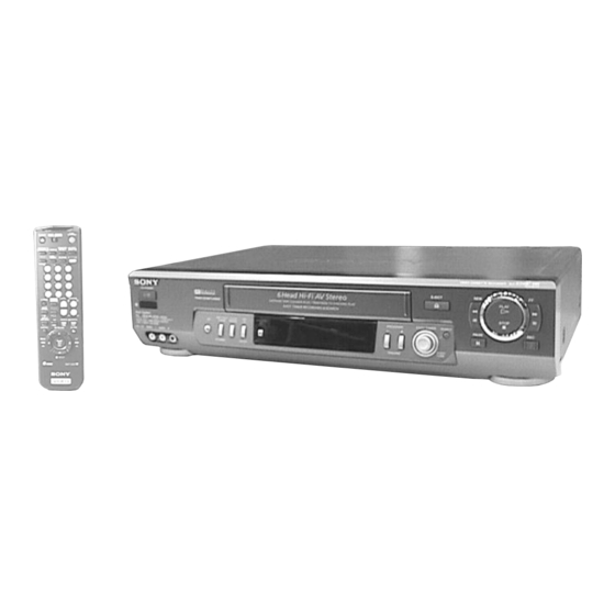
Photo: SLV-ED89AF
ED39
ED55
ED66
ED85
ED66ME
ED85PS
ED39AF
ED55PS
ED66MJ
ED85TH
ED66SG
ED95
ED88
ED89
EZ11
ED88ME
ED89AF ED95MI
EZ11AZ
EZ22AZ
ED88MJ
ED95MN
ED88SG
ED95TH
VIDEO CASSETTE RECORDER
African Model
SLV-ED39AF/ED89AF
Australian Model
SLV-EZ11AZ/EZ22AZ/EZ44AZ/
EZ66AZ/EZ77AS
E Model
SLV-ED15PS/ED25PS/ED55PS/
ED85PS/ED95M1/ED95MN
ME Model
SLV-ED33ME/ED33SG/ED66ME/
ED66SG/ED88ME/ED88SG
Middle East Model
SLV-ED33MJ/ED66MJ/ED88MJ
New Zealand Model
SLV-EZ77NZ
Thai Model
SLV-ED25TH/ED85TH/ED95TH
EZ22
EZ44
EZ66
EZ77
EZ44AZ
EZ66AZ
EZ77AS
EZ77NZ
Advertisement
Table of Contents

Related Manuals for Sony SLV-ED15


Summary of Contents for Sony SLV-ED15
- Page 1 SLV-ED15/ED25/ED33/ED39/ED55/ED66/ED85/ED88/ED89/ ED95/EZ11/EZ22/EZ44/EZ66/EZ77 RMT-V296/V296A/V296B/V298/V298A/V298B/V298C/V298D SERVICE MANUAL African Model SLV-ED39AF/ED89AF Australian Model SLV-EZ11AZ/EZ22AZ/EZ44AZ/ EZ66AZ/EZ77AS E Model SLV-ED15PS/ED25PS/ED55PS/ ED85PS/ED95M1/ED95MN ME Model SLV-ED33ME/ED33SG/ED66ME/ ED66SG/ED88ME/ED88SG Middle East Model SLV-ED33MJ/ED66MJ/ED88MJ New Zealand Model Photo: SLV-ED89AF SLV-EZ77NZ Thai Model SLV-ED25TH/ED85TH/ED95TH S MECHANISM • Refer to the SERVICE MANUAL of VHS MECHANICAL ADJUSTMENTS VI for MECHANICAL ADJUSTMENTS.
- Page 2 LINE WITH MARK 0 ON THE SCHEMATIC DIAGRAMS AND IN THE PARTS LIST ARE CRITICAL TO SAFE OPERATION. REPLACE THESE COMPONENTS WITH SONY PARTS WHOSE PART NUMBERS APPEAR AS SHOWN IN THIS MANUAL OR IN SUPPLEMENTS PUB- LISHED BY SONY.
-
Page 3: Feature Difference
• Feature Difference SLV- ED15 ED25 ED33 ED39 ED55 ED66 ED85 ED88 ED89 ED95 ED95 FEATURE MN, TH HEAD/CH NTSC (3.58) (REC/PB) (4.43) (REC/PB) × × × × × × × × × × × × × × × × ×... -
Page 4: Table Of Contents
TABLE OF CONTENTS Section Title Page Section Title Page Feature Difference ..............3 INTERFACE, IC PIN FUNCTION DESCRIPTION SERVICE NOTE ..............5 5-1. System Control-Video Block Interface (MA-377 BOARD IC101) ..........5-1 GENERAL 5-2. System Control-Servo Peripheral Circuit Interface (MA-377 BOARD IC101) ..........5-1 Getting Started .............. -
Page 5: Service Note
SERVICE NOTE 1. DISASSEMBLY • This set can be disassembled in the order shown below. Note: Pages in indicated pages in the SERVICE MANUAL. Pages in indicated pages in the VHS MECHANICAL ADJUSTMENT MANUAL VI. Upper case (Page 2-1) Front Panel Pinch Press Ground Shaft Rear... -
Page 6: General
SLV-ED15/ED25/ED33/ED39/ED55/ED66/ED85/ED88/ED89/ED95/EZ11/EZ22/EZ44/ EZ66/EZ77 SECTION 1 GENERAL This section is extracted from SLV-ED95MN/ ED95TH instruction manual. (3-058-425-12) - Page 15 1-10...
- Page 16 1-11...
- Page 17 1-12...
- Page 18 1-13 E 1-13...
-
Page 19: Disassembly
SLV-ED15/ED25/ED33/ED39/ED55/ED66/ED85/ED88/ED89/ED95/EZ11/EZ22/EZ44/ EZ66/EZ77 SECTION 2 DISASSEMBLY Note: Follow the disassembly procedure in the numerical order given. 2-1. UPPER CASE REMOVAL 2-3. PSM17-501 BOARD REMOVAL 4 PSM17-501 board 2 Three screws 1 Two tapping screws (B3) 1 Connector (CN600) 3 Upper case... -
Page 20: Mechanism Deck Removal
2-5. MECHANISM DECK REMOVAL 3 Flat cable (FMD-15/16) 2 Flexible board 4 Flat cable (FAC-7) (ACE head ) 1 Connector 0 Screw (FE head ) 9 Screw (BVTP3 × 12) (BVTP3 × 12) 5 Screw (B3) 6 Earth lug 8 Claw qs Mechanism deck qa Screw... -
Page 21: Internal Views
2-7. INTERNAL VIEWS Drum assembly (M901) (DZH-89D-R) 1-772-360-11 (ED15/ED25/ED33/ED39/EZ11/EZ22) Drum assembly (M901) (DZH-0A1A/Z-RP) 8-848-048-51 (ED85/ED88/ED89/ED95/EZ66/EZ77) Drum assembly (M901) (DZH-0A3A/Z-RP) ACE head assembly 8-839-050-51 (ED55/ED66/EZ44) A-6775-791-A FE head 1-500-144-11 Q001 Tape end sensor 8-729-043-84 Q002 Tape top sensor 8-729-043-84 D001 Tape top/end LED 8-719-048-26 Drum assembly (M901) (DZH-89D-R) 1-772-360-11 (ED15/ED25/ED33/ED39/EZ11/EZ22) -
Page 22: Circuit Boards Location
2-8. CIRCUIT BOARDS LOCATION NK-11 (ED95/EZ77NZ) SE-103 (NICAM) (ED39/ED89) MA-377 GK-12 (EZ77AS) (SECAM) VIDEO, AUDIO, I/O, (ZWEITON) SERVO/SYSTEM CONTROL, MF-321 TUNER, MODE CONTROL (POWER SWITCH) POWER BLOCK (PSM17-501) (POWER SUPPLY) FJ-26 (ED55/ED66/ED88/ ED89/ED95/EZ66/EZ77) (FRONT IN) DS-92 (MODE CONTROL) KK-24 (EASY TIMER, SEARCH) 2-4 E... -
Page 23: Block Diagrams
SLV-ED15/ED25/ED33/ED39/ED55/ED66/ED85/ED88/ED89/ED95/EZ11/EZ22/EZ44/EZ66/EZ77 SECTION 3 BLOCK DIAGRAMS 3-1. OVERALL BLOCK DIAGRAM EZ77AS ED95/EZ77NZ MA-377 BOARD GK-12 (SEE PAGE 4-9 to 4-26) NK-11 BOARD BOARD IC201 (SEE PAGE 4-29) (SEE PAGE 4-32) (1/2) IC001 VIDEO HEAD ED39/ED89 NICAM PROCESS ZWEITON SP CH1 PROCESS... -
Page 24: Video Block Diagram
SLV-ED15/ED25/ED33/ED39/ED55/ED66/ED85/ED88/ED89/ED95/EZ11/EZ22/EZ44/EZ66/EZ77 3-2. VIDEO BLOCK DIAGRAM ED39/ED89 SE-103 BOARD Q954 (SEE PAGE 4-28) BUFFER IC951 SECAM PROCESSOR SECAM to MUTE 4.43MHz SYNC GATE GEN to SYNC GATE /V-SEP MUTE SYNC 4.43MHz GATE BPF-A to PB/AGC to REC KILLER MODE to MUTE 2.2MHz... -
Page 25: Servo/System Control Block Diagram
SLV-ED15/ED25/ED33/ED39/ED55/ED66/ED85/ED88/ED89/ED95/EZ11/EZ22/EZ44/EZ66/EZ77 3-3. SERVO/SYSTEM CONTROL BLOCK DIAGRAM MA-377 BOARD (2/5) IC101elREC/PB M901 IC101 (SEE PAGE 4-13,17) (2/2) DRUM MOTOR EXCEPT SERVO/SYSTEM CONTROL ED15/ED25/ED33/ ED39/EZ11/EZ22 4.8Vp-p (25Hz) CN072 D VS DRUM MOTOR PLL CLK PLL CLOCK DRUM VS DRIVER PLL DATA PLL DATA... -
Page 26: Audio Block Diagram
SLV-ED15/ED25/ED33/ED39/ED55/ED66/ED85/ED88/ED89/ED95/EZ11/EZ22/EZ44/EZ66/EZ77 3-4. AUDIO BLOCK DIAGRAM MA-377 BOARD (3/5) (SEE PAGE 4-9,19,23) IC201 (2/2) NORMAL CN331 AUDIO PROCESS AUDIO REC/PB ED85/ED88/ED89/ED95/EZ66/EZ77 HEAD CLOCK SW5V Q372,Q373 (IIC) HEAD CONTROL SERVO/SYSTEM HEAD SWITCH SWITCH DATA CONTROL (IIC) SEE PAGE Q374 A MUTE Q376... -
Page 27: Tuner Block Diagram
SLV-ED15/ED25/ED33/ED39/ED55/ED66/ED85/ED88/ED89/ED95/EZ11/EZ22/EZ44/EZ66/EZ77 3-5. TUNER BLOCK DIAGRAM ED95MI EXCEPT ED95MI MA-377 BOARD (4/5) (SEE PAGE 4-21) TU702 TU701 AERIAL AERIAL 14 15 16 ED95/EZ77NZ ED95:MN,TH/ Q703 PLL CLK SERVO/SYSTEM EZ77 NK-11 BOARD CONTROL PLL DATA (SEE PAGE 4-32) BUFFER SEE PAGE ENABLE... -
Page 28: Mode Control Block Diagram
SLV-ED15/ED25/ED33/ED39/ED55/ED66/ED85/ED88/ED89/ED95/EZ11/EZ22/EZ44/EZ66/EZ77 3-6. MODE CONTROL BLOCK DIAGRAM KK-24 BOARD MA-377 BOARD (5/5) (SEE PAGE 4-36) (SEE PAGE 4-17,25) S511 CN511 CN411 ETR SW EASY TIMER PUSH/TURN ETR1 ETR1 ETR2 ETR2 AN6V SEARCH LED SEARCH D511 S512 SEARCH SEARCH SERVO/SYSTEM DS-92 BOARD... -
Page 29: Power Block Diagram
SLV-ED15/ED25/ED33/ED39/ED55/ED66/ED85/ED88/ED89/ED95/EZ11/EZ22/EZ44/EZ66/EZ77 3-7. POWER BLOCK DIAGRAM GK-12 BOARD MA-377 BOARD (SEE PAGE 4-29) (SEE PAGE 4-9 to 4-26) EXCEPT ED95MI ED95MI IC001 TU702 TU701 CN001 ZWEITON PROCESSOR EZ77AS PSM17-501 BOARD (SEE PAGE 4-39) NK-11 BOARD CN600 CN102 IC652 (SEE PAGE 4-32) -
Page 30: Printed Wiring Boards And Schematic Diagrams
SLV-ED15/ED25/ED33/ED39/ED55/ED66/ED85/ED88/ED89/ED95/EZ11/EZ22/EZ44/ EZ66/EZ77 SECTION 4 PRINTED WIRING BOARDS AND SCHEMATIC DIAGRAMS THIS NOTE IS COMMON FOR PRINTED WIRING For schematic Diagram: • Caution when replacing chip parts. BOARDS AND SCHEMATIC DIAGRAMS. New parts must be attached after removal of chip. (In addition to this, the necessary note is printed Be careful not to heat the minus side of tantalum capacitor, in each block.) -
Page 31: Frame Schematic Diagram
SLV-ED15/ED25/ED33/ED39/ED55/ED66/ED85/ED88/ED89/ED95/EZ11/EZ22/EZ44/EZ66/EZ77 4-1. FRAME SCHEMATIC DIAGRAM FE-128 FFJ-3 CN332 CN901 FULL CN531 FULL ERASE(X) FE_HEAD L2 AU R LINE 2 AUDIO R ERASE FULL ERASE(Y) AU GND AU GND HEAD FJ-26 AU GND AU GND L2 AU L LINE 2 AUDIO L... -
Page 32: Printed Wiring Boards And Schematic Diagrams
SLV-ED15/ED25/ED33/ED39/ED55/ED66/ED85/ED88/ED89/ED95/EZ11/EZ22/EZ44/EZ66/EZ77 There are few cases that the part isn't mounted in this model is printed on this diagram. 4-2. PRINTED WIRING BOARDS AND SCHEMATIC DIAGRAMS MA-377 (VIDEO, AUDIO, I/O, SERVO/SYSTEM CONTROL, TUNER, MODE CONTROL) PRINTED WIRING BOARD – Ref. No.: MA-377 board; 1,000 series –... - Page 33 MA-377 BOARD CN031 CN051 CN071 CN072 CN104 J-12 CN201 CN202 C-10 CN203 F-12 CN204 CN331 CN332 CN401 J-13 CN411 CN600 CN701 H-13 CN901 C-11 D001 D071 D101 D102 D151 D401 D403 J-11 D651 D701 D-12 D901 A-12 IC031 IC101 IC141 IC142 IC201 IC202...
-
Page 34: Ma-377 (Video, Audio) Schematic Diagram
SLV-ED15/ED25/ED33/ED39/ED55/ED66/ED85/ED88/ED89/ED95/EZ11/EZ22/EZ44/EZ66/EZ77 MA-377 (VIDEO, AUDIO) SCHEMATIC DIAGRAM • See page 4-5 for printed wiring board. – Ref. No.: MA-377 board; 1,000 series – MA-377 BOARD (1/7) *R202 *C214 :EXCEPT ED15/ED25/ED33/ED39/EZ11/EZ22 :ED15/ED25/ED33/ED39/EZ11/EZ22 :ED15/ED25/ED33/ED39/EZ11/EZ22 :EXCEPT ED15/ED25/ED33/ED39/EZ11/EZ22 ED66/ED88/ED89/ED95/EZ77 L206 100uH EZ11/EZ22/EZ44/ R296 EZ66/EZ77 R217... - Page 35 • Waveforms qh IC291 qk PB 1 IC201 ia REC/PB 6 IC201 ua REC/PB qa IC201 wh REC/PB 608 mVp-p (3.58 MHz) (NTSC) REC: 512 mVp-p (H) 1.9 Vp-p (H) 5.3 Vp-p (H) PB : 584 mVp-p (H) 2 IC201 ih, il REC 7 IC201 y;...
-
Page 36: System Control) Schematic Diagram
SLV-ED15/ED25/ED33/ED39/ED55/ED66/ED85/ED88/ED89/ED95/EZ11/EZ22/EZ44/EZ66/EZ77 MA-377 (SYSTEM CONTROL) SCHEMATIC DIAGRAM • See page 4-5 for printed wiring board. – Ref. No.: MA-377 board; 1,000 series – MA-377 BOARD (2/7) FL96 D_OUT FL97 D_IN FL95 MA-377 BOARD(7/7) FL90 (SEE PAGE 4-26) R121 FUNC_KEY2 DRUM_VS DRUM_FG... - Page 37 • Waveforms 1 IC101 wd REC/PB 6 IC101 el REC/PB qa IC101 yh REC/PB 4.8 Vp-p (25 Hz) 5.1 Vp-p (H) 5.2 Vp-p (25 Hz) 2 IC101 wf REC/PB 7 IC101 r; REC/PB qs IC101 yl REC/PB 4.7 Vp-p (757.6 Hz) 5.2 Vp-p (25 Hz) 2.6Vp-p (32.768 kHz) 3 IC101 ea REC/PB...
-
Page 38: Ma-377 (Servo Control) Schematic Diagram
SLV-ED15/ED25/ED33/ED39/ED55/ED66/ED85/ED88/ED89/ED95/EZ11/EZ22/EZ44/EZ66/EZ77 MA-377 (SERVO CONTROL) SCHEMATIC DIAGRAM • See page 4-5 for printed wiring board. – Ref. No.: MA-377 board; 1,000 series – MA-377 BOARD (3/7) DRUM_VS S102 (CAM ENCODER) DRUM_FG JL015 DRUM_PG JL001 CAP_RVS JL002 CAP_FG JL003 CAP_QR MA-377 BOARD(2/7) -
Page 39: Ma-377 (Hi-Fi Audio) Schematic Diagram
SLV-ED15/ED25/ED33/ED39/ED55/ED66/ED85/ED88/ED89/ED95/EZ11/EZ22/EZ44/EZ66/EZ77 MA-377 (Hi-Fi AUDIO) SCHEMATIC DIAGRAM • See page 4-5 for printed wiring board. – Ref. No.: MA-377 board; 1,000 series – MA-377 BOARD (4/7) TUNER_M TUNER_L MA-377 BOARD(5/7) TUNER_R HT13 (SEE PAGE 4-21) MOD_AUDIO HA21 HT42 NA_HF_OUT HA22 HT43... -
Page 40: Ma-377 (Tuner) Schematic Diagram
SLV-ED15/ED25/ED33/ED39/ED55/ED66/ED85/ED88/ED89/ED95/EZ11/EZ22/EZ44/EZ66/EZ77 MA-377 (TUNER) SCHEMATIC DIAGRAM • See page 4-5 for printed wiring board. – Ref. No.: MA-377 board; 1,000 series – MA-377 BOARD (5/7) EXCEPT ED95MI ED95MI TU702 TU701 AERIAL AERIAL 12 13 14 15 16 17 18 19 20 21 22 23 24... -
Page 41: Ma-377 (I/O) Schematic Diagram
SLV-ED15/ED25/ED33/ED39/ED55/ED66/ED85/ED88/ED89/ED95/EZ11/EZ22/EZ44/EZ66/EZ77 MA-377 (I/O) SCHEMATIC DIAGRAM • See page 4-5 for printed wiring board. – Ref. No.: MA-377 board; 1,000 series – MA-377 BOARD (6/7) SW5V SW12V MOD_VIDEO MA-377 BOARD(5/7) (SEE PAGE 4-22) AN6V MA-377 BOARD(2/7) (SEE PAGE 4-13) ED85/ED88/ED89/ED95/EZ66/EZ77 L900... -
Page 42: Ma-377 (Mode Control) Schematic Diagram
SLV-ED15/ED25/ED33/ED39/ED55/ED66/ED85/ED88/ED89/ED95/EZ11/EZ22/EZ44/EZ66/EZ77 MA-377 (MODE CONTROL) SCHEMATIC DIAGRAM • See page 4-5 for printed wiring board. – Ref. No.: MA-377 board; 1,000 series – MA-377 BOARD (7/7) ND451 FLUORESCENT INDICATOR TUBE FL96 D_OUT FL97 D_IN 10 11 12 13 14 15 16 17 18 19 20 21 22 23 24 25 26 27... -
Page 43: Printed Wiring Board And Schematic Diagram
SLV-ED15/ED25/ED33/ED39/ED55/ED66/ED85/ED88/ED89/ED95/EZ11/EZ22/EZ44/EZ66/EZ77 SE-103 (SECAM) PRINTED WIRING BOARD AND SCHEMATIC DIAGRAM – Ref. No.: SE-103 board; 2,000 series – – SLV-ED39/ED89 – There are few cases that the part isn't mounted in this model is printed on this diagram. SE-103 BOARD C958 0.01u... -
Page 44: Printed Wiring Board And Schematic Diagram
SLV-ED15/ED25/ED33/ED39/ED55/ED66/ED85/ED88/ED89/ED95/EZ11/EZ22/EZ44/EZ66/EZ77 GK-12 (ZWEITON) PRINTED WIRING BOARD AND SCHEMATIC DIAGRAM – Ref. No.: GK-12 board; 2,000 series – There are few cases that the part isn't mounted in this model is printed on this diagram. – SLV-EZ77AS – GK-12 GK-12 BOARD(SIDE A) -
Page 45: Printed Wiring Board And Schematic Diagram
SLV-ED15/ED25/ED33/ED39/ED55/ED66/ED85/ED88/ED89/ED95/EZ11/EZ22/EZ44/EZ66/EZ77 NK-11 (NICAM) PRINTED WIRING BOARD AND SCHEMATIC DIAGRAM – Ref. No.: NK-11 board; 3,000 series – – SLV-ED95/EZ77NZ – There are few cases that the part isn't mounted in this model is printed on this diagram. NK-11 NK-11 BOARD(SIDE A) -
Page 46: Printed Wiring Boards And Schematic Diagrams
SLV-ED15/ED25/ED33/ED39/ED55/ED66/ED85/ED88/ED89/ED95/EZ11/EZ22/EZ44/EZ66/EZ77 FJ-26 (FRONT IN), MF-321 (POWER SWITCH) PRINTED WIRING BOARDS AND SCHEMATIC DIAGRAMS – Ref. No.:FJ-26 board, MF-321 board; 1,000 series – There are few cases that the part isn't mounted in this model is printed on this diagram. MF-321 BOARD... - Page 47 SLV-ED15/ED25/ED33/ED39/ED55/ED66/ED85/ED88/ED89/ED95/EZ11/EZ22/EZ44/EZ66/EZ77 DS-92 (MODE CONTROL), KK-24 (EASY TIMER/SEARCH) PRINTED WIRING BOARDS AND SCHEMATIC DIAGRAMS – Ref. No.: DS-92 board, KK-24 board; 1,000 series – There are few cases that the part isn't mounted in this model is printed on this diagram.
- Page 48 SLV-ED15/ED25/ED33/ED39/ED55/ED66/ED85/ED88/ED89/ED95/EZ11/EZ22/EZ44/EZ66/EZ77 PSM17-501 (POWER SUPPLY) PRINTED WIRING BOARD – Ref. No.: PSM17-501 board; 4,000 series – There are few cases that the part isn't mounted in this model is printed on this diagram. PSM17-501 BOARD CN101 SHR1 CN102 SECONDARY PRIMARY CN103...
-
Page 49: Psm17-501 Schematic Diagram
SLV-ED15/ED25/ED33/ED39/ED55/ED66/ED85/ED88/ED89/ED95/EZ11/EZ22/EZ44/EZ66/EZ77 PSM17-501 (POWER SUPPLY) SCHEMATIC DIAGRAM – Ref. No.: PSM17-501 board; 4,000 series – PSM17-501 BOARD 47µH 1N4936 CN102 19P 100µF P6KE200A 10.8µH S3L20UF34 BYV26E 0.01µF 330µF 220µF MA-377 BOARD (3/7) 1N4744A CN600 (SEE PAGE 4-18) 10.8µH SB360 TOP225Y A/D1 IN 100µF... -
Page 50: Interface, Ic Pin Function Description
SLV-ED15/ED25/ED33/ED39/ED55/ED66/ED85/ED88/ED89/ED95/EZ11/EZ22/EZ44/ EZ66/EZ77 SECTION 5 INTERFACE, IC PIN FUNCTION DESCRIPTION... - Page 54 5-5 E...
-
Page 55: Error Codes
SLV-ED15/ED25/ED33/ED39/ED55/ED66/ED85/ED88/ED89/ED95/EZ11/EZ22/EZ44/ EZ66/EZ77 SECTION 6 ERROR CODES Table 6-2. Mode Codes in Case of Error This set displays an error code, and a mode code in case of error on the display tube, if the operation stopped by error. Code Description The following provides description concerned. -
Page 56: Adjustments
SLV-ED15/ED25/ED33/ED39/ED55/ED66/ED85/ED88/ED89/ED95/EZ11/EZ22/EZ44/ EZ66/EZ77 SECTION 7 ADJUSTMENTS 2-1-3. Set-up of Adjustment During the adjustment, see the Parts Arrangement In this adjustment, PAL or NTSC pattern generator is connected Diagram for Adjustments on Page 7-6. with LINE input signal terminal. When checking with tuner, con- nected AERIAL terminal. -
Page 57: Adjusting Sequence
2-1-6. Adjusting Sequence 2-3. SERVO SYSTEM ADJUSTMENT Make the electrical adjustment in the following sequence. 2-3-1. RF Switching Position Adjustment Power supply adjustment (MA-377 BOARD) Purpose: Adjust the interval between A ch and B ch of tape playback out- put. Servo system adjustment Improve the interchangeability with other tapes and sets. -
Page 58: Audio System Adjustments
2-4. AUDIO SYSTEM ADJUSTMENTS RF SWP • Adjust both Lch and Rch. [Connection] Audio Audio level meter or generator distortion meter 600 Ω 47 kΩ Attenuator AUDIO LINE IN Feed signal both AUDIO LINE OUT channelssimultaneously. Fig. 7-2-5. Fig. 7-2-4. 2. -
Page 59: Overall S/N Check
Refer to the SERVICE MANUAL of VHS MECHANICAL AD- JUSTMENT VI. Confirmation Method: 1) Supply an audio signal of 400 Hz, –7.5 dBs simultaneously to 2. E-E Output Level Check (SLV-ED15/ED25/ED33/ both L and R channels of Audio Line Input. ED39/ED55/ED66/ED85/ED88/ED89/EZ11/EZ22/ 2) Make recording EZ44/EZ66/EZ77) 3) Play back a recorded portion. -
Page 60: Overall S/N Check
4. Overall Level Characteristic and Distortion Factor 2-5. TUNER SYSTEM ADJUSTMENT 2-6. PARTS ARRANGEMENT DIAGRAM FOR ADJUSTMENTS Check Purpose: [Connection] MA-377 BOARD (Side A) Check the record level, play level, and distortion factor against the reference input. Audio level meter Up channel Mode REC and PB (SP mode) -
Page 61: Repair Parts List
3-057-164-11 INSULATOR (EZ77) ED55/ED66/ED88/ (ED25/ED55/ED85/ED88/ED95/EZ66/EZ77) 1-418-871-11 COMMANDER, STANDARD (RMT-V298) (EZ11) ED89/ED95/EZ66/ 1-418-871-21 COMMANDER, STANDARD (RMT-V298A) EZ77 3-943-995-01 EMBLEM (NO.5), SONY (ED15/ED33/ED39/ (ED15/ED25/ED33/ED39/ED55/ED85) 11 20 ED66/ED89/EZ11/EZ22/EZ44) 1-418-871-31 COMMANDER, STANDARD (RMT-V298B) 3-943-995-31 EMBLEM (NO.5), SONY (ED66/ED88/ED95: MN, TH) (ED25/ED55/ED85/ED88/ED95/EZ66/EZ77) 1-418-871-41 COMMANDER, STANDARD (RMT-V298C) -
Page 62: Chassis Assembly
8-1-2. CHASSIS ASSEMBLY 8-1-3. MECHANISM CHASSIS ASSEMBLY (1) ED95/EZ77 supplied ED39/ED89 supplied supplied The components identified by mark 0 or dotted line with mark 0 are critical for safety. Replace only with part number speci- supplied fied. Ref. No. Part No. Description Remark Ref. -
Page 63: Mechanism Chassis Assembly (1)
8-1-4. MECHANISM CHASSIS ASSEMBLY (2) Ref. No. Part No. Description Remark Ref. No. Part No. Description Remark X-3947-581-1 BRAKE (T) ASSY, MAIN 3-977-488-01 SPRING (POWER TENSION) 3-977-462-01 SPRING, EXTENTION. (MAIN BRAKE) A-6750-324-A SHUTTLE (S) BLOCK ASSY X-3947-573-1 ARM ASSY, PENDULUM X-3944-378-1 ROLLER ASSY, GUIDE X-3947-580-2 BRAKE (S) ASSY, MAIN 3-965-178-01 SPRING... -
Page 64: Mechanism Chassis Assembly (2)
8-1-5. MECHANISM CHASSIS ASSEMBLY (3) M902 818 803 M903 Ref. No. Part No. Description Remark Ref. No. Part No. Description Remark 3-977-437-01 RETAINER, CAM MOTOR 3-977-442-01 SLIDER X-3947-584-1 ASSY, REEL DIRECT 3-977-455-01 GEAR, LOADING (T) 3-977-443-01 WASHER, STOPPER 3-977-456-03 SPRING, TORSION (LOAD T) 3-977-438-01 WORM - WHEEL X-3947-579-1 LEVER ASSY, LOADING (T) 3-977-506-01 ARM, LIMITTER SELECTION... -
Page 65: Electrical Parts List
DS-92 FJ-26 GK-12 8-2. ELECTRICAL PARTS LIST NOTE: The components identified by • Due to standardization, replacements in the • Items marked “*” are not stocked since they mark 0 or dotted line with mark parts list may be different from the parts speci- are seldom required for routine service. - Page 66 GK-12 KK-24 MA-377 Ref. No. Part No. Description Remark Ref. No. Part No. Description Remark C012 1-107-823-11 CERAMIC CHIP 0.47uF 10.00% 16V < SWITCH > C013 1-107-823-11 CERAMIC CHIP 0.47uF 10.00% 16V C014 1-164-004-11 CERAMIC CHIP 0.1uF S511 1-418-059-22 ENCODER, ROTARY (EASY TIMER) S512 1-762-196-21 SWITCH, TACT (SEARCH) C015...
- Page 67 MA-377 Ref. No. Part No. Description Remark Ref. No. Part No. Description Remark C077 1-124-589-11 ELECT 47uF C191 1-163-133-00 CERAMIC CHIP 470PF (ED15/ED25/ED33/ED39/EZ11/EZ22) (ED66/ED88/ED95: MN, TH/EZ77) C101 1-163-038-00 CERAMIC CHIP 0.1uF C102 1-127-890-11 DOUBLE LAYER 0.47F 5.5V C192 1-163-243-11 CERAMIC CHIP 47PF 5.00% 50V (ED33/ED39/ED66/ED88/ED89)
- Page 68 MA-377 Ref. No. Part No. Description Remark Ref. No. Part No. Description Remark C228 1-163-038-00 CERAMIC CHIP 0.1uF C259 1-164-505-11 CERAMIC CHIP 2.2uF C229 1-126-163-11 ELECT 4.7uF (ED88/ED89/ED95: MN, TH/EZ77) C230 1-163-227-11 CERAMIC CHIP 10PF 0.50PF 50V C260 1-163-021-91 CERAMIC CHIP 0.01uF 10.00% 50V (ED66/ED88/ED89/ED95/EZ77)
- Page 69 MA-377 Ref. No. Part No. Description Remark Ref. No. Part No. Description Remark C320 1-126-964-11 ELECT 10uF 20.00% 50V C454 1-163-038-00 CERAMIC CHIP 0.1uF (ED85/ED88/ED89/ED95/EZ66/EZ77) C651 1-163-021-91 CERAMIC CHIP 0.01uF 10.00% 50V (ED33MJ/ED66MJ/ED88MJ) C322 1-126-964-11 ELECT 10uF 20.00% 50V C651 1-164-232-11 CERAMIC CHIP 0.01uF (ED85/ED88/ED89/ED95/EZ66/EZ77)
- Page 70 MA-377 Ref. No. Part No. Description Remark Ref. No. Part No. Description Remark C905 1-126-925-11 ELECT 470uF 20.00% 10V D403 8-719-056-06 DIODE SLR-342DCT31 (R (ED85/ED88/ED89/ED95/EZ66/EZ77) (ED66/ED88/ED89/ED95/EZ77) C906 1-104-664-11 ELECT 47uF 20.00% 25V D651 8-719-911-19 DIODE 1SS119-25TD (ED85/ED88/ED89/ED95/EZ66/EZ77) D701 8-719-119-22 DIODE RD33F-T7B1 C909 1-126-160-11 ELECT (ED88/ED89/ED95/EZ66/EZ77)
- Page 71 MA-377 Ref. No. Part No. Description Remark Ref. No. Part No. Description Remark JS718 1-216-295-00 METAL CHIP 1/10W JR021 1-216-295-00 METAL CHIP 1/10W (ED85/ED88/ED89/EZ66) JR022 1-216-295-00 METAL CHIP 1/10W JS719 1-216-295-00 METAL CHIP 1/10W JR023 1-216-295-00 METAL CHIP 1/10W (ED85/ED88/ED89/EZ66) JR024 1-216-295-00 METAL CHIP 1/10W...
- Page 72 MA-377 Ref. No. Part No. Description Remark Ref. No. Part No. Description Remark L302 1-414-857-51 INDUCTOR 100uH Q374 8-729-901-06 TRANSISTOR MUN2113T1 (ED85/ED88/ED89/ED95/EZ66/EZ77) L351 1-414-857-51 INDUCTOR 100uH Q375 8-729-012-31 TRANSISTOR 2SC4040-TL2-Q L371 1-410-120-11 INDUCTOR 1.2mH Q376 8-729-900-51 TRANSISTOR UN2115-QRS (TX) Q380 8-729-900-51 TRANSISTOR UN2115-QRS (TX) L380...
- Page 73 MA-377 Ref. No. Part No. Description Remark Ref. No. Part No. Description Remark R101 1-249-431-11 CARBON 1/4W R177 1-216-065-00 METAL CHIP 4.7K 1/10W (ED88/ED95MI) R178 1-216-033-00 METAL CHIP 1/10W R102 1-249-429-11 CARBON 1/4W (EXCEPT EZ11/EZ22/EZ44/EZ66/EZ77) R103 1-249-417-11 CARBON 1/4W R191 1-249-437-11 CARBON 1/4W R104...
- Page 74 MA-377 Ref. No. Part No. Description Remark Ref. No. Part No. Description Remark R301 1-249-429-11 CARBON 1/4W R372 1-216-037-00 METAL CHIP 1/10W (ED85/ED88/ED89/ED95/EZ66/EZ77) R375 1-216-073-00 METAL CHIP 1/10W R306 1-216-083-00 METAL CHIP 1/10W R376 1-216-073-00 METAL CHIP 1/10W (ED85/ED88/ED89/ED95/EZ66/EZ77) R307 1-216-057-00 METAL CHIP 2.2K 1/10W...
- Page 75 MA-377 MF-321 NK-11 Ref. No. Part No. Description Remark Ref. No. Part No. Description Remark R901 1-216-021-00 METAL CHIP 1/10W < TRANSFORMER > (ED85/ED88/ED89/ED95/EZ66/EZ77) R902 1-216-021-00 METAL CHIP 1/10W T371 1-423-413-11 TRANSFORMER, BIAS OSCILLATION (EXCEPT ED85/ED95MI/EZ66) (ED66/ED88/ED95: MN, TH/EZ77) R903 1-216-041-00 METAL CHIP 1/10W T371...
- Page 76 NK-11 POWER BLOCK (PSM17-501) SE-103 Ref. No. Part No. Description Remark Ref. No. Part No. Description Remark C013 1-163-243-11 CERAMIC CHIP 47PF 5.00% 50V 1-468-495-11 POWER BLOCK (PSM17-501) C014 1-164-232-11 CERAMIC CHIP 0.01uF ************************ C015 1-163-231-11 CERAMIC CHIP 15PF 5.00% 50V (Ref.
- Page 77 SE-103 Ref. No. Part No. Description Remark Ref. No. Part No. Description Remark C961 1-164-004-11 CERAMIC CHIP 0.1uF 1-792-430-11 CABLE, FLAT (FFJ-3) C963 1-163-135-00 CERAMIC CHIP 560PF (ED55/ED66/ED88/ED89/ED95/EZ66/EZ77) C964 1-163-009-11 CERAMIC CHIP 0.001uF 1-792-429-11 CABLE, FLAT (FMD-15) C965 1-164-232-11 CERAMIC CHIP 0.01uF (ED15/ED25/ED33/ED39/EZ11/EZ22) C967...
- Page 78 Ref. No. Part No. Description Remark Ref. No. Part No. Description Remark 3-058-427-11 MANUAL, INSTRUCTION (ENGLISH) (ED55/ED85) 3-058-427-21 MANUAL, INSTRUCTION (THAI) (ED85TH) 3-058-427-31 MANUAL, INSTRUCTION (RUSSIAN) (ED55/ED85PS) 3-058-428-11 MANUAL, INSTRUCTION (ENGLISH) (ED39/ED89) 3-058-428-21 MANUAL, INSTRUCTION (ARABIC) (ED39/ED89) 3-058-428-31 MANUAL, INSTRUCTION (FRENCH) (ED39/ED89) 3-058-429-11 MANUAL, INSTRUCTION (ENGLISH) (ED66/ED88)
- Page 79 SLV-ED15/ED25/ED33/ED39/ED55/ED66/ED85/ED88/ED89/ED95/EZ11/EZ22/EZ44/ EZ66/EZ77 Sony Corporation 2000B053014-1F 9-921-753-11 Home VIDEO Division Company Printed in Japan © 2000. 2 – 120 – Published by Quality Assurance Dept.