Raymarine ST60+ Owner's Handbook Manual
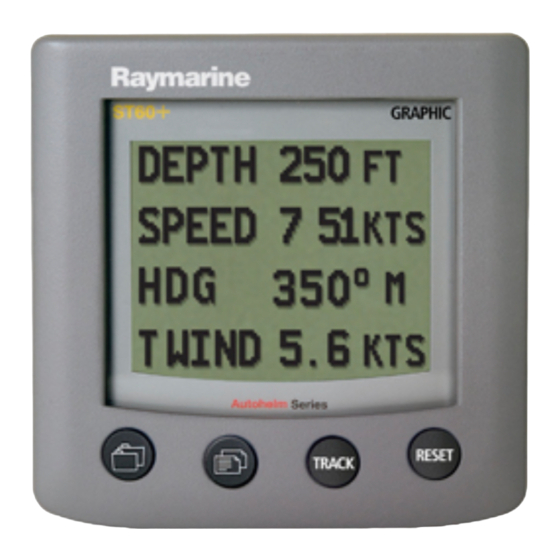
Graphic display
Hide thumbs
Also See for ST60+:
- Owner's handbook manual (62 pages) ,
- Quick start manual (2 pages) ,
- Owner's handbook manual (44 pages)

Related Manuals for Raymarine ST60+


Summary of Contents for Raymarine ST60+
- Page 1 ST60+ Graphic Display Owner’s Handbook Document reference: 81268-3 Date: August 2006...
- Page 2 Raymarine, ST60+ and SeaTalk are trademarks of Raymarine UK Limited © Handbook contents copyright Raymarine UK Limited 2006...
-
Page 3: Warning: Product Installation & Operation
Handbook information To the best of our knowledge, the information in this handbook was correct when it went to press. However, Raymarine cannot accept liability for any inaccuracies or omissions it may contain. In addition, our policy of continuous product improvement may change specifications without notice. -
Page 4: Product Disposal
The WEEE Directive requires the recycling of waste electrical and electronic equipment. Whilst the WEEE Directive does not apply to some of Raymarine's products, we support its policy and ask you to be aware of how to dispose of this product. -
Page 5: Table Of Contents
Preface Contents Preface ..........................i Important information .................... i Safety notices ....................i WARNING: Product installation & operation.......... i WARNING: Electrical safety ................i WARNING: Navigational safety ..............i EMC conformance ..................... i Handbook information ..................i Product disposal ..................... ii Contents ....................... - Page 6 ST60+ Graphic Display Owner’s Handbook 1.5 Autopilot information ..................11 1.6 Using the track button ...................11 1.7 Alarm messages .....................11 Internal alarms....................12 MOB alarm..................... 12 External alarms ....................12 Actions to take if an alarm occurs..............13 Silencing internal alarms ................ 13 Silencing external alarms ............... 13 1.8 Display settings ....................13 Illumination.....................13 Contrast ......................14...
- Page 7 Preface Auxiliary alarm option ..................26 3.3 Connecting the display ................... 27 Introduction....................27 Mandatory connections ................. 27 Optional connections ................27 Connecting to SeaTalk ..................28 Power requirements ................28 CAUTION: Protect the power supply ............28 Procedure....................29 NMEA IN and OUT connectors................
- Page 8 ST60+ Graphic Display Owner’s Handbook 4.3 Dealer calibration ...................44 Summary......................44 Procedure......................45 User calibration on/off ................45 Response settings .................. 46 Battery voltage..................46 WARNING: HIGH VOLTAGE HAZARD............46 Default reset ..................46 Self test ....................48 Leaving Dealer calibration................48 4.4 Checking operation ..................48 Basic checks....................48 NMEA checks....................48 Glossary ...........................49...
-
Page 9: Introduction
Preface Introduction Preface Thank you for purchasing a Raymarine product. We are sure your ST60+ instrument will give you many years of trouble-free operation. This handbook describes how to install and use the Raymarine ST60+ Graphic Display. This instrument provides a wide range of data, on a high quality Dot Matrix Display. -
Page 10: Remote Control
viii ST60+ Graphic Display Owner’s Handbook directly connected to a transducer but displays information provided by other equipment in the SeaTalk network. The ST60+ Graphic Display is a repeater. Remote control When connected to SeaTalk, the ST60+ Graphic Display can be controlled remotely by the SeaTalk Remote Keypad Unit. -
Page 11: Parts Supplied
Preface Parts supplied Unpack your ST60+ Graphic Display and check that the following items are present: • Item 1, ST60+ Graphic Display fitted with standard bezel for surface mounting. • Item 2, Fixing studs (2). • Item 3, Thumb nuts (2). •... - Page 12 ST60+ Graphic Display Owner’s Handbook ST60+ Graphic Display ST60 + GRAPHIC Quick Start Guide Auxiliary Alarm Option...
-
Page 13: Chapter 1: Operation
Displayed information Your ST60+ Graphic Display uses a high-quality dot-matrix screen to display a wide range of data, both from Raymarine via SeaTalk, and from other equipment via NMEA. The exact information available for display depends on what data is available and on how the display has been set up. - Page 14 AUTOPILOT ENVIRONMENT Pilot status Sea temperature Rudder angle Battery voltage Note: AUTOPILOT Time chapter available only if Date a Raymarine autopilot Sea temperature graph system is connected to SeaTalk Battery voltage graph Chapter selection and content D8269-1...
-
Page 15: Selecting Pages
Chapter 1: Operation Selecting pages Chapter selection and content To see the information you want, refer to the diagram above, to determine the location of the information you need (i.e. which chapter and page), then: 1. Press the button the necessary number of times, to select the required chapter. -
Page 16: Rolling Road
ST60+ Graphic Display Owner’s Handbook Single-element page Dual-element page Triple-element page Quad-element page Rolling road page Graph page Typical pages D6433-1 Rolling road The rolling road is a representation of your vessel’s position with respect to a waypoint, and a steer bar shows the direction you should steer to achieve the required course. -
Page 17: Chapter And
Chapter 1: Operation Timescale menu 2. Use the reset button to select the timescale value you want. 3. Hold down the reset button for 1 second, to return to the normal display, with the new timescale selected. 1.3 Chapter and page details This section lists all the available pages along with titles and salient points. -
Page 18: Speed Chapter
ST60+ Graphic Display Owner’s Handbook Speed chapter Page Remarks SPEED Boat speed, displayed in kilometers per hour ( ), miles per hour ( ), or knots ( MAX SPEED Maximum speed since power up or last reset, in kilometers per hour ( ), miles per hour ( ), or knots (... -
Page 19: Heading Chapter
Chapter 1: Operation Page Remarks TRUE WIND True wind speed, in either kilometers per hour ), meters per second (speed) M/S) , or knots ( TRUE WIND True wind angle, in degrees. (angle) GROUND Direction of wind over ground, in degrees, either (netic) or (e). -
Page 20: Navigate Chapter
ST60+ Graphic Display Owner’s Handbook Page Remarks Dual page showing course made good, in degrees, true ( ) or magnetic ( and distance made good, in either kilometers ( ), statute miles ( , or nautical miles ( To reset CMG and DMG, hold down reset for 3 seconds. Note: HEADING Heading angle in degrees, displayed against time, as a graph. -
Page 21: Environment Chapter
Chapter 1: Operation Environment chapter Page Remarks SEA TEMP °C °F. Sea temperature in either BATTERY Battery voltage. TIME & DATE Current time, as either 12- or 24-hour clock, set during User calibration (see Chapter 4, Calibration Current date, in either USA or European format, as set during User calibration Chapter 4, Calibration)). -
Page 22: Setting Up Favorite Pages
ST60+ Graphic Display Owner’s Handbook Favorite pages. You cannot include the rolling road or graphs on multi-ele- ment pages. Single-element Favorite page Typical multi-element Favorite page Can be set to show any other Each element can be set to show page, including rolling road and any available data, except rolling graphs... -
Page 23: Autopilot Information
Chapter 1: Operation 1.5 Autopilot information If a Raymarine Autopilot is connected to SeaTalk, you can use the Autopilot Chapter 4, chapter to show the current pilot status. During User calibration (see Calibration ), you can also set the ST60+ Graphic Display to show the autopilot status on pop-up pages, whenever the autopilot status changes,. -
Page 24: Internal Alarms
ST60+ Graphic Display Owner’s Handbook Internal alarms The internal alarms are as follows: Message Meaning Man Overboard alarm (see below) ANCHOR ALARM Deep or shallow anchor alarm (with current depth) SHALLOW ALARM Shallow water alarm (with current depth) DEEP ALARM Deep water alarm (with current depth) HIGH WIND ALARM... -
Page 25: Actions To Take If An Alarm Occurs
Chapter 1: Operation Actions to take if an alarm occurs If an alarm occurs, investigate the cause immediately and if possible, take appropriate action to remove the cause. If an alarm message is displayed, use this to guide your course of action. Silencing internal alarms You can silence an internal alarm by pressing any one of the ST60+ Graphic Display front panel buttons. -
Page 26: Contrast
ST60+ Graphic Display Owner’s Handbook 2. There are four preset backlighting levels. Momentarily press the button to cycle through these levels until you reach the level you want. 3. Press any other button to leave the backlighting-adjust mode. The display will time out to normal operation 5 seconds after the last button press. Note: Contrast To adjust the display contrast:... -
Page 27: Chapter 2: Maintenance & Troubleshooting
Chapter 2: Maintenance & Troubleshooting 2.1 Maintenance Servicing and safety • Raymarine equipment should be serviced only by authorised Raymarine ser- vice technicians. They will ensure that servicing procedures and replacement parts used will not affect performance. There are no user-serviceable parts in any Raymarine product. -
Page 28: Troubleshooting
ST60+ Graphic Display. If you think that data is missing, ensure that your system supports this data before assuming that a fault exists. All Raymarine products are subjected to comprehensive test and quality assurance programmes prior to packing and shipping. However, if a fault occurs, the following table may help to identify and rectify the problem. -
Page 29: Telephone Help Line
Chapter 2: Maintenance & Troubleshooting As well as providing a comprehensive Frequently Asked Questions section and servicing information, the web site gives e-mail access to the Raymarine Technical Support Department and a details of the locations of Raymarine agents, worldwide. - Page 30 ST60+ Graphic Display Owner’s Handbook...
-
Page 31: Chapter 3: Installation
Chapter 3: Installation This chapter describes how to install the ST60+ Graphic Display. For advice, or further information regarding the installation of this equipment, please contact the Raymarine Product Support Department or your own National Distributor. 3.1 Planning your installation... -
Page 32: Caution: Keep The Rear Of The Instrument Dry
• There is reasonable rear access for installation and servicing. EMC installation guidelines All Raymarine equipment and accessories are designed to the best industry standards for use in the recreational marine environment. Their design and manufacture conforms to the appropriate Electromagnetic Compatibility (EMC) standards, but correct installation is required to ensure that performance is not compromised. -
Page 33: Suppression Ferrites
Raymarine equipment. Always use the ferrites supplied by Raymarine. D3548-6 Connections to other equipment If your Raymarine equipment is to be connected to other equipment using a cable not supplied by Raymarine, a suppression ferrite MUST always be attached to the cable near the Raymarine unit. -
Page 34: Unpacking
ST60+ Graphic Display Owner’s Handbook Unpacking Preface Unpack your ST60+ equipment and check that the items described in the are present. Each ST60+ instrument is supplied with a standard bezel for surface mounting. Optional mounting kits are available for flush mounting and bracket mounting the instrument. -
Page 35: Flush Mounting
Chapter 3: Installation Surface mounting Flush mounting The Flush Mounting Kit uses a low-profile bezel to reduce the fitted profile of the instrument, to approximately 0.25 in (6 mm) above the panel fascia. Fitting the flush mount bezel In order to flush-mount your ST60+ instrument, you must first replace the standard bezel with the flush mount bezel as follows: 1. -
Page 36: Caution: Use The Correct Screws
ST60+ Graphic Display Owner’s Handbook 2. Using both thumbs, gently press an upper corner of the instrument from the bezel, then remove the bezel from the instrument. Retain the rubber keypad which is released when the bezel is removed. Fitting the flush mount bezel 3. - Page 37 Chapter 3: Installation 7. Using the four, self-tapping screws (12) provided, secure the instrument and bezel together. Fit the screws from the rear of the instrument and tighten them sufficiently to secure the instrument and bezel together. DO NOT OVER- TIGHTEN.
-
Page 38: Bracket Mounting
ST60+ Graphic Display Owner’s Handbook 4. Cut out the aperture (3) for the assembled instrument and bezel and remove the template. 5. Peel off the protective sheet from the self-adhesive gasket (4) then stick the gasket into position on the rear of the bezel. 6. -
Page 39: Connecting The Display
As it is not practical to describe connections for all possible SeaTalk configurations, the instructions given here describe the general requirement. Adapt these instructions, to suit your particular situation. A range of Raymarine SeaTalk extension cables and Raymarine 3-way SeaTalk junction boxes are available to provide maximum flexibility when installing your display. -
Page 40: Connecting To Seatalk
ST60+ Graphic Display Owner’s Handbook Connecting to SeaTalk Power requirements CAUTION: Protect the power supply Ensure that the 12 V power supply for the SeaTalk bus is protected by a 5 A fuse or circuit breaker. Systems with a large number of instruments on the SeaTalk bus may require connections to the power supply from each end of the system (‘ring-main’... -
Page 41: Procedure
Chapter 3: Installation Procedure Connect your ST60+ Graphic Display as follows: 1. Ensure that: • Power to the existing SeaTalk system is switched off. Power requirements • The conditions described under are fulfilled. 2. Plug the SeaTalk cable(s) from the rear of the display into a vacant SeaTalk connector on an adjacent instrument. -
Page 42: Caution: Connections To Other Equipment
ST60+ Graphic Display Owner’s Handbook CAUTION: Connections to other equipment If you are connecting any Raymarine product to other equip- ment, using a non-Raymarine cable, you MUST fit an appropriate suppression ferrite to the cable near to the Raymarine product. -
Page 43: Starting Procedures
Chapter 3: Installation NMEA to SeaTalk When supported NMEA data is available at the NMEA IN connector, it is decoded and displayed by the ST60+ Graphic Display. The supported NMEA input data is detailed in the following table. Data NMEA Header Bearing &... -
Page 44: Warning: Calibration Requirement
ST60+ Graphic Display Owner’s Handbook WARNING: Calibration requirement To ensure this product performs at its best on your boat, you MUST calibrate it before use, in accordance with the instructions Chapter 4, Calibration Do NOT use the product until you have successfully calibrated it. -
Page 45: Emc Conformance
Chapter 3: Installation 3. Use the button to go to the NMEA OUT on/off screen. 4. Use the track or reset button to switch the NMEA OUT function ON or OFF , as required. If you set: • NMEA ON, then the Auxiliary Alarm output is disabled and the Auxiliary Alarm Select screen (the next screen) shows ALARM DRIVE UNAVAILABLE . - Page 46 ST60+ Graphic Display Owner’s Handbook...
-
Page 47: Chapter 4: Calibration
Chapter 4: Calibration 4.1 Introduction Use this chapter to set up and check the ST60+ Graphic Display, before it is used operationally. Instructions are given to enable you to: Chapter 1, System • Define the function of the NMEA OUT connector (see Connections •... -
Page 48: Procedure
ST60+ Graphic Display Owner’s Handbook Procedure To carry out the required setup procedure: 1. Hold down the buttons for approximately 2 seconds so that the User calibration entry screen is displayed. The User calibration entry screen will time out to the main display after 7 seconds. Note: 2. -
Page 49: Setting Depth Offset
Chapter 4: Calibration Before you attempt to change the value of the depth offset, you need to know the vertical separation between the transducer position and: • The bottom of the keel. This requires a negative offset. • The water line. This requires a positive offset. +ve offset values Offset = 0.0... - Page 50 ST60+ Graphic Display Owner’s Handbook To enter User calibration, hold down for approximately 2 seconds Entry screen Favorite page rollover Chapter titles From Instrument configuration screen (sheet 2) Heading type Battery alarm level DBT not available Depth offset DBT available from NMEA See text for adjustment criteria.
-
Page 51: Time Format
Chapter 4: Calibration Time format Time offset From Date format screen (sheet 2) Auxiliary alarm select NMEA OUT on/off Units setup NMEA units Select NMEA units to set up track ✓ ✕ track reset reset required units Note: The Units Setup screen enables you to set the data units for NMEA information. -
Page 52: Battery Alarm Threshold
ST60+ Graphic Display Owner’s Handbook Battery alarm threshold Use the track and reset buttons to set the required voltage alarm threshold, in the range 9 V to 14 V. Press the track button to reduce the level and the reset button to increase it. -
Page 53: Time Offset
Chapter 4: Calibration Time offset Use the track or reset button to apply an appropriate offset to set your system time to local time. You can set any offset in the range -12 hours to +12 hours, in half-hour increments. The time with the offset applied is shown at the bottom of the screen. -
Page 54: Instrument Configuration
ST60+ Graphic Display Owner’s Handbook Instrument configuration You can streamline the operation of the instrument by defining which pages are available for display on a day-to-day basis, and switching off pages you do not wish to see. Use the Instrument configuration page to define which pages are available during normal operation, as follows: 1. - Page 55 Chapter 4: Calibration Title Page affected Chapter GROUND WIND True wind direction (over ground) Wind WIND FORCE Beaufort/cardinal Wind AWS GRAPH Apparent wind speed graph Wind AWA GRAPH Apparent wind angle graph Wind TWS GRAPH True wind speed graph Wind TWA GRAPH True wind angle graph Wind...
-
Page 56: Leaving User Calibration
ST60+ Graphic Display Owner’s Handbook Title Page affected Chapter BATTERY Battery voltage Environment TIME & DATE Time and date Environment S. TEMP GRAPH Sea temperature graph Environment VOLTS GRAPH Battery voltage graph Environment PILOT STATUS Pilot status Pilot RUDDER ANGLE Rudder Angle Pilot FAVORITE 1... -
Page 57: Procedure
Chapter 4: Calibration Procedure To carry out Dealer calibration: 1. Hold down the buttons together for approximately 12 seconds, to Dealer calibration select the Dealer calibration entry page (see diagram). 2. Press the track and reset buttons together, to start Dealer calibration. 3. -
Page 58: Response Settings
ST60+ Graphic Display Owner’s Handbook Response settings The response values determine the sensitivity of the display to data changes. You can set each response value from 1 to 15. A low number provides a smooth response and a high number a much livelier response. Use the button to select the response you want to set, then use the track (decrement) and reset (increment) buttons to set the required value. - Page 59 Chapter 4: Calibration If you want to apply the factory defaults, change the display to YES . If you do this, the values you have set up will be overwritten by the factory defaults when you leave this screen. The factory default values are as follows: Parameter Factory default Last display...
-
Page 60: Self Test
ST60+ Graphic Display Owner’s Handbook Parameter Factory default Remote group None Remote sequence None Self test Self test is intended for engineers engaged in diagnostic procedures. Always set this to NO . If YES is selected, you could inadvertently initiate a self test routine. This will not Note: harm the product but will interrupt operation, so it is therefore NOT recommended. -
Page 61: Glossary
Glossary Apparent Average Apparent Wind Angle (relative to the vessel) Apparent Wind Speed Bearing To Waypoint Course Made Good Course Over Ground Distance Made Good Distance To Waypoint Electro Magnetic Compatibility Estimated Time of Arrival Global Positioning System Heading Kilometer(s) Kilometers per hour Knot(s) Latitude... - Page 62 Miles per hour Nautical mile(s) Response The sensitivity of an instrument, to data changes. Radio Frequency SeaTalk Raymarine proprietary communication system which links products, to provide a single, integrated system sharing power and data. Statute mile(s) Speed Over Ground Speed True Time To Go True Wind Angle relative to the vessel, taking into account the speed of the vessel.
-
Page 63: Index
Index mandatory NMEA Alarms optional Auxiliary Alarm Contrast adjustment setup Customizing the display external Auxiliary Alarm internal chapter titles setup clock date format silencing enable/disable pages Autopilot pages Favorite pages Autopilot pop-up setup internal alarms Autopilot status NMEA OUT function Auxiliary Alarm pilot pop-up setup... - Page 64 ST60 Graphic Display Owner’s Handbook electrical general Graphs navigation SeaTalk overview Heading pages Setting up Heading type applying factory defaults selecting magnetic or true Auxiliary Alarm Help lines chapter titles clock date format Initial checks depth offset Installing display responses instrument enable/disable pages bracket mounting...
- Page 65 Index internal alarms pilot pop-up selecting heading type setting battery alarm setting clock setting NMEA OUT function setting units time format variation Variation Wind pages...
- Page 66 ST60 Graphic Display Owner’s Handbook...
-
Page 67: Surface Mount
Drill hole, 3/16 in (5 mm) SURFACE MOUNT diameter in 2 positions Template Cut hole 3.54 in (90 mm) diameter Remove material from shaded areas only Sun cover edge Instrument edge 1.185 in (30.1 mm) 1.18 in (30.0 mm) SURFACE MOUNT template for ST60+ Instruments... -
Page 69: Control Unit
Control Unit Drill hole, 1/4 in (6.5 mm) FLUSH MOUNT diameter in 4 positions Template Remove material from shaded area only 4.3 in (109 mm) Instrument edge Sun cover edge FLUSH MOUNT template for ST60+ Instruments...