Broan 751 Installation Instructions Manual
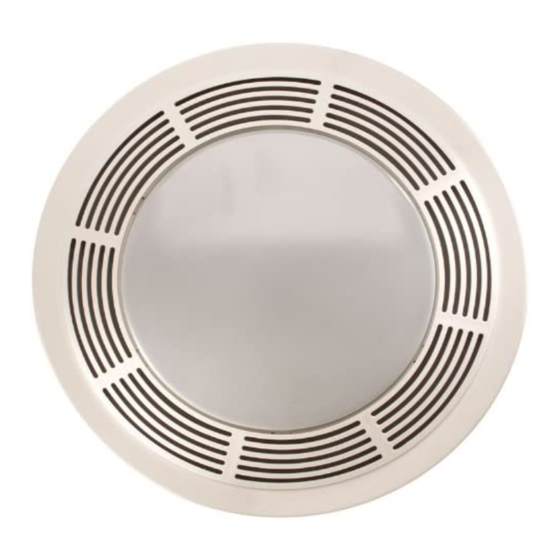
Fan / light combination ventilator
Hide thumbs
Also See for 751:
- Installation instructions manual (8 pages) ,
- Instructions manual (9 pages)
Table of Contents
Advertisement
FAN / LIGHT
COMBINATION VENTILATOR
READ AND SAVE THESE INSTRUCTIONS
W ARNING
TO REDUCE THE RISK OF FIRE, ELECTRIC SHOCK, OR IN-
JURY TO PERSONS, OBSERVE THE FOLLOWING:
1. Use this unit only in the manner intended by the manufacturer.
If you have questions, contact the manufacturer at the address
or telephone number listed in the warranty.
2. Before servicing or cleaning unit, switch power off at service
panel and lock the service disconnecting means to prevent
power from being switched on accidentally. When the service
disconnecting means cannot be locked, securely fasten a promi-
nent warning device, such as a tag, to the service panel.
3. Installation work and electrical wiring must be done by a quali-
fied person(s) in accordance with all applicable codes and stan-
dards, including fire-rated construction codes and standards.
4. Sufficient air is needed for proper combustion and exhausting
of gases through the flue (chimney) of fuel burning equipment
to prevent backdrafting. Follow the heating equipment
manufacturer's guideline and safety standards such as those
published by the National Fire Protection Association (NFPA),
and the American Society for Heating, Refrigeration and Air
Conditioning Engineers (ASHRAE), and the local code authori-
ties.
5. When cutting or drilling into wall or ceiling, do not damage
electrical wiring and other hidden utilities.
6. Ducted fans must always be vented to the outdoors.
7. If this unit is to be installed over a tub or shower, it must be marked
as appropriate for the application and be connected to a GFCI
(Ground Fault Circuit Interrupter) - protected branch circuit.
8. Never place a switch where it can be reached from a tub or
shower.
9. To reduce the risk of electrical shock, do not use this fan with
any solid-state speed control.
10. Not for use in kitchens.
11. Do not install in a ceiling insulated to a value greater than R-40.
12. This unit must be grounded.
!
CAUTION
1. For general ventilating use only. Do not use to exhaust hazard-
ous or explosive materials and vapors.
2. To avoid motor bearing damage and noisy and/or unbalanced
impellers, keep drywall spray, construction dust, etc. off power
unit.
3. Please read specification label on product for further informa-
tion and requirements.
FOR BEST RESULTS
When installing the Exhaust Fan/Light in a new construction site,
install housing during the rough-in construction of the building.
The blower unit, reflector and grille should be installed after the
finished ceiling is in place.
PLANNING DUCTWORK AND WIRING
DUCTWORK
1. Use 4" round duct.
2. Plan duct run from discharge opening of fan to the outside. For
best fan performance, make duct run as short as possible and
use minimum number of elbows.
3. Use optional Broan ducting accessories as needed.
WIRING
Plan to run 120 VAC house wiring (with ground) from power source,
through wall switch, to junction box in housing. For separate con-
trol of fan and light use an optional Broan switch.
IMPORTANT: Use wire suitable for 90
MODEL 751
Page 1
C.
o
Advertisement
Table of Contents

Related Manuals for Broan 751


Summary of Contents for Broan 751
- Page 1 FOR BEST RESULTS through wall switch, to junction box in housing. For separate con- trol of fan and light use an optional Broan switch. IMPORTANT: Use wire suitable for 90 When installing the Exhaust Fan/Light in a new construction site, install housing during the rough-in construction of the building.
-
Page 2: Mounting The Housing
MODEL 751 Page 2 INSTALLATION IN A NEW CONSTRUCTION SITE PREPARATION 1. Refer to Figure 1. Remove power unit/blower assembly from housing. A. Unplug power unit. B. Remove screw (located next to plug-in receptacle) which holds power/blower unit mounting plate in place. Save screw. -
Page 3: Completing Installation
MODEL 751 Page 3 POWER/BLOWER UNIT INST ALLA TION 1. Refer to Figure 1. Place power/blower unit into housing so that mounting plate’s tabs insert into slots in housing. 2. Press other end of mounting plate down until it is firmly seated over scroll and plug-in receptacles. -
Page 4: Service Parts
10034-000 Fan Receptacle state to state. This warranty supersedes all prior warranties. To qualify for warranty service, you must (a) notify Broan-NuTone at the address stated below or 10104-900 Reflector telephone: 1-800-637-1453, (b) give the model number and part identification and (c) describe the nature of any defect in the product or part. -
Page 5: P Ara Obtener Mejores Resul T Ados
Para conseguir el mejor rendimiento del ventilador, haga el conducto lo más corto posible y utilice los menos codos posibles. 3. Utilice los accesorios opcionales de Broan para conductos si los necesita. P ARA OBTENER MEJORES RESUL T ADOS CABLEADO Planee pasar un cableado de la casa de 120v CA (puesto a tierra) desde la fuente de Cuando instale la lámpara/ventilador aspirante en una construcción nueva, instale la... -
Page 6: Montaje De La Caja
MODELO 751 MODEL 751 Page 6 Página 6 INSTALACION EN UN LUGAR NUEVO DE CONSTRUCCION PREPARACION 1. Refiérase a la Figura 1. Saque el conjunto de la unidad de potencia/soplador de la caja. A. Desenchufe la unidad de potencia. B. Quite el tornillo (localizado junto al receptáculo de clavija) que sostiene la placa de montaje de la unidad de potencia/soplador en su sitio. - Page 7 MODELO 751 MODEL 751 Página 7 Page 7 INSTALACION DE LA UNIDAD DE POTENCIA/SOPLADOR 1. Refiérase a la Figura 1. Coloque la unidad de potencia/soplador en la caja para que las lengüetas de la placa de montaje se inserten en las ranuras de la caja.
-
Page 8: Uso Y Cuidado
GARANTIAS IMPLICITAS DE COMERCIALIZACION O APTITUD PARA UN PROPOSITO PARTICULAR. 63007-000 Tuerca empujar Durante el período de un año, y a su propio criterio, Broan-NuTone reparará o reemplazará, sin costo alguno cualquier producto o pieza que se encuentre defectuosa bajo condiciones normales de servicio y uso. 85974-000 Ensamblaje del réflector...