Table of Contents
Advertisement
Quick Links
Download this manual
See also:
Instruction Manual
Advertisement
Table of Contents

Related Manuals for Datavideo PTC-120


Summary of Contents for Datavideo PTC-120
-
Page 2: Table Of Contents
4. Location and Function of Parts ........12 5. Remote Control and On-Screen Menu ....... 15 5.1 Remote Control Functions .......... 15 5.2 Descriptions of Major Functions ......... 16 Switching between PTC-120 devices ......16 Saving current lens position data ........16... - Page 3 Example 2 - Adjust Auto Focus Speed ......28 6. Instruction for installation ..........29 6.1 Preparation before Installation ........29 6.2 Installation of PTC-120 on the desk ......29 6.3 Installation of PTC-120 on the ceiling ......30 7. Frequently-Asked Questions ........36 8.
- Page 4 9.1 OUTPUT Switch ............43 9.2 IR SELECT ..............44 9.3 Camera Address Selector ..........44 9.4 System Switch ............. 45 9.5 Service Switch ............. 46 10. Component Video Output – DSub PIN Assignments ....................47 11. RS-232 PIN Assignments ........... 48 11.1 PIN Descriptions ............
-
Page 5: Warnings And Precautions
This product should only be operated from the type of power source indicated on the marking label of the AC adapter. If you are not sure of the type of power available, consult your Datavideo dealer or your local power company. -
Page 6: Warranty
DVD Drives, Hard Drives are only covered for the first 10,000 hours, or 1 year (whichever comes first). Any second year warranty claims must be made to your local Datavideo office or one of its authorized Distributors before the extended warranty... -
Page 7: Disposal
It must be handed over to the applicable take back scheme for the recycling of electrical and electronic equipment. For more detailed information about the recycling of this product, please contact your local Datavideo office. Packing List 1 x PTC-120 PTZ Camera 1 x Accessory List... -
Page 8: Product Overview
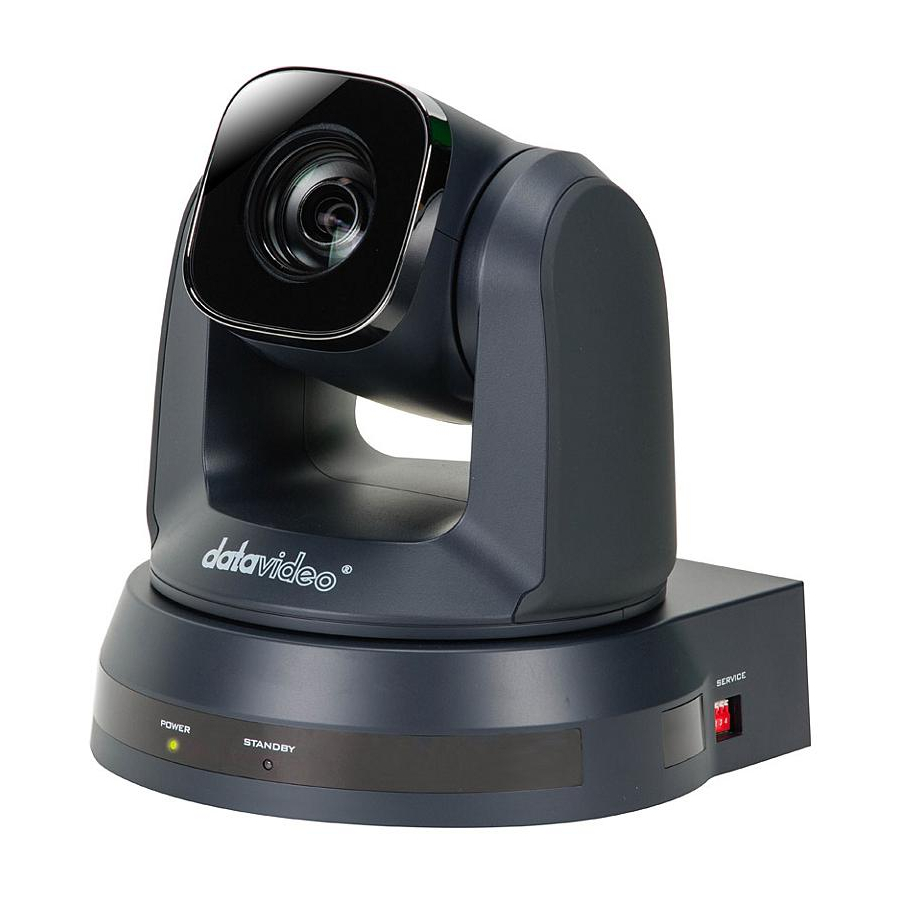
1. Product Overview The Datavideo PTC-120 HD/SD Video Camera is a PTZ camera that can be mounted on a wall, ceiling, floor, or a tabletop, and comes with an IR remote control. The camera is equipped with 1/2.8 inch image sensor •... -
Page 9: Single Camera Connection
3G- SDI, Component, DVI and CVBS. Below scenario diagrams show each of these connections in use with an appropriate cable and monitor/TV. PTC-120 to an HDTV or a computer monitor (DVI) PTC-120 to a TV (Composite Video) (Cable (Cable Optional) -
Page 10: Sony Visca Compatible Controller
SONY VISCA Compatible Controller In addition to the supplied IR remote control, the PTC-120 camera can also be controlled remotely using a SONY VISCA compatible controller such as the Datavideo RMC-190 unit. This camera can be controlled over an RS-232C or RS- 422 connection as shown in the diagrams below. -
Page 11: Multiple Cameras Cascade
3.2 Multiple Cameras Cascade The PTC-120 camera can also be used in an environment where multiple cameras are required. With RS-232 INPUT/OUTPUT ports, the user is allowed to cascade up to seven cameras, which are subsequently controlled by either a computer (Please download a utility program first from http://www.serialporttool.com/PTZ.htm... -
Page 12: Location And Function Of Parts
4. Location and Function of Parts Front of Camera Camera Lens 20x Optical Zoom; 12x Digital Zoom Power LED Indicator No Light: Power off Green: In use Flashing Green: Receiving signal from the remote control; the indicator flashes every 0.5 second Standby LED Indicator Orange: Standby mode No Light: Power on... - Page 13 OUTPUT Switch (Page 40) Set the output resolution. Camera Address Selectors (Page 41) Set the camera address. RS-232C Output Connection of multiple cameras RS-232C Input VISCA Control (Page 52) RS-422 I/O Connection VISCA Control (Page 52) and Connection of multiple cameras Composite VIDEO Output Analog Video Transmission 3G-SDI Output...
- Page 14 Service Switch (Page 43) Service switch is used to set the respective firmware upgrades.
-
Page 15: Remote Control And On-Screen Menu
Press the arrow buttons to pan and tilt the lens Backlight Turn on/off backlight compensation Camera Select Select PTC-120 Cameras 1-3 Focus – To adjust the focus manually, press the Far/Near/Man MANUAL button and adjust the focus with the FAR and NEAR buttons Focus –... -
Page 16: Descriptions Of Major Functions
Press fast to zoom quickly Zoom – Slow Press slow to zoom slowly 5.2 Descriptions of Major Functions Switching between PTC-120 devices Press [Camera 1 ~ 3] on the remote control to select the corresponding PTC- 120 camera. • Camera 1 ~ 3 is selected with IR SELECT (Page 41). -
Page 17: Zoom In/Out Images
Zoom in/out images Adjust image size • Press [Fast +] on the remote control to zoom in images quickly. Press [Fast -] on the remote control to zoom out images quickly. • Fine-tune image size Press [Slow +] on the remote control to zoom in images slowly. •... -
Page 18: On-Screen Menu
5.3 On-Screen Menu On-Screen Menu allows the user to change various camera settings such as shooting conditions and the system setup. Press [Menu] on the remote control to enter the on-screen menu as shown below. On-Screen MENU Exposure • • White Balance •... - Page 19 Gain Limit Gamma Skin Tone Brightness Contrast Black Level Details of all options in the on-screen menu are described in the table below. The bold underlined values are defaults. First Level Second Level Third Level Sub-Option Main Options Sub-Options Parameters Descriptions 1.
- Page 20 6 – 4. Setting Exposure_Comp.Level to 0 is equivalent to disabling exposure compensation. This function can be turned on only when the mode is Spot Light On/Off set to Full Auto or Shutter Pri. The value can be adjusted Spot Light only after Spot Light is X(0~8)Y(0~6) Position...
- Page 21 1/60 1/50 1/30 1/25 1/15 1/12 ½ 0 dB 2 dB 4 dB 6 dB 8 dB 10 dB 12 dB Manually select the gain from 0 dB to 30 dB. Greater 14 dB Manual Gain gain results in brighter images.
- Page 22 30 dB 60/30 50/25 mode mode 1/10000 1/10000 1/5000 1/5000 1/3000 1/3000 1/2500 1/2500 1/2000 1/1750 1/1500 1/1250 1/1000 1/1000 1/725 1/600 1/500 1/425 Manually select the electric shutter speed. Fast shutter 1/350 1/300 Manual Speed results in a darker image and slow shutter results in a 1/250 1/215...
- Page 23 8 dB 10 dB 12 dB 14 dB 16 dB 18 dB The maximum electric gain Gain Limit limit 20 dB 22 dB 24 dB 26 dB 28 dB 30 dB Wide Dynamic WDR Setting Range (WDR) Auto Auto: Adjust the white Indoor balance automatically.
- Page 24 Sodium Lamp 3000K 4300K 5000K 6500K 8300K Wide Auto One Push ENTER One push trigger Trigger Picture effect Set the picture effect B&W Adjust the sharpness of the Sharpness 1~A~16 image Auto Picture 2D NR Set 2D noise reduction Set 3D dynamic noise 3D NR reduction...
- Page 25 Auto Mode1 “Image Mode” option allows the user to apply different Mode2 image settings, such as saturation, hue, gamma, skin Mode3 tone and etc, to the image. Modes 1-6 are fixed and Image Mode Mode4 cannot be changed. If the user would like to customize their own desired image Mode5...
- Page 26 Custom. Adjust the shadow detail Type1 and transparency of the Black Level screen, Adjustable when Type2 Image Mode is set to Custom. Type3 PAN/TILT Turn on/off the angle limit ON/OFF Limit setting PAN Right 0~170 Limit the right angle Limit PAN Left Limit -170~0 Limit the left angle...
-
Page 27: Example 1 - Adjusting Auto Focus Sensitivity
frame, focusing will be on the center of the screen. When full area was set as AF frame, focusing will be calculated based on the full screen. NTSC LB NTSC CP NTSC SQ Composite Image Mode Video (CVBS) PAL LB PAL CP PAL SQ Video Type... -
Page 28: Example 2 - Adjust Auto Focus Speed
set to [Low]. Press [MENU] to activate the on-screen menu. Press [ ] or [ ] to select [Auto Focus]. Press [ENTER] to activate. Press [ ] or [ ] to select [AF Sensitivity]. Press [ENTER] to activate. Press [ ] or [ ] to select [High/Middle/Low]. -
Page 29: Instruction For Installation
6. Instruction for installation 6.1 Preparation before Installation To install PTC-120 by yourself, please follow the steps outlined below to ensure proper installation of the device. Make sure safety precautions are followed to avoid any accident. Ensure the safety of an installation environment. Do not install the device on •... -
Page 30: Installation Of Ptc-120 On The Ceiling
6.3 Installation of PTC-120 on the ceiling Preparation of the parts and equipment required for • installation Accessories of PTC-120 in the box (metal plates A, B and M3 screws) Screw for locking on ceiling mounted hangers Drilling machine, screw driver, ladder ... - Page 31 Size Diagram • Metal plate B - Ceiling Side Metal plate B locking screw Metal plate B locking bolt M3 threaded hole M3 threaded hole M3 threaded hole Metal plate B - Ceiling Side...
- Page 32 Metal plate A - Machine Side Metal plate A - Locking Screw Metal plate A - Machine Side...
-
Page 33: Precautions For Installation
Bottom of Machine Precautions for Installation • Before installation, please confirm the orientation of the device relative to the object to be captured. It is recommended that the device should be set at a distance of more than 1 meter away from the object to be captured. - Page 34 be installed on the ceiling, please use the UL security certified hanger to prevent the device from falling. Please check whether the camera is installed securely on a regular basis. Installation Steps • Please configure the resolution by adjusting the DIP switch first (Please ...
- Page 35 Finally remove the screws on the hanger and the device ...
-
Page 36: Frequently-Asked Questions
7. Frequently-Asked Questions This section describes problems that you may encounter while using PTC-120. If you have questions, please refer to related sections and follow all the suggested solutions. If problem still exists, please contact your distributor or the service center. - Page 37 2. Make sure System Switch (Page 42) DIP1 and DIP3 are correct. R/B Gain and L/R 1. R/B Gain is not an available function on PTC-120. Direction are not functional when 2. Commands of L/R Direction differ from PTC-120 controlling PTC-120 with thus L/R Direction is not functional.
- Page 38 TXD IN- TXD IN+ TXD IN+ How to control multiple Multiple PTC-120 cameras can also be connected in a PTC-120 cameras using daisy chain fashion. The following diagram shows the SONY RM-BR300 user how to cascade multiple PTC-120 cameras with...
- Page 39 Control of PTC-120 The diagram below shows the user how they can using SONY’s RM-BR300 connect SONY’s RM-BR300 Keyboard Controller to the Keyboard Controller on PTC-120 camera via RS-232 interface. RS-232 interface Camera RS-232C SONY RM-BR300 Terminal IR OUT OPEN N.C.
-
Page 40: Specification
8. Specification Video Image Pickup Element 1/2.8 type CMOS sensor Effective Picture Elements Approx. 2.0 Mega pixels Resolution HD / FHD 1080/ 60p , 1080/ 50p , 1080/ 60i, 1080/ 50i, 1080/ 30p, Signal System 1080/ 25p, 720/ 60p, 720/ 50p, 720/ 30p , 720/25p S/N Ratio 50dB Electric Shutter... -
Page 41: Video Output
Pan/Tilt Speed Pan & Tilt : 300°/sec Initialization Time 13 sec Preset 128 Position Coordinate Report Camera ID 1~7 (VISCA) Camera Title Lens Lens Type 20x Optical Zoom, 12x Digital Zoom Focal Length f = 4.7 ~ 94 mm Angle of View (Horizontal) 63°... - Page 42 IR Control One IR controller Others Moving Noise while Tilt <=30dB (Average) Moving Noise while Pan <=30dB (Average) Position Coordination Report 0℃~ 45℃ Operating Temperature -10℃~60℃ Storage Temperature Operating Humidity: 20 % to 80 % (no condensation) Certifications CE / FCC Class A 6.9”...
-
Page 43: Dip Switch
9. DIP Switch PTC-120 offers the user four types of DIP Switch and prior to installation of the device, the user must first configure these DIP switch settings. Please turn off the machine before changing DIP switch setting. The four types of DIP switch... -
Page 44: Ir Select
1920x1080/59.94p 1920x1080/59.94i 1920x1080/29.97p 1280x720/59.94p 1920x720/29.97p 9.2 IR SELECT IR Select assigns the camera an identification number when the user desires to operate multiple cameras using the Remote Control (Page 14). Setting 9.3 Camera Address Selector Camera Address Selector sets the camera address used in the cascade connection scenario. -
Page 45: System Switch
Setting Function Descriptions Addresses are assigned to the cameras automatically in the power- on order. Camera Address 1-7 Reserved 9.4 System Switch System switch adjusts the basic system settings, such as communication protocol, IR signal, and communication baud rate. Setting Function Descriptions DIP 1 RS-232C/RS-422 Selector... -
Page 46: Service Switch
DIP 1 of the System Switch is set to OFF. Camera Address Selector is set to zero. Setting Function Descriptions OFF (Default) Upgrade of Camera DSP FW/Camera Protocol FW/M3 Control FW PAN Motor Firmware Upgrade N.B. Please contact Datavideo’s technical team for firmware upgrade SOP. TILT Motor Firmware Upgrade... -
Page 47: Component Video Output - Dsub Pin Assignments
10. Component Video Output – DSub PIN Assignments Signals Name Red Video GREEN Green Video BLUE Blue Video ID2/RES Reserved Ground (HSync) RED_RTN Red return GREEN_RTN Green return BLUE_RTN Blue return KEY/PWR +5V DC Ground (VSync) ID0/RES Reserved ID1/SDA C Data HSync Horizontal sync VSync... -
Page 48: Rs-232 Pin Assignments
11. RS-232 PIN Assignments 11.1 PIN Descriptions Signals Name Data Transmission Read (Output) Data Set Read (Input) Transmit Data (Output) Ground Receive Data (Input) Ground IR OUT IR Commander Signal (Output) N.C. No Connection... -
Page 49: Wiring Diagrams
11.2 Wiring Diagrams With RS-232 interface, PTC-120 can be controlled using a home PC. The diagram below shows the connection in a PC-controlled scenario. Camera RS-232C PC RS-232C Terminal Terminal IR OUT N.C. -
Page 50: Rs-422 Pin Assignments
12. RS-422 PIN Assignments PTC-120 PTZ control function can be remotely controlled at any location via RS-422 interface 12.1 PIN Descriptions PIN No. Function RXD OUT- RXD OUT+ TXD OUT- TXD OUT+ RXD IN- RXD IN+ TXD IN- TXD IN+... -
Page 51: Physical Connection
12.2 Physical Connection Hold the two sides of RS-422 connector and pull out in the direction indicated by the arrow in the figure below Peel off a section of copper wire (AWG Nos.28 to18) and insert it into the connector hole; use a flat head screwdriver to fix the copper wire in the connector hole with a slotted screw. -
Page 52: Wiring Diagrams
<Note> When RS-422 connection is being used; do not use RS-232C connection. 12.3 Wiring Diagrams To control PTC-120 with an external keyboard controller, establish RS-422 interface connections between PTC-120 and RMC-190 keyboard controller as shown below. RS-422 Interface on PTC-120... -
Page 54: Visca Commands
13. VISCA Commands Command Command Command Comments Packet AddressSet Broadcast 88 30 01 FF Address setting IF_Clear Broadcast 88 01 00 01 FF I/F Clear CommandCancel 8x 2p FF p: Socket No. (=1 or 2) 8x 01 04 00 02 FF Power ON/OFF CAM_Power Off (Standby) - Page 55 Stop 8x 01 04 08 00 FF * Enabled during Manual Mode p=0 (Low) to 7 (High) Far (Standard) 8x 01 04 08 02 FF Near (Standard) 8x 01 04 08 03 FF Far Step 8x 01 04 08 04 FF Near Step 8x 01 04 08 05 FF Far (Variable)
- Page 56 One Push WB 8x 01 04 35 03 FF One Push WB mode 8x 01 04 35 04 FF Auto Tracing White Balance Sodium Lamp 8x 01 04 35 05 FF Sodium lamp source fixed mode 3000K 8x 01 04 35 06 FF Color temperature fixed at 3000K mode 4300K 8x 01 04 35 07 FF...
- Page 57 Reset 8x 01 04 0E 00 FF Exposure Compensation Amount Setting 8x 01 04 0E 02 FF Down 8x 01 04 0E 03 FF 8x 01 04 4E 00 00 0p ExpComp Position, pq: 00 To 0A Direct 8x 01 04 33 02 FF Back Light Compensation ON/OFF *Enabled in AE Full Auto Mode CAM_BackLight...
- Page 58 8x 01 04 62 02 FF Still Image ON/OFF CAM_Freeze 8x 01 04 62 03 FF 8x 01 04 63 00 FF Picture Effect Setting CAM_PictureEffect Neg.Art 8x 01 04 63 02 FF B&W 8x 01 04 63 04 FF 8x 01 04 66 02 FF Picture flip ON/OFF CAM_PictureFlip...
- Page 59 Suppression increases as the level number increases. Direct 8x 01 04 49 00 00 00 pq:0x00~0x19 CAM_ColorGain pq FF (Saturation) CAM_ColorHue Direct 8x 01 04 4F 00 00 00 p: 0x00~0x0E 0p FF 8x 01 06 08 02 FF IR (remote control) receive ON/OFF IR_Receive 8x 01 06 08 03 FF On/Off...
- Page 60 DownLeft W: 0 Pan Limit Position YYYY: FFFF~F52C Tilt Limit Position ZZZZ: FFFF~FE1B 8x 01 06 07 01 0W LimitClear 07 0F 0F 0F 07 0F 0F 0F FF Firmware Firmware version 8x 01 02 03 FF Read Error Code 8x 01 01 01 FF Error Code Clear Error Code...
-
Page 61: Optional Accessory Cables
AE Bright Control (Using EV) 8x 01 04 0D 02 FF CAM_AE_Bright_Ctrl 8x 01 04 0D 03 FF Down 14. Optional Accessory Cables PTC-120 HD/SD PTZ Camera Cable Item Description CB-49 Daisy Chain VISCA / RS-232C male to male control cable 15M CB-50... - Page 62 Notes...
- Page 63 Notes...
-
Page 64: Service & Support
15. Service & Support...