
Related Manuals for Sharp CV10CTXB


Summary of Contents for Sharp CV10CTXB
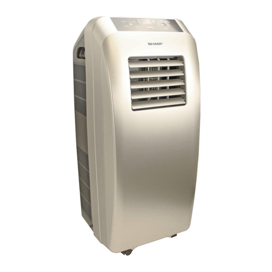
- Page 1 PORTABLE TYPE ROOM AIR CONDITIONER INSTALLATION AND OPERATION MANUAL ACONDICIONADOR DE AIRE PARA HABITACIÓN TIPO PORTÁTIL MANUAL DE INSTALACIÓN Y FUNCIONAMIENTO CV10CTXB CV10CTXW CV10CTXS...
-
Page 3: Declaration Of Conformity
• TIMER OPERATION ................EN-21 • SLEEP OPERATION ................EN-22 • MAINTENANCE ................... EN-23 • BEFORE CALLING FOR SERVICE ............EN-25 Declaration of Conformity SHARP ROOM AIR CONDITIONER CV10CTXB, CV10CTXW, CV10CTXS This device complies with Part 18 of FCC rules. Responsible Party: SHARP ELECTRONICS CORPORATION. Sharp Plaza, Mahwah, New Jersey 07495-1163... - Page 4 MODEL NUMBER SERIAL NUMBER DATE OF PURCHASE Dealer Name Address City State Telephone TO PHONE: Dial 1-800-BE-SHARP (237-4277) for: SERVICE (for your nearest Sharp Authorized Servicer) PARTS (for your Authorized Parts Distributor) ACCESSORIES ADDITIONAL CUSTOMER INFORMATION TO WRITE: For service problems, warranty information, missing items and other assistance: Sharp Electronics Corporation Customer Assistance Center...
- Page 5 Sharp to the purchaser with respect to the Product, and shall constitute full satisfaction of all claims, whether based on contract, negligence, strict liability or otherwise. In no event shall Sharp be liable, or in any way responsible, for any damages or defects in the Product which were caused by repairs or attempted repairs performed by anyone other than an authorized servicer.
- Page 6 PRECAUTIONS Points to keep in mind when using your unit. WARNINGS FOR USE • Install the unit in accordance with the installation instructions in the latter section of this manual. • Do not modify any part of this product. • Do not insert anything into any part of the unit. • Ensure the power supply used has an appropriate voltage rating. Only use a three-pin grounded electrical AC socket rated 125V, 60Hz, and 15 amps or more. Use of a power supply with an improper voltage rating can result in damage to the unit and possibly fire. • Always use a fuse with the proper amp rating. Do not, under any circumstances, use wire, pins or other objects in place of a proper fuse.
- Page 7 WARNING ABOUT GROUNDING • Improper use of the grounding plug can 3-Pin socket result in the risk of electric shock. This appliance must be grounded. In the event of an electrical short circuit, ground- Grounding pin ing reduces the risk of an electric shock by providing a less resistant conduit for the 3-Pin plug electric current.
-
Page 8: Operating Conditions
PRECAUTIONS NOTES ON OPERATION • Allow 3 minutes for the compressor to restart cooling. If you turn the unit off and immediately restart it, allow three minutes for the compressor to restart cooling. There is an electronic device in the unit that keeps the compressor turned off for three minutes for safety. • In the event of a power failure during use, allow 3 minutes before restarting the unit. -
Page 9: Location
LOCATION • The unit should be placed on a firm foundation to minimize noise and vibration. For safe and secure positioning, place the unit on a smooth, level floor strong enough to support MIN.12" the unit. MIN.12" (30cm) • The unit has casters to aid placement, but it should only be (30cm) rolled on smooth, flat surfaces. Use caution when rolling on carpet surfaces. Do not attempt to roll the unit over objects. - Page 10 STRUCTURE 1 Control panel and display lamp 2 Remote control signal receiver window Front 3 Handle 4 Remote controller box 5 Air outlet 6 Vertical louvers 7 Horizontal louvers 8 Wheel 9 Air inlet 10 Grill 11 Air outlet 12 Air inlet 13 Power cord hook 14 Power cord 15 Window exhaust adapter (down)
- Page 11 INSTALL POWER CORD HOOK • Attach the hooks to the back of air conditioner with the screws. hook screw • When storing or moving the unit, wind the power cord around the hooks. EN-9...
-
Page 12: Install Drainage Hose
INSTALL DRAINAGE HOSE Drainage hose must be installed before using, otherwise blockage of drain may occur and normal run of unit may be affected. 1 Remove drain cap from drain port. 2 Attach the drain hose clamp to the back panel of the air conditioner near the drain port with the screw. A. Drain cap A. Drain port B. Drain port... - Page 13 When COOL or DRY (DEHUMIDIFICATION) is running, condensation will drain to water tank. When water tank is filled, Buzzer will sound 8 times, LED window show error code "H8". In this case, plug out drain hose from fixing clamp,unsecure the clip, pull out the rubber plug from the drain hose, then drain out water in tank. Then reinstall the drainage hose. The unit will resume running after compressor stops for 3 minutes. A. Drain port B. Drain hose clamp EN-11...
-
Page 14: Install Window Panel
INSTALL WINDOW PANEL Installation in a double-hung sash window Hole Insect guard net Rain guard Connect the rain guards to the insect guard net. Insert all three projections on each rain guard into the holes in the insect guard net. Side “A” will now be at the top, as indicated in the diagram. - Page 15 If the inner width of the window is between 24"(609mm) and 36.8"(934mm) inclusive. (1) Open the window sash and place the window panel on the window sill. (2) Slide the adjustment panel to fit the window frame width. 24"-36.8" (3) Secure the window panel to the sill with 3 screws. If the inner width of the window is between 36.8"(934mm) and 48"(1219mm) inclusive.
- Page 16 INSTALL WINDOW PANEL Installation in a sliding sash window "A" Connect the rain guards to the insect guard net. Insert all three projections on each rain guard into the holes in the insect guard net. Insect guard net Side “A” will now be at the top, as indicated in the diagram. Hole Projection Attach the guard combined above to...
- Page 17 If the inner width of the window is between Adjustment panel 24"(609mm) and 36.8"(934mm) inclusive. (1) Open the window sash and place the window panel on the window sill. (2) Slide the adjustment panel to fit the window frame width. (3) Secure the window panel to the sill 24"- 36.8" with 3 screws.
-
Page 18: Installation And Removal Of Exhaust Hose
INSTALLATION AND REMOVAL OF EXHAUST HOSE Installation of the exhaust hose Window exhaust adapter Attach the window exhaust adapter B and C to the exhaust hose. Extend both ends of the exhaust hose and insert them into the window ex- haust adapter A respectively, and turn Exhaust hose them until they stop. - Page 19 Removal of the exhaust hose Remove the exhaust hose from the window exhaust adapter. Exhaust hose window exhaust adapter Remove the window exhaust adapter A from the unit. Lift up and remove the window exhaust adapter A from the unit by pushing down on the two projections.
-
Page 20: Control Panel & Display
CONTROL PANEL DISPLAY & OPERATING INSTRUCTIONS CONTROL PANEL & DISPLAY Temperature selection button LED window COOL mode lamp Receiver window mode lamp MODE button FAN Speed lamp ON/OFF button FAN mode lamp Fan speed button OPERATING INSTRUCTIONS When pressing key, buzzer makes a sound, indicator lamp shows relevant state for 2 seconds. ON/OFF Button Press the button once to manually turn the unit on. - Page 21 Point the remote control towards the units signal receiver window and press the desired button. A beep will sound when the unit receives the signal. • Make sure nothing, such as curtains, blocks the signal receiver window. • For good reception of signal, the distance between operator and the unit should be no more than 5 meters.
- Page 22 OPERATION OF WIRELESS REMOTE CONTROL Notice: This is a general use remote controller, it could be used for the air conditioners with multifunction. • Names and functions of wireless remote control Note: Be sure that there are no obstructions between receiver and remote controller; Don't drop or throw the remote control; Don't let any liquid in the remote control and put the remote control directly under the sunlight or any place where is very hot. Signal transmitter T-ON T-OFF AUTO...
- Page 23 TIMER TIMER button T-ONT-OFF AUTO • By pressing this key under switch-off state, COOL SLEEP LOCK you may set the time for auto switch-on. The SPEED range of setting is 0.5 ~ 24 hours. The characters "T-ON" and "H" will flash for 5 ON/OFF MODE seconds.
- Page 24 OPERATION OF WIRELESS REMOTE CONTROL Guide for operation- General operation 1. After powered on, press ON/OFF button, the unit will start to run. 2. Press MODE button, select desired running mode, enter into the corresponding operation directly. ON/OFF MODE 3. Pressing + or - button, to set the desired temperature. (It is unnecessary set the temp. at AUTO mode.) 4. Pressing FAN button, set fan speed, can select AUTO, FAN 1, FAN 2, FAN 3 or FAN 4. (Note: SLEEP TIMER...
- Page 25 MAINTENANCE • Changing batteries and notices Slightly to press the place to take out the back cover of wireless remote control.(As shown in figure) Take out the old batteries. (As show in figure) Insert two new AAA1.5V dry batteries, and pay attention to the polarity. (As show in figure) Attach the back cover of wireless remote control. (As show in figure NOTE: • When changing the batteries, do not use old or different batteries, otherwise, it can cause the malfunction of the wireless remote control.
- Page 26 MAINTENANCE Mobile AC There are wheels at bottom of mobile air conditioner that enable the unit moves among rooms conveniently according to need. Warning Plug off power plug from socket and cut off power before any maintenance to prevent electric shock or damage to units. Clean air filter If too much dust collected on filter, performance of air conditioner will reduce, thus it is better to clean filter at least once 2 weeks.
-
Page 27: Troubleshooting
MALFUNCTION ANALYSIS If malfunction occur, please check the following before maintenance: Troubles Possible Causes Solutions The air conditioner The power supply is not 1. Insert the power plug tightly. doesn't start. connected well. 2. Replace the power plug or The power plug is not inserted socket. - Page 28 SAFETY NOTICE Location Don't place the unit in narrow location. Guarantee better ventilation for unit to prevent malfunction occurs. Don't place the unit in where there is direct sunburn to prevent fade and reduce of effect. The unit should be at least 50cm away from surface of flammable thing. Don't soak the unit or operateit in place where is easyto get wet to prevent creepage. Don't operate the unit in following location for malfunction may be led: *Gas place *Fire* where is easy to get oil. Others: Consider safe problem to following people. 1) Children and patients. 2) Sick people or who cannot express himself or herself. 3) Those who are exhausted, badly drunk or taken lot of soporific. Don't climb on the unit or place something on it for drop may occur and leading malfunction. Don't let wind blows to human directly for long time for it is not good for health. The unit should leave TV for at least l m to prevent disturbance of electromagnetic wave. Don't block air inlet or outlet vent for it would lead malfunction. Don't insert finger or stick etc. into air outlet vent; take special care to children to prevent accidence. It is forbidden to slope or turn down air conditioner. Take off power plug immediately if abnormal circumstance occurs and contact the authorized seller for check and repair.
- Page 29 MALFUNCTION ANALYSIS For disposal there are several possibilities: a) The municipality has established collection systems, where electronic waste can be disposed of at least free of charge to the user. b) When buying a new product, the retailer will take back the old product at least free of charge. c) The manufacturer will take back the old appliance for disposal at least free of charge to the user. d) As old products contain valuable resources, they can be sold to scrap metal dealers. Wild disposal of waste in forests and landscapes endangers your health when hazardous substances leak into the ground-water and find their way into the food chain. DISPOSAL: Do not dispose this product as unsorted municipal waste.
- Page 30 EN-28...
- Page 31 • MANTENIMIENTO ................ES-23 • ANTES DE LLAMAR AL DEPARTAMENTO DE SERVICIO TÉCNICO ..ES-25 Declaración de Conformidad ACONDICIONADOR DE AIRE PARA HABITACION CV-2P10SC Este dispositivo cumple con la Parte 18 del reglamento de la FCC Parte Responsable: SHARP ELECTRONICS CORPORATION. Sharp Plaza, Mahwah, New Jersey 07495-1163 TEL: 1-800-BE-SHARP ES-1...
- Page 32 NÚMERO DE SERIE FECHA DE COMPRA Nombre del distribuidor Dirección Ciudad Estado Código postal Teléfono LLAMADAS: Marque el 1-800-BE-SHARP (237-4277) para: SERVICIO (para su centro de servicio autorizado Sharp más cercano) PIEZAS (para su distribuidor autorizado de piezas) ACCESORIOS INFORMACIÓN ADICIONAL PARA LOS CLIENTES CORRESPONDENCIA: Sobre problemas de servicio, información de garantía, ítems perdidos y otras ayudas:...
- Page 33 En ninguna circunstancia Sharp será responsable por cualquier daño o defectos en el Producto, causados por reparaciones o intentos de reparaciones hechos por cualquier persona, excepto los centros de sercicio autorizados por Sharp.
- Page 34 PRECAUCIONES Aspectos a tener en cuenta al utilizar el acondicionador de aire. ADVERTENCIAS PARA EL USO • Instale la unidad de acuerdo a las instrucciones de instalación que se describen más adelante en este manual. • No modifique ninguna de las piezas de este producto. • No introduzca nada en ninguna parte de la unidad. • Asegúrese de que el suministro de energía utilizada tiene un voltaje nominal apropiado. Utilice sólo una toma de tres patas conectado a tierra de corriente alterna nominal 125 V, 60 Hz y 15 amperios o más. El uso de una fuente de alimentación con un voltaje incorrecto puede provocar daños a la unidad y posiblemente fuego.
- Page 35 ADVERTENCIA ACERCA DE LA CO- Clavija de 3 NEXIÓN A TIERRA Contacto de contactos tierra • El uso inadecuado de la clavija de co- nexión a tierra puede provacar el riesgo de descargas eléctricas. Este aparato debe de ser conectado a tie- rra.
-
Page 36: Condiciones De Funcionamiento
PRECAUCIONES OBSERVACIONES SOBRE EL FUNCIONAMIENTO • Deje que pasen 3 minutos para que el compresor reanude el enfriamiento. Si apaga la unidad y la enciende inmediatamente después, deje que pasen tres minutos para que el compresor reanude el enfriamiento. Hay un dispositivo electrónico de la unidad que mantiene el compresor desactivado durante tres minutos por seguridad. • Si sucede un fallo de energía durante el uso, deje que pasen 3 minutos antes de reiniciar la unidad. Después de que se reinstale la energía, reinicie el acondicionador de aire. Si la energía ha estado desactivada menos de tres minutos, asegúrese de esperar por lo menos tres minutos antes de rei- niciar la unidad. - Page 37 UBICACIÓN • La unidad se debe colocar sobre una base firme para minimizar los ruidos y las vibraciones. Para lograr una posición segura y protegida, coloque la unidad sobre un piso liso y nivelado, suficientemente fuerte como para soportar el peso. MÍN. 12"...
- Page 38 ESTRUCTURA 1 Lámpara de la pantalla y panel de control 2 Ventana receptora de señal de control remoto Vista frontal 3 Manija 4 Almacenamiento del control remoto 5 Salida de aire 6 Rejillas verticales 7 Rejillas horizontales 8 Rueda 9 Toma de aire 10 Parrilla 11 Salida de aire 12 Toma de aire 13 Gancho para el cable...
- Page 39 INSTALACIÓN DEL GANCHO PARA EL CABLE DE SUMINISTRO DE ENERGÍA • Instale los ganchos en la parte trasera del acondicionador de aire con los tornillos. Gancho Tornillo • Cuando guarde o traslade la unidad, enrolle el cable de suministro de energía alrededor de los ganchos. ES-9...
- Page 40 INSTALACIÓN DE LA MANGUERA DE DRENAJE La manguera de drenaje se debe instalar antes del uso; de lo contrario, se puede obstruir el drenaje y es posible que el funcionamiento normal de la unidad se vea afectado. 1 Retire la tapa de drenaje de la lumbrera de drenaje. 2 Instale la abrazadera de la manguera de drenaje en el panel trasero del acondicionador de aire cerca de la lumbrera de drenaje con el tornillo.
- Page 41 Cuando la unidad esté funcionando en los modos COOL (ENFRIAR) o DEHUMIDIFI- CATION (DESHUMIDIFICACIÓN), la condensación se drenará al depósito de agua. Cuando el depósito de agua esté lleno, el indicador sonoro zumbará 8 veces y la ventana de la pantalla LED mostrará el código de error "H8". En este caso, desenchufe la manguera de drenaje de la abrazadera de fijación, de- sprenda el broche, retire el tapón de caucho de la manguera de drenaje y, después, vacíe el agua del depósito. Luego, vuelva a instalar la manguera de drenaje. La unidad reanudará el funcionamiento después de que el compresor se detenga durante 3 minutos. A. Lumbrera de drenaje B.
- Page 42 INSTALACIÓN DEL PANEL DE VENTANA Instalación en una ventana de guillotina Protector Red de protección doble colgante Agujero contra la contra insectos lluvia Conecte los protectores contra la lluvia a la red de protección contra insectos. Inserte las tres salientes en cada protector contra la lluvia dentro de los agujeros en la red de protección contra insectos.
- Page 43 Altura interior de la ventana: 24" (609 mm) - 36.8" (934 mm) (1) Abra la hoja de la ventana y coloque el panel de ventana sobre el marco. (2) Deslice el panel de ajuste para fijar la altura del marco de la ventana. (3) Fije con 3 tornillos el panel de ventana 24"-36.8"...
- Page 44 INSTALACIÓN DEL PANEL DE VENTANA Instalación en una ventana "A" de guillotina corrediza Conecte los protectores contra la lluvia a la red de protección contra insectos. Red de protección Inserte las tres salientes en cada protector contra insectos contra la lluvia dentro de los agujeros en la Agujero red de protección contra insectos.
- Page 45 Si la altura interna de la ventana es de 24" Panel de ajuste (609 mm) a 36.8" (934 mm) inclusive: (1) Abra la guillotina de la ventana y coloque el panel de ventana sobre el marco de la ventana. (2) Deslice el panel de ajuste para adaptarlo a la altura del marco de la ventana. (3) Asegure el panel de ventana al marco de la ventana con 3 tornillos y 3 escuadras 24"- 36.8"...
- Page 46 INSTALACIÓN Y EXTRACCIÓN DE LA MANGUERA DE ESCAPE Instalación de la manguera de escape Adapatador de ventana Instale la adaptador de ventana y la adaptador A del escape de ventana en la manguera de escape. Extienda ambos extremos de la manguera de escape e insértelos en los adaptadores del escape de ventana Manguera de escape A y B respectivamente; gírelos hasta que se detengan.
- Page 47 Extracción de la manguera de escape Desmonte el adaptador de la manguera de escape de la adapatador de ventana. Manguera de escape Adapatador de ventana Retire el adaptador A del escape de ventana de la unidad. Levante y retire el adaptador A del escape de ventana de la unidad presionando sobre las dos proyecciones.
-
Page 48: Instrucciones De Funcionamiento
PANTALLA DEL PANEL DE CONTROL E INSTRUCCIONES DE FUNCIONAMIENTO PANEL DE CONTROL Y PANTALLA Luz del modo Botón de selección de temperatura Ventana de LED Ventana receptora COOL (ENFRIAR) Luz del modo DRY (DESHUMIDIFICACIÓN) Botón ON/OFF Botón MODE (MODO) Luz de FAN Speed (ENCENDIDO/APAGADO) Luz del modo (Velocidad del ventilador) - Page 49 Oriente el control remoto hacia la ventana receptora de señal de la unidad y presione el botón deseado. Sonará un pitido cuando la unidad reciba la señal. • Asegúrese de la ventana receptora de señal no tenga obstrucciones (como cortinas). • Para lograr una buena recepción de la señal, la distancia entre el operador y la unidad no debe superar los 5 metros.
- Page 50 FUNCIONAMIENTO DEL CONTROL REMOTO INALÁMBRICO Aviso: Este es un control remoto de uso general; se puede usar para acondicionadores de aire con multifunción. • Nombres y funciones del control remoto inalámbrico Nota: Asegúrese de que no haya obstrucciones entre el receptor y el control remoto. No deje caer ni arroje el control remoto. No permita que penetren líquidos en el control remoto y no lo deje bajo la luz solar directa o en lugares con temperaturas muy altas.
- Page 51 TIMER (TEMPORIZADOR) Botón TIMER (TEMPORIZADOR) (T-ENCENDIDO) (T-APAGADO) T-ON T-OFF AUTO (AUTOMÁTICO) • Si se presiona esta tecla en estado apagado, se puede ajustar COOL (ENFRIAR) SLEEP (SUSPENDER) (DESHUMIDIFICADOR) LOCK (BLOQUEO) el tiempo para el encendido automático. Rango de ajuste: 0.5 a (VENTILADOR) SPEED (VELOCIDAD)
- Page 52 FUNCIONAMIENTO DEL CONTROL REMOTO INALÁMBRICO Guía para el funcionamiento. Funcionamiento general 1. Después del encendido, presione el botón ON/OFF (ENCENDIDO/APAGADO); la unidad comenzará a funcionar. 2. Presione el botón MODE (MODO), seleccione el modo de funcionamiento deseado e ingrese directamente a la operación correspondiente. ON/OFF MODE 3. Presione los botones + o - para ajustar la (ENCENDIDO/APAGADO) (MODO) temperatura deseada. (No es necesario ajustar la temperatura en el modo AUTO [AUTOMÁTICO]).
- Page 53 MANTENIMIENTO • Cambio de baterías y avisos Presione ligeramente en el lugar para retirar la cubierta trasera del control remoto inalámbrico (como se muestra en la figura). Retire las baterías usadas (como se muestra en la figura). Inserte dos baterías AAA de 1.5 V secas nuevas; preste atención a la polaridad (como se muestra en la figura). Instale la cubierta trasera del control remoto inalámbrico (como se muestra en la figura).
- Page 54 MANTENIMIENTO Acondicionador de aire móvil En la parte inferior del acondicionador de aire móvil, hay ruedas que permiten mover la unidad entre habitaciones de manera conveniente y de acuerdo con las necesidades. Advertencia Desenchufe la toma de corriente del enchufe de pared y corte la electricidad antes de realizar cualquier trabajo de mantenimiento para prevenir choques eléctricos o daños en la unidad.
- Page 55 ANÁLISIS DE DESPERFECTOS Si se observa mal funcionamiento, compruebe lo siguiente antes de realizar trabajos de mantenimiento: Problemas Posibles causas Soluciones El acondicionador La alimentación eléctrica no 1. Inserte firmemente la toma de aire no arranca. está bien conectada. de corriente. La toma de corriente no está 2.
- Page 56 AVISO DE SEGURIDAD Ubicación No coloque la unidad en un lugar estrecho. Para evitar el mal funcionamiento, asegúrese de que la unidad tenga una buena ventilación. Para evitar la pérdida y la reducción del efecto, no coloque la unidad donde haya luz solar directa. La unidad debe estar alejada al menos 50 cm de superficies de elementos inflamables. No sumerja la unidad y no la haga funcionar en lugares donde podría mojarse fácilmente para evitar fugas eléctricas.
- Page 57 ANÁLISIS DE DESPERFECTOS Existen varias posibilidades para la eliminación de acondicionadores de aire: a) La municipalidad ha establecido sistemas de recolección donde se pueden eliminar desechos electrónicos sin cargo para el usuario. b) Cuando se compra un producto nuevo, el minorista toma el producto usado sin cargo. c) El fabricante toma el electrodoméstico usado para desecho sin cargo para el usuario.
- Page 58 ES-28...
- Page 60 SHARP ELECTRONICS CORPORATION Sharp Plaza, Mahwah, New Jersey 07495-1163 U.S.A SHARP CORPORATION 66129911093...