Table of Contents
Advertisement
[1]
SPECIFICATION.................................... . ....... 1-1
[2]
ELECTRICAL PARTS ............................ . ....... 1-1
[3]
WIRING DIAGRAM ................................ . ....... 1-2
[4]
EXTERNAL DIMENSION....................... . ....... 1-2
[1]
PART NAMES ........................................ . ....... 2-1
[2]
LOCATION ............................................. . ....... 2-2
[3]
INCLUDED............................................. . ....... 2-3
[4]
INSTALL WINDOW PANEL ................... . ....... 2-3
[5]
HAUST HOSE........................................ . ....... 2-4
[6]
PRE-OPERATION CHECKS.................. . ....... 2-5
[7]
OPERATION MODE .............................. . ....... 2-5
[8]
DRAINAGE ............................................ . ....... 2-7
[9]
MAINTENANCE ..................................... . ....... 2-7
[1]
PROCEDURE FOR DISASSEMBLY ..... . ....... 3-1
[2]
DISASSEMBLING THE CONTROL BOX . ....... 3-9
Parts marked with "
" are important for maintaining the safety of the set. Be sure to replace these parts with specified ones for
maintaining the safety and performance of the set.
SERVICE MANUAL
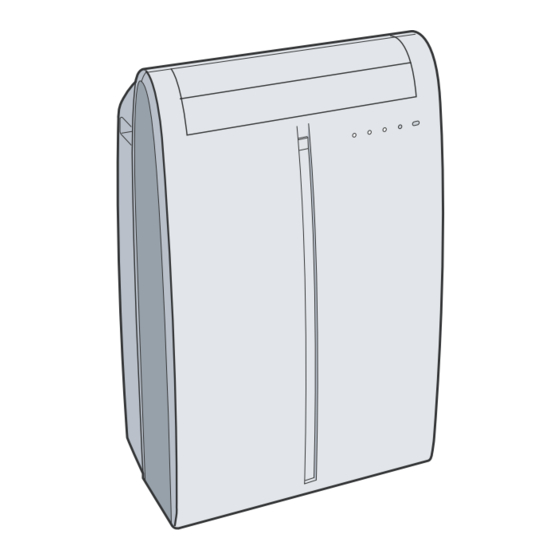
PORTABLE AIR CONDITIONER
CONTENTS
SHARP CORPORATION
CV-P09FX
MODEL
In the interests of user-safety (Required by safety regulations in some countries)
the set should be restored to its original condition and only parts identical to
those specified should be used.
[1]
GRAM............................................................4-1
[2]
PRINTED WIRING BOARD...........................4-2
[3]
FUNCTION ....................................................4-3
[4]
PERFORMANCE CURVES...........................4-6
[1]
HOW TO REPAIR REFRIGERATION ...........5-1
[2]
ELECTRICAL COMPONENT TEST ..............5-3
[1]
TROUBLESHOOTING ..................................6-1
This document has been published to be used
for after sales service only.
The contents are subject to change without notice.
CVP09FX
S3503CVP09FX/T
Advertisement
Table of Contents

Related Manuals for Sharp S3503CVP09FX/T


Summary of Contents for Sharp S3503CVP09FX/T
-
Page 1: Table Of Contents
CVP09FX SERVICE MANUAL S3503CVP09FX/T PORTABLE AIR CONDITIONER CV-P09FX MODEL In the interests of user-safety (Required by safety regulations in some countries) the set should be restored to its original condition and only parts identical to those specified should be used. -
Page 2: Chapter 1. Product Specification
CVP09FX CVP09FX Service Manual CHAPTER 1. PRODUCT SPECIFICATION [1] SPECIFICATION Cooling Capacity BTU/h 9000 Moisture Removal Pint/h Electrical Data Phase Single Rated frequency Rated voltage Rated current Rated input 1010 Power factor BTU/Wh Compressor Type (Hermetically sealed rotary type) Model, Motor Output 44R211AE-AJS (805W) REFRIGERANT SYSTEM Evaporator... -
Page 3: Wiring Diagram
CVP09FX [3] WIRING DIAGRAM [4] EXTERNAL DIMENSION 18.5" Max. : 59" 15.1" 16.1" 1 – 2... -
Page 4: Chapter 2. Operation Instruction Part Names
CVP09FX CVP09FX Service Manual CHAPTER 2. OPERATION INSTRUCTION [1] PART NAMES 1. Front view Air Outlet Vertical louvers Horizontal louvers PLASMACLUSTER Lamp (blue) Remote control signal receiver window AUX. Button OPERATION Lamp (red) TIMER Lamp (orange) MEGA COOL Lamp (green) Air inlet 2. -
Page 5: Location
CVP09FX 3. Remote control Transmitter Display POWER Button LIGHTS Button TEMPERATURE Button PLASMACLUSTER Button 1 hr OFF Button MODE Button ON TIMER Button FAN Button OFF TIMER Button CANCEL Button LOUVERS Button RESET Button MEGA COOL Button 4. Remote control display MODE SYMBOLS : COOL : DEHUMIDIFICATION... -
Page 6: Included
CVP09FX [3] INCLUDED Exhaust hose (1) Window exhaust adapter (1) Bracket (1) Drainage Grommet (1) Exhaust cover (1) Extension panel (1) Adjustment panel (1) Window panel (1) Foam seal (3) Foam seal (1) Rain guard (2) Insect guard net (1) Foam seal (1) (adhesive type)A (adhesive type)B... -
Page 7: Installation And Removal Of Exhaust Hose
CVP09FX Installation in a sliding sash window If the inner height of the window is between 24" (609mm) and 36.8" (See page 12 for installation in a double-hung window.) (934mm) inclusive. Adjustment panel "A" (1) Open the window sash and place the window panel on the window frame. -
Page 8: Pre-Operation Checks
CVP09FX [6] PRE-OPERATION CHECKS POWER PLUG CHECK HOW TO USE THE REMOTE CONTROL This air conditioner uses a fused power plug. Point the remote control towards the units signal receiver window and Always check the power plug before use. RESET press the desired button. -
Page 9: Fan Mode
CVP09FX 3. Fan mode 6. Plasmacluster operation In this mode, the air conditioner simply circulates the air without cooling it. The Plasmacluster ion generator inside the air conditioner will release positive and negative Plasmacluster ions into the room. Approximately the same numbers of posi- Install the exhaust hose (See Page16), turn the drainage nozzle to the CLOSE tive and negative ions released into the air. -
Page 10: Drainage
CVP09FX 9. Timer operation [8] DRAINAGE 9.1. Off timer Prepare for drainage and drain out water within the unit in the following cases. If the unit stops operating and the TIMER, OPERATION and MEGA COOL lamps are The unit will turn off automatically according to your setting. blinking. -
Page 11: Chapter 3. Disassembling Procedure
CVP09FX CVP09FX Service Manual CHAPTER 3. DISASSEMBLING PROCEDURE [1] PROCEDURE FOR DISASSEMBLY "ACTUAL UNITS MAY VARY SLIGHTLY FROM THOSE PICTURES BELOW" CAUTION: • DISCONNECT THE PORTABLE TYPE ROOM AIR CONDITIONER • DISCONNECT THE EXHAUST HOSE FROM THE UNIT BEFORE A •... - Page 12 CVP09FX 5. Push down the orifice (at position of illustration), as shown in below 7. Unscrew 6 screws holding the side panel L and R. figure, to unhook 2 hooks of front panel. Remove side panel L and R. 8. Remove the stopcock from the drainpipe nozzle. 6.
- Page 13 CVP09FX 10.Remove the cabinet by lifting it up and pulling toward you as shown 13.Unscrew 2 screws holding the float switch ass’y. in below figure. Then move the float switch a little from bulkhead L. 11.Unscrew 4 screws holding the control box cover. 14.Unscrew 6 screws holding the bulkhead L.
- Page 14 CVP09FX 15.Unscrew 7 screws holding the stay angle L. 19.Remove the plasmacluster unit and cluster cover. Remove the stay angle L. Disconnect the connector of plasmacluster unit. 20.Unscrew 5 screws holding the top duct Remove the top duct 16.Unscrew 3 screws holding the led guide. Remove the led guide.
- Page 15 CVP09FX 22.Cut the fixing band holding the wires.(7 parts) 24.Cut the fixing band holding the wire and tape. Disconnect 8 connectors. Then remove the tape. CAUTION: CONNECT THE CONNECTORS OF FAN MOTOR ETC. CAUTION: KEEP THE TAPE IN CASE OF RE-ASSEMBLYING. CORRECTLY WHEN RE-ASSEMBLYING.
- Page 16 CVP09FX 28.Unscrew 2 screws holding the control box. 31.Move the band to the direction shown in below figure (approx.11/ 16"). Remove the control box from the unit. Then removed the drain hose B. 32.Unscrew the screw holding the lead wire. 29.Unscrew 6 screws holding the casing cover.
- Page 17 CVP09FX 34.Unscrew 4 screws holding the half plate. 36.Unscrew 6 screws holding the stay angle R. Remove the stay angle R from the unit. 37.Unscrew 3 screws holding the drain pump ass’y. Remove the drain pump ass’y from the unit. Then remove the half plate by lifting it up and pulling toward you as shown in below figure.
- Page 18 CVP09FX 40.Unscrew 4 screws holding the motor cover and wire holder. 43.Remove the 2 motor cushions on each side. Remove the motor cover. Then remove the fan motor. 44.Loosen 2 screws holding the motor cover B. * Do not remove 2 screws and 2 nuts. 41.Unscrew the screw holding the centrifugal fan.
-
Page 19: Disassembling The Control Box
CVP09FX [2] DISASSEMBLING THE CONTROL BOX CAUTION: DISCHARGE THE FAN MOTOR CAPACITOR AND RUNNING CAPACITOR BEFORE TOUCHING THESE CAPACITORS OR OTHER COMPONENTS OR WIRING. 1. Cut fixing bands holding the wires.(2 parts) 2. Remove 2 P.W.B. 3. Cut fixing bands holding the wires.(2 parts) Disconnect 6 connectors. -
Page 20: Chapter 4. Explanation Of Circuit And Operation
CVP09FX CVP09FX Service Manual CHAPTER 4. EXPLANATION OF CIRCUIT AND OPERATION [1] ELECTRONIC CONTROL CIRCUIT DIAGRAM 4 – 1... -
Page 21: Printed Wiring Board
CVP09FX [2] PRINTED WIRING BOARD 4 – 2... -
Page 22: Function
CVP09FX [3] FUNCTION Indoor fan speed Customer Setting 1. Cool Operation Evaporator Temperature AUTO In the "COOL" mode, the thermostat circuit is controlled by 3 thermo- Lower than D3 stat lines(C1~C3). Higher than D3 When the difference between Room Temperature and Preset Temper- 53.6 / 60.8°F ature is in [2]~[4] area, compressor is driving or starts driving. - Page 23 CVP09FX 7. Freeze preventive 8.3. ONE-HOUR TIMER When ONE-HOUR timer is set, the unit turns off automatically after When the indoor pipe temperature falls below 32.0°F during cool oper- one hour. The one hour timer operation has priority over other time ation or dry operation, the compressor is turned off.
- Page 24 CVP09FX 14. SELF-CHECK MODE Louver Louver (Upper Side) (Lower Side) YELLOW GREEN BLUE Room Temp Eva Temp Cond Temp Test Input 44.6~107.6°F 28.4~113.0°F 28.4~113.0°F P37 = H ~44.6°F, ~28.4°F, ~28.4°F, P37 = L 107.6°F~ 113.0°F~ 113.0°F~ Power On Start Function Select A Function Select B Select P44 = H...
-
Page 25: Performance Curves
CVP09FX [4] PERFORMANCE CURVES NOTE: 1) Use this data only as a guide to check the running condition. 2) The running conditions of this data is as follows. Remote control setting ..High cool, 64°F Drain pump ......OFF Exhaust hose ......Shortest 3) This data will be changed by operation conditions such as: a drain pump operation or an exhaust hose configuration. -
Page 26: Chapter 5. Attention When Repairing
CVP09FX CVP09FX Service Manual CHAPTER 5. ATTENTION WHEN REPAIRING [1] HOW TO REPAIR REFRIGERATION Before sealed system work can be preformed a refrigerant recovery EPA and LOCALLY approved certification is required, additionally, EPA and LOCALLY approved refrigerant recovery equipment is required. 1. - Page 27 CVP09FX 6. Heating the tubing Direct the torch flame so that the larger tube receives most of the heat. Silver solder flows at 1200°F and silfos flows at 1300°F. Heat all around the tubing. OUTER CONE The flame is composed of two cones, a smaller inner cone (pale blue) in calor and a much larger outer cone.
-
Page 28: Electrical Component Test
CVP09FX 8. Leaks Several methods are used to detect leaks in systems. • Electronic Leak Detectors are very sensitive and are able to detect leaks down to 1/2 ounce per year. A good electronic leak detector is generally far better in locating very small leaks. •... -
Page 29: Chapter 6. Troubleshooting Guide
CVP09FX CVP09FX Service Manual CHAPTER 6. TROUBLESHOOTING GUIDE [1] TROUBLESHOOTING No cooling Check the diagnostic program. Any LED does not turn on Refer to the page(4-4). Some LED turn on. Check the display& Neither fan nor louver works detector unit. Some fan or louver work. - Page 30 CVP09FX Check the LCDI (the power supply cord) Exhaust water from the lower outlet. All of them. Open the panels, and check the power cord output voltage. Check the voltage between white wire at R-capasitor under 100V and black wire at main relay(IN) on PWB. The voltage is under 100V Push the reset button on the LCDI.
- Page 31 CVP09FX No cooling (Fan operate but the compressor doesn't operate.) under 100V Measure the power supply voltage at receptacle. Ask the power supply company for check. 120V(over 100V) insufficient Is it sufficient current capacity of power equipment ? Ask the power supply Is it small wiring for power company for check.
- Page 32 CVP09FX No cooling (The compressor operate but the indoor fan motor doesn't operate) crack at the solder part disconnecting the connector Check CN3 on PWB ass'y Repair with over solder. Connect the connector properly. Check the indoor fan motor capacitor. (6µF) Change the indoor fan motor capacitor Measure the resistance...
- Page 33 CVP09FX Operation stops immediately and a Should be performed drainage. TIMER, OPERATION, and MEGA (See step 6 and 7 "Whenever the unit is moved." COOL lamp blink. of page 2-7.) *CAUTION (Indicated of filled with water) It is possibility that the tank inside the unit has filled with condensation water.
- Page 34 CVP09FX The compressor doesn't turn off. disconnecting Check the thermistor connector. Connect the connector properly. Checking method for the compressor relay. (RY1 and PWB) Check the thermistor resistance. Turn off the power Change the thermistor. supply. Measure the contact short Check the compressor resistance.
- Page 35 CVP09FX Excessive vibration or Abnormal noise Excessive vibration or Abnormal noise in fan mode dirty Check the air filter not dirty Clean the air filter. Check rotating, direction of centrifugal fan.(to clockwise) Check the fan motor connector. Connect properly. Measure the resistance of fan motor coil.
- Page 36 CVP09FX — MEMO — 6 – 8...
-
Page 37: Replacement Parts List
“HOW TO ORDER REPLACEMENT PARTS” To have your order filled promptly and correctly, please furnish the For U.S.A. only following information. Contact your nearest SHARP Parts Distributor to order. 1. MODEL NUMBER 2. REF. No. 3. PART NO. 4. DESCRIPTION For location of SHARP Parts Distributor, Please call Toll-Free;... - Page 38 CVP09FX [1] OUTSIDE PARTS 1-76 6-19 1-73 1-64 1-60 1-70 1-71 1-80 1-68 1-61 1-72 1-78 1-55 1-74 1-77 1-66 6-22 1-137 1-81 1-115 6-24 1-65 1-67 6-24 1-62 6-24 1-63 1-75 6-19 6-24 1-79 1-134 6-24 1-59 1-69 6-16 6-19 1-57 1-58...
- Page 39 CVP09FX PRICE PART PARTS CODE DESCRIPTION RANK MARK RANK [1] OUTSIDE PARTS CABINET AND UNIT PARTS Cabinet ass'y CCAB-A382JBKZ Cabinet GCAB-A292JBFA LHLD-A735JBFA Cord holder TLAB-C694JBRZ Caution label TLAB-C797JBRZ Caution label TLAB-C798JBRZ Label TLAB-C799JBRZ Label 1-36 CPNL-A520JBKZ Front panel ass'y 1-37 HBDG-A002KKEA Al badge 1-38...
- Page 40 CVP09FX [2] INSIDE PARTS 6-24 1-82 6-19 1-86 1-45 1-121 6-24 1-138 6-24 6-24 1-103 6-20 1-104 6-24 1-46 1-100 1-106 6-24 1-91 1-117 6-19 1-51 6-24 6-24 1-52 1-102 1-101 1-121 1-19 1-20 1-85 1-50 1-17 1-18 1-20 1-19 1-24 1-23 2-2-(3)
- Page 41 CVP09FX PRICE PART PARTS CODE DESCRIPTION RANK MARK RANK [2] INSIDE PARTS CABINET AND UNIT PARTS Base pan ass'y CCHS-A914JBKZ Base pan ass'y DCHS-A536JBTA 1-10 NKOM-A001JBEZ Caster 1-11 PGUM-A164JBEZ Motor cushion 1-12 PGUM-A165JBEZ Motor cushion b 1-13 PGUM-A166JBEZ Motor cushion c 1-14 PGUMMA346JBEZ Drain plug...
- Page 42 CVP09FX [3] CONTROL BOX PARTS 2-20 2-11 2-17 6-44 2-13 -(1) 2-12 6-42 6-45 2-16 6-43 1-28 2-10 2-15 6-44 * Control board unit (2-2) consists of three units. 2-2-(1) · The main control unit with Fuse (2-10). 2-2-(2) · The display & detector unit. 6-43 2-2-(3) ·...
- Page 43 CVP09FX [4] CYCLE PARTS 3-14 1-124 1-28 <TH2(OR)> 1-130 1-120 1-131 <TH1(YE)> 6-24 3-21 1-129 1-128 3-15 6-24 1-126 1-127 3-17 3-12 3-16 <TH3(BK)> 3-20 6-14 1-28 6-14 6-14 3-10 3-13 PRICE PART PARTS CODE DESCRIPTION RANK MARK RANK [4] CYCLE PARTS CABINET AND UNIT PARTS 1-28 Wire fixing band...
- Page 44 CVP09FX [5] ACCESSORY PARTS 4-20 4-22 4-21 4-18 4-23 4-10 4-17 4-15 4-19 4-16 4-11 4-26 4-24 4-12 4-25 4-13 4-27 4-14 PRICE PART PARTS CODE DESCRIPTION RANK MARK RANK [5] ACCESSORY PARTS PDUC-A011JBFA Duct hose PJNT-A007JBFA Connecter c SSAKAA109JBEZ CPNL-A518JBKZ Window panel ass'y PPNLCA011JBEA...
- Page 45 CVP09FX PRICE PART PARTS CODE DESCRIPTION RANK MARK RANK [5] ACCESSORY PARTS 4-25 TINSEA403JBRZ Operation manual 4-26 UBATUA027JBE0 Battery pack 4-27 TLAB-C807JBRZ Caution label [6] PACKING PARTS PRICE PART PARTS CODE DESCRIPTION RANK MARK RANK [6] PACKING PARTS CPADBA090JBKZ Bottom pad ass'y CPADBA091JBKZ Top pad ass'y Packing case ass'y...
- Page 46 CVP09FX INDEX PRICE PART PRICE PART PARTS CODE PARTS CODE RANK MARK RANK RANK MARK RANK LX-WZA047JBEZ 4-6-4 [ C ] LX-WZA048JBEZ 2-6-5 CACC-A030JBKZ 3-2-1 CCAB-A382JBKZ 1-1-1 [ M ] CCHS-A914JBKZ 2-1-8 MJNT-A023JBFA 2-1-18 CFLO-A001JBKZ 2-1-108 MLOV-A409JBFA 2-1-19 CJNT-A001JBKZ 5-4-10 MLOV-A410JBFA 2-1-20 CKES-A162JBKZ...
- Page 47 CVP09FX PRICE PART PARTS CODE RANK MARK RANK PSEL-C875JBEZ 2-1-15 PSEL-C876JBEZ 1-1-76 PSEL-C877JBEZ 1-1-77 PSEL-C879JBEZ 1-1-78 PSEL-C880JBEZ 4-3-21 PSEL-C881JBEZ 5-4-22 PSEL-C882JBEZ 4-1-128 PSHE-A230JBEZ 2-2-21 PSHE-A231JBEZ 2-1-138 PSPA-A146JBE0 3-2-7 PSPA-A177JBZZ 3-2-8 PSPA-A178JBZZ 3-2-9 PSPRCA010JBE0 1-1-79 PSRA-A172JBFA 2-1-16 PSRA-A173JBFZ 4-1-130 PSRA-A174JBFZ 4-1-129 [ Q ] QFS-AA048JBE0 3-2-10...
- Page 48 COPYRIGHT © 2005 BY SHARP CORPORATION ALL RIGHTS RESERVED. No part of this publication may be reproduced, stored in retrieval systems, or transmitted in any form or by any means, electronic, mechanical, photocopying, recording, or otherwise, without prior written permission of the publisher.