
Related Manuals for Sharp CV-13NH


Summary of Contents for Sharp CV-13NH
- Page 1 PORTABLE TYPE ROOM AIR CONDITIONER INSTALLATION AND OPERATION MANUAL ACONDICIONADOR DE AIRE PARA HABITACIÓN TIPO PORTÁTIL MANUAL DE INSTALACIÓN Y FUNCIONAMIENTO CV-13NH...
-
Page 3: Table Of Contents
ENGLISH This manual explains the proper use of your new air conditioner. Please read this manual carefully before using the product. This manual should be kept in a safe place for handy reference. CONTENTS • FOR CUSTOMER ASSISTANCE ... E-2 •... -
Page 4: For Customer Assistance
Address City State Telephone TO PHONE: Dial 1-800-BE-SHARP (237-4277) for: SERVICE (for your nearest Sharp Authorized Servicer) PARTS (for your Authorized Parts Distributor) ACCESSORIES ADDITIONAL CUSTOMER INFORMATION TO WRITE: For service problems, warranty information, missing items and other assistance: Sharp Electronics Corporation... -
Page 5: Consumer Limited Warranty
Product, and shall constitute full satisfaction of all claims, whether based on contract, negligence, strict liability or otherwise. In no event shall Sharp be liable, or in any way responsible, for any damages or defects in the Product which were caused by repairs or attempted repairs performed by anyone other than an authorized servicer. -
Page 6: Precautions
Do not, under any circumstances, use wire, pins or other ob- jects in place of a proper fuse. • In the event of any abnormality with the air conditioner (ex. a burning smell), turn it off immediately and disconnect the power supply. -
Page 7: Usage Cautions
• Do not splash or pour water directly onto the unit. Water can cause electrical shock or equipment damage. • Drainage should be performed whenever moving the air conditioner. (See Page 26) If any water remains in the tank, it may spill out while being moved. -
Page 8: Notes On Operation
Keeping the fi lter clean greatly aids effi cient operation. A dirty fi lter blocks the fl ow of air, making your air conditioner work harder and less effi ciently. See page 27 on how to clean the fi lter. -
Page 9: Location
LOCATION • The air conditioner should be placed on a fi rm founda- tion to minimize noise and vibration. For safe and se- cure positioning, place the unit on a smooth, level fl oor strong enough to support the unit. -
Page 10: Part Names
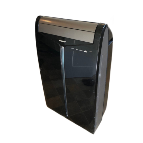
PART NAMES FRONT VIEW REAR VIEW NOTE: Actual unit might vary slightly from above illustration. 1 Air Outlet 2 Vertical louvers 3 Horizontal louvers 4 Remote control signal receiver window 5 POWER Button 6 OPERATION Lamp (red) 7 TIMER Lamp (orange) 8 MEGA COOL Lamp (green) 9 Air inlet 0 Exhaust air outlet... -
Page 11: Remote Control
REMOTE CONTROL REMOTE CONTROL DISPLAY 1 Transmitter 2 Display 3 POWER Button 4 TEMPERATURE Button 5 SLEEP Button 6 MODE Button 7 ON TIMER Button 8 FAN Button 9 OFF TIMER Button 0 CANCEL Button q LOUVERS Button w RESET Button e MEGA COOL Button Light absorbing material is used for the POWER button. -
Page 12: Install Window Panel
INSTALL WINDOW PANEL Installation in a double-hung sash window (See page 12 for installation in a sliding sash window. ) Connect the rain guards to the insect guard net. Insert all three projections on each rain guard into the holes in the insect guard net. Side “A”... - Page 13 If the inner width of the window is between 24" (609mm) and 36.8" (934mm) inclusive. (1) Open the window sash and place the window panel on the window stool. (2) Slide the adjustment panel to fi t the window frame width. (3) Secure the window panel to the stool with 3 screws.
-
Page 14: Installation In A Sliding Sash Window
INSTALL WINDOW PANEL Installation in a sliding sash window (See page 10 for installation in a double-hung window.) Connect the rain guards to the insect guard net. Insert all three projections on each rain guard into the holes in the insect guard net. - Page 15 If the inner height of the window is b e t w e e n 2 4 " ( 6 0 9 m m ) a n d 3 6 . 8 " (934mm) inclusive. (1) Open the window sash and place the window panel on the window frame.
-
Page 16: Installation And Removal Of Exhaust Hose
INSTALLATION AND REMOVAL OF EXHAUST HOSE The exhaust hose must be installed or removed in accordance with the usage mode. MODE COOL, FAN, VENTILATION, DEHUMIDIFICATION with no container DEHUMIDIFICATION with container (minimum capacity 3 Installation of the exhaust hose Attach the window exhaust adapter to the exhaust hose. - Page 17 Removal of the exhaust hose Remove the window exhaust adapter. Pull out and remove the window exhaust adapter by pushing down two markings, and slide and close the exhaust cover in the window panel. Remove the exhaust hose adapter from the unit.
-
Page 18: Pre-Operation Checks
The circuit breaker is activated, power is supplied, and the air conditioner is now ready for use. Do not attempt to use the air conditioner if the above procedure cannot be performed. Disconnect the power plug and call for service. -
Page 19: How To Use The Remote Control
HOW TO USE THE REMOTE CONTROL Point the remote control towards the units signal receiver window and press the desired button. beep will sound when the unit re- ceives the signal. • Make sure nothing, such as curtains, blocks the signal receiver window. •... -
Page 20: Cool Mode
COOL MODE Drainage nozzle "CLOSE" position Stopcock Stopcock Drainpipe nozzle Install the exhaust hose (See Page14), turn the drainage nozzle to the CLOSE position, and check the drainage nozzle is covered with the stopcock. Ensure that the stopcock is securely inserted into the lower drainpipe nozzle and that the nozzle has not been damaged. -
Page 21: Dehumidification Mode
DEHUMIDIFICATION MODE In this mode, the air conditioner dehumidifi es the room. Ensure that the stopcock is securely inserted into the lower drainpipe nozzle and that the nozzle has not been damaged. Dehumidifi cation with container Remove the exhaust hose (See Page 15) Turn the drainage nozzle to the OPEN position. -
Page 22: Fan Mode
FAN MODE In this mode, the air conditioner simply circulates the air without cooling it. Install the exhaust hose (See Page14), turn the drainage nozzle to the CLOSE position, and check the drainage nozzle is covered with the stopcock. Ensure that the stopcock is securely inserted into the lower drainpipe nozzle and that the nozzle has not been damaged. -
Page 23: To Change Air Flow Direction
TO CHANGE AIR FLOW DIRECTION UP / DOWN AIR FLOW DIRECTION LEFT / RIGHT AIR FLOW DIRECTION CAUTION Never attempt to adjust the horizontal louvers manually. • Manual adjustment of the horizontal louvers can cause the unit to malfunction when the remote control is used for adjustment. -
Page 24: Mega Cool Operation
MEGA COOL OPERATION In this operation, the air conditioner fan works at extra high speed with a setting temperature of 59°F. NOTES: • You cannot set the temperature or fan speed during MEGA COOL operation. • The fan returns to the HIGH speed setting after the unit has run for 30 minutes in MEGA COOL mode. -
Page 25: Timer Operation
TIMER OPERATION ON TIMER The unit will turn on automatically according to your setting. Timer duration can be set from a minimum of half an hour (30 minutes) to a maxi- mum of 12 hours. Up to 9.5 hours, you can set in half-hour (30-minute) increments and from 10 to 12 hours, in 1-hour increments. -
Page 26: Off Timer
TIMER OPERATION OFF TIMER The unit will turn off automatically according to your setting. Timer duration can be set from a minimum of half an hour (30 minutes) to a maxi- mum of 12 hours. Up to 9.5 hours, you can set in half-hour (30-minutes) increments and from 10 to 12 hours, in 1-hour increments. -
Page 27: Main Unit Operation
MAIN UNIT OPERATION Use this mode when the remote control is not available. NOTES: • Upon starting MAIN UNIT operation, the drainage pump inside the unit runs for about a minute, which may produce an audible gurgling sound. Press the POWER button on the unit. •... -
Page 28: Drainage
DRAINAGE Prepare for drainage and drain out water within the unit in the following cases. If the unit stops operating and the TIMER, OPERATION and MEGA COOL lamps are blinking. (This indicates that the water tank inside the unit is full.) Make sure to turn the unit off. -
Page 29: Maintenance
(120°F/50°C or hotter) when cleaning. CLEANING THE INSECT GUARD NET Insect guard net MAINTENANCE AFTER AIR CONDITIONER SEASON Perform drainage to drain out water within the unit. (See Page 26 "When the unit is not used for a long time"). -
Page 30: Before Calling For Service
• Did you restart the unit within 3 minutes of a power failure? If the power was off for less than 3 minutes when, you restarted the air conditioner, a protective device may cause the compressor to shut off, preventing cooling for about 5 minutes. - Page 31 ESPAÑOL Este manual explica cómo utilizar de forma correcta su nuevo acondiciona- dor de aire. Antes de usar el producto lea el manual detenidamente. Este manual debería de guardarse en un lugar seguro para futuras referencias. ÍNDICE • SOLICITU DE SERVICIO AL CLIENTE ... S-2 •...
-
Page 32: Solicitu De Servicio Al Cliente
Ciudad Estado Código postal Teléfono LLAMADAS: Marque el 1-800-BE-SHARP (237-4277) para: SERVICIO (para su centro de servicio autorizado Sharp más cercano) PIEZAS (para su distribuidor autorizado de piezas) ACCESORIOS INFORMACIÓN ADICIONAL PARA LOS CLIENTES CORRESPONDENCIA: Sobre problemas de servicio, información de garantía, ítems... -
Page 33: Garantía Limitada Del Consumidor
La corrección de defectos, en el tiempo y forma aquí descritos, deberán constituir la completa satisfacción de todas las responsabilidades legales de Sharp hacia el comprador con respecto al Producto, y deberán constituir la total satisfacción de todos los reclamos, ya sean basados en un contrato, negligencia, marco legal u otros. -
Page 34: Precauciones
PRECAUCIONES Aspectos a tener en cuenta al utilizar el acondicionador de aire. ADVERTENCIAS PARA EL USO • Instale el acondicionador de aire de acuerdo a las instruc- ciones de instalación que se describen más adelante en este manual. • No modifi que ninguna de las piezas de este producto. •... -
Page 35: Precauciones Para El Uso
ADVERTENCIA ACERCA DE LA CONEXIÓN A TIERRA • El uso inadecuado de la clavija de conexión a tierra puede provacar el riesgo de descargas eléctricas. Este aparato debe de ser conectado a tierra. En caso de que ocurra un cortocircuito, la conexión a tierra reduce el riesgo de una descarga eléctrica, al proporcionar un conducto menos resistente para la corriente eléctrica. -
Page 36: Condiciones De Funcionamiento
PRECAUCIONES OBSERVACIONES SOBRE EL FUNCIONAMIENTO • Deje que pasen 3 minutos para que el compresor reanude el enfriamiento. Si apaga el acondicionador de aire y lo enciende inmediatamente después, deje que pasen tres minutos para que el compresor reanude el enfriamiento. Hay un dispositivo electrónico de la uni- dad que mantiene el compresor desactivado durante tres minutos por seguridad. -
Page 37: Ubicación
UBICACIÓN • El acondicionador de aire debería de colocarse en un lugar fi rme para minimizar el ruido y la vibración. Para una colo- cación fi rme y segura, coloque la unidad sobre una superfi - cie lisa, a nivel y lo sufi cientemente fuerte para sostener la unidad. -
Page 38: Designación De Las Piezas
DESIGNACIÓN DE LAS PIEZAS PARTE DELANTERA PARTE TRASERA NOTA: La unidad puede diferir ligeramente de la ilustración de arriba. 1 Orifi cio de salida de aire 2 Defl ectores verticales 3 Defl ectores horizontales 4 Ventana receptora de señal del control remoto 5 Botón POWER 6 Lámpara OPERATION (roja ) -
Page 39: Control Remoto
CONTROL REMOTO PANTALLA DE VISUALIZACIÓN DEL CONTROL REMOTO 1 Transmisor 2 Pantalla de visualización 3 Botón de alimentación (POWER) 4 Botón de temperatura (TEMP) 5 Botón SLEEP 6 Tecla de modo (MODE) 7 Botón de activación del temporizador (ON TIMER) 8 Tecla de ventilación (FAN) 9 Botón de desactivación del temporizador (OFF TIMER) -
Page 40: Instalación Del Panel De Ventana
INSTALACIÓN DEL PANEL DE VENTANA Instalación en una ventana de guillotina doble (Vea la página 12 para la instalación en una ventana de guillotina deslizante). Conecte los protectores contra la lluvia a la red de protección contra insectos. Inserte las tres salientes en cada protector contra la lluvia dentro de los agujeros en la red de protección contra insectos. - Page 41 Si el ancho interior de la ventana está entre 24" (609 mm) y 36,8" (934 mm) inclusive. (1) Abra la hoja de la ventana y coloque el panel de ventana sobre el antepecho. (2) Deslice el panel de ajuste para fi jar el ancho del marco de la ventana.
- Page 42 INSTALACIÓN DEL PANEL DE VENTANA Instalación en una ventana de hoja corredera (Vea la página 10 para obtener información sobre la instalación enuna ventana de guillotina doble). Conecte los protectores contra la lluvia a la red de protección contra insectos. Inserte las tres salientes en cada protector contra la lluvia dentro de los agujeros en la red de protección contra insectos.
- Page 43 Si la altura interior de la ventana esta entre 24" (609 mm) y 36,8" (934 mm) inclusive. (1) Abra la hoja de la ventana y coloque el panel de ventana sobre el marco. (2) Deslice el panel de ajuste para fi jar la altura del marco de la ventana.
-
Page 44: Instalación Y Desmontaje De La Manguera De Escape
INSTALACIÓN Y DESMONTAJE DE LA MANGUERA DE ESCAPE La manguera de escape debe de instalarse o desmontarse de acuerdo con el modo de uso. MODO ENFRIAR, VENTILADOR, VENTILACIÓN, DESHUMIDIFICACIÓN sin depósito Instalar DESHUMIDIFICACIÓN sin depósito (capacidad mínima 3 Instalación de la manguera de escape Fije el adaptador del escape de la ventana a la manguera de escape. - Page 45 Desmontaje de la manguera de escape Desmonte el adaptador del escape de la ventana. Al presionar las dos marcas “PUSH”, tire y extraiga el adaptador del escape de la ventana, deslice y cierre la cubierta del escape en el panel de ventana. Desmonte el adaptador de la manguera de escape de la unidad.
-
Page 46: Revisiones Antes De Iniciar El Funcionamiento
REVISIONES ANTES DE INICIAR EL FUNCIONAMIENTO REVISIÓN DE LA CLAVIJA DE TOMA DE CORRIENTE Este acondicionador de aire utiliza una clavija de toma de corriente con fusible. Antes de iniciar el funcionamiento verifi que siempre la clavija de toma de corriente. Presione el botón de reinicio (RESET). - Page 47 FORMA DE USAR EL CONTROL REMOTO Apunte el control remoto hacia la ventana receptora de señal de la unidad y presione el botón des- eado. Cuando la unidad reciba la señal, producirá un sonido audible. • Asegúrese de que nada, como por ejemplo cortinas, bloquea la ven- tana receptora de señal.
-
Page 48: Modo Enfriar
MODO ENFRIAR Boquilla de drenaje Posición “CERRAR” Llave de paso Llave de paso Boquilla del tubo de drenaje Instale la manguera de escape (vea la página 14), gire la boquilla de drenaje a la posición CERRAR y compruebe que la boquilla de drenaje está... -
Page 49: Modo Deshumidificación
MODO DESHUMIDIFICACIÓN En este modo, el acondicionador de aire deshumidifi ca la habitación. Asegurar que la llave de paso este insertada en la parte baja de el tubo de desagueh de boquilla y que la boquilla no este dañada. Deshumidifi cación con depósito Desmonte la manguera de escape (vea la página 15) Gire la boquilla de drenaje a la posición ABRIR. -
Page 50: Modo Ventilador
MODO VENTILADOR En este modo, el acondicionador de aire simplemente hace que el aire circule sin hacer que se enfríe. Instale la manguera de escape (vea la página 14), gire la boquilla de drenaje a la posición CERRAR y compruebe que la boquilla de drenaje está cubierta con la llave de paso. Asegurar que la llave de paso este insertada en la parte baja de el tubo de desagueh de boquilla y que la bo- quilla no este dañada. -
Page 51: Cambio De La Dirección De La Corriente De Aire
CAMBIO DE LA DIRECCIÓN DE LA CORRIENTE DE AIRE DIRECCIÓN DE LA CORRIENTE DE AIRE HACIA ARRIBA/ABAJO DIRECCIÓN DE LA CORRIENTE DE AIRE HACIA LA IZQUIERDA/DERECHA PRECAUCIÓN No trate nunca de graduar manualmente los defl ectores horizontales. • Si se ajustan los defl ectores horizontales de forma manual, puede suceder que la unidad falle posteriormente al querer manejarla con el control remoto. -
Page 52: Funcionamiento Mega Cool
FUNCIONAMIENTO MEGA COOL En esta función, el ventilador del acondicionador de aire funciona a una velocidad muy alta con una temperatura ajustada a 59°F. NOTAS: • No es posible ajustar la temperatura o la velocidad del ventilador durante el funcionamiento en MEGA COOL. -
Page 53: Funcionamiento Con El Temporizador
FUNCIONAMIENTO CON EL TEMPORIZADOR ACTIVACIÓN DEL TEMPORIZADOR La unidad se activará automáticamente según sus ajustes. La duración del temporizador se puede ajustar a partir de un mínimo de media hora (30 minutos) a un máximo de 12 horas. Puede ajustar en incrementos de media hora (30 minutos) hasta 9,5 horas y desde 10 a 12 horas, en incrementos de 1 hora. - Page 54 FUNCIONAMIENTO CON EL TEMPORIZADOR DESACTIVACIÓN DEL TEMPORIZADOR La unidad se desactivará automáticamente según sus ajustes. La duración del temporizador se puede ajustar a partir de un mínimo de media hora (30 minutos) a un máximo de 12 horas. Puede ajustar en incrementos de media hora (30 minutos) hasta 9,5 horas y desde 10 a 12 horas, en incrementos de 1 hora.
-
Page 55: Funcionamiento De La Unidad Principal
FUNCIONAMIENTO DE LA UNIDAD PRINCIPAL Use este modo si no dispone de un control remoto. NOTAS: • En el inicio del funcionamiento de la UNIDAD PRINCIPAL, la bomba de drenaje en el interior de la unidad funciona durante un minuto aproximadamente, lo cual puede producir un sonido de gorgoteo. -
Page 56: Drenaje
DRENAJE Prepare todo lo necesario para el drenaje y drene el agua que se encuentra dentro de la unidad en los siguientes casos. Si la unidad deja de funcionar y las lámparas TIMER, OPERATION y MEGA COOL par - padean. (Esto indica que el depósito del agua dentro de la unidad está lleno). Asegúrese de desactivar la unidad. -
Page 57: Mantenimiento
MANTENIMIENTO Asegúrese de desconectar la energía del enchufe de pared antes de realizar cualquier mantenimiento. LIMPIEZA DE LOS FILTROS Si el fi ltro está obstruido con polvo, se reducirá la corriente de aire, dando como resultado una baja capacidad de enfriamiento. El fi ltro debería de limpiarse cada dos semanas. LIMPIEZA DE LA UNIDAD Y DEL CONTROL REMOTO Límpielos con un paño suave y seco o con un paño húmedo con jabón neutro. -
Page 58: Antes De Llamar Al Departamento De Servicio Técnico
ANTES DE LLAMAR AL DEPARTAMENTO DE SERVICIO TÉCNICO Si la unidad parece estar funcionando mal, verifi que los siguientes puntos antes de llamar al servicio técnico. EL ACONDICIONADOR DE AIRE NO FUNCIONA • ¿Está la unidad enchufada o está la clavija holgada? •... - Page 60 SHARP ELECTRONICS CORPORATION Sharp Plaza, Mahwah, New Jersey 07430-2135 U.S.A SHARP CORPORATION Printed in Thailand S-31 TINSEA553JBRZ 08A-...