Table of Contents
Advertisement
Advertisement
Table of Contents

Related Manuals for Keys Fitness HealthTrainer 502t


Summary of Contents for Keys Fitness HealthTrainer 502t
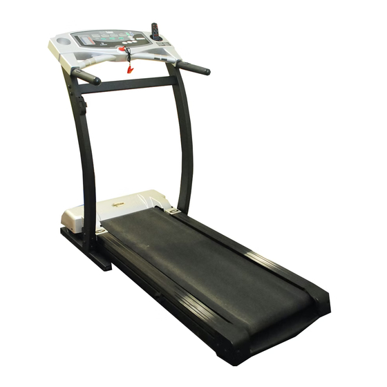
- Page 1 Owner’s Manual HEALTH TRAINER 502t TREADMILL Customer Service (888) 340-0482 Keys Fitness Products 4009 Distribution Drive Suite 250 Garland, TX 75041 www.keysfitness.com Model Name : 502t Serial Number : Purchase Date : Write down for future reference Serial Number Decal Location...
-
Page 2: Table Of Contents
Table of Contents Important Safety Information Before You Start Assembly Warm Up Exercises Moving Instructions Power Requirements Console Panel Functions Program and Operation Program Profiles Belt Adjustment Change to MPH or KPH Maintenance Instructions Troubleshooting Guide Error Messages Calibration Sequence Parts List Exploded View Warranty Information... -
Page 3: Important Safety Information
2. This treadmill has a user maximum capacity of 250 pounds. 3. The treadmill should only be used on a level surface and is intended for indoor use only. The treadmill should not be placed in a garage, patio, or near water and should never be used while you are wet. Keys rec- ommends a treadmill mat be placed under the treadmill to protect floor or carpet and for easier cleaning. -
Page 4: Before You Start
Before You Start Thank you for purchasing the HEALTH TRAINER 502t Treadmill! This quality product you have chosen was designed to meet your needs for cardiovascular exercise. Before you start, please read the Owner's Manual and become familiar with the operation of your new treadmill. -
Page 5: Assembly
Assembly The HEALTH TRAINER 502t treadmill will require assembly before operating. After opening the box, remove any packing material from the treadmill. Do not throw away any packing materials until the unit is working properly. Place the base on a clean, level surface. Make sure the electrical cord will easily reach an electrical outlet. - Page 6 Assembly requires the included allen wrench and your own phillips screwdriver. Do not plug in the power cord until all assembly step are completed. 1. With the treadmill deck in the down position, leave the unit on the original packing material to assemble all parts.Refer to figure 1.
- Page 7 Assembly 3. Install Left Upright and Right Upright to tread- mill base frame. Refer to Figure 4. Note: Make sure that the Wire Harness is not pinched. Do not install hardware until instructed. 4. Install the Upright Crossbar Assembly to Left and Right Upright as shown in Figure 5.
- Page 8 Assembly 8. Connect the Console Harness and Remote Speed Harness together as shown in Figure 7. Connectors snap together as shown in Figure 8. CONSOLE HARNESS 9. Connect Ground Wire to grounding screw located on the side of the Upright Assembly using Screw ST4.2*13 (Qty.
- Page 9 Assembly 10. Make sure all wires and harnesses are inside console housing and attach the console back cover to the Left and Right Upright mounting brackets using Screws ST4.2*16 (Qty. 6) as shown in Figure 9. SCREW ST4.2*16 Figure 9: Console Back Cover Installation 11.
-
Page 10: Warm Up Exercises
Warm Up Exercises EXERCISE GUIDELINES WARNING! Before beginning this or any exercise program, you should consult your physician. This is espe- cially important for individuals over the age of 35 or individuals with pre-existing health problems. Warming up prepares the body for the exercise by increasing circulation, supplying more oxygen to the mus- cles and raising body temperature. -
Page 11: Moving Instructions
Using extreme caution, move the treadmill to the desired location. To set the treadmill down, place one foot on the center of the base crossbar and carefully lower treadmill onto base in resting position. -
Page 12: Power Requirements
This treadmill can be seriously damaged by sudden voltage changes in your home’s electrical power. Voltage spikes, surges, and noise interference can result from weather conditions or from other appliances being turned on or off. To reduce the possibility of treadmill damage, always use a surge protector (not included) with your treadmill. -
Page 13: Console Panel Functions
Console Panel Functions There are four display windows on the control panel to provide feedback information. TIME WINDOW TIME: Indicates elapsed time after pressing start in minutes and seconds (0-99 minutes, 0-59 seconds) INTERVAL TIME: Indicates countdown in seconds to the next interval starting at 5 seconds and counting to 0 seconds SPEED WINDOW SPEED: Indicates MPH (miles per hour) or KPH (kilometer per hour) in .1 increments... -
Page 14: Program And Operation
Program and Operation QUICK START / MANUAL MODE 1. Plug into a surge protector outlet. Attach the Red Safety Key on to the treadmill console. 2. Stand on the treadmill and straddle belt. Attach safety key clip to your clothes. - Page 15 2. Press POWER button. There will be an eight (8) second delay before data can be entered. The TIME win- dow will flash. 3. There are three (3) pre-set and six (6) custom pre-set programs on the HT502t. The treadmill includes FAT BURN, CARDIO, and WARM-UP programs. To Select the program press the MODE button until desired program is illuminated on console display.
-
Page 16: Program Profiles
1 2 3 4 5 6 7 8 9 1 0 The Warm Up Program is designed to gradually increase the treadmill Speed and Elevation in the first segment (warm up) and gradually decrease the treadmill Speed and Elevation in the last segment (cool down). -
Page 17: Belt Adjustment
“Walking Belt Slipping” instructions. WALKING BELT IS SHIFTING TO THE RIGHT (Diagram 2) First, turn the treadmill on to run at 1 mph. Using the hex key pro- vided, turn the right rear roller adjustment bolt ¼ turn in the clock- wise direction. -
Page 18: Change To Mph Or Kph
1) Turn power OFF on the console. (Do not unplug treadmill) Attach the magnet safety key to the console. 2) Activate the calibration mode switch by inserting the eraser end of a pencil into the opening in the backside of the console (see diagram below). -
Page 19: Maintenance Instructions
Keys Fitness recommends “Lube N Walk” for cleaning and lubricating the treadmill belt and deck. Ask your retailer or call Keys Fitness at 888-340-0482. You may also use silicone such as “Napa 8300” (available at most NAPA Auto Parts stores). -
Page 20: Troubleshooting Guide
(Refer to “Power Requirements” on page 12). 3. Check the circuit breaker located on the front of the treadmill. If the switch protrudes, it has tripped. Wait five minutes and then press the switch back in. -
Page 21: Error Messages
Error Messages Treadmill Error Messages. Your treadmill is equipped with a software package that enables error messages to be displayed when there is a problem. The following error codes will be displayed in the console display windows. Safety Interlock Error Messages SI 1 - Safety key missing, replace and try again. -
Page 22: Calibration Sequence
Calibration Sequence Do not attempt to calibrate the treadmill unless an Error Code is present. See Error Messages (page 21). Our treadmill is equipped with a software package that will perform a calibration sequence unique to your specific model number. -
Page 23: Parts List
411-00002 408-00002 402-00003 402-00004 402-00005 402-00006 402-00007 402-00008 402-00009 402-00010 402-00011 HEALTHTRAINER 502t PARTS LIST DESCRIPTION UPRIGHT CROSSBAR LEFT UPRIGHT RIGHT UPRIGHT BASE TUBE DECK FRAME MOTOR FRAME WALK BELT 430*2700*1.6 WALK BOARD 1162*610*18 POLY V-BELT 200J8(508J8) MOTOR COVER 720*350*115 END CAP 616*130*2.5... - Page 24 402-00041 407-00002 413-00001 406-00018 413-00002 414-00001 407-00003 408-00003 413-00003 402-00042 HEALTHTRAINER 502t PARTS LIST DESCRIPTION ALLEN BOLT M8*40 ALLEN BOLT M8*40 SCREW M6*25 PHILIP SCREW ST4.2*16 PHILIP SCREW ST4.2*13 PHILIP SCREW M4*8 PHILIP SCREW M6*12 PHILIP SCREW ST4.2*13 HEXAGRAM NUT M3...
-
Page 25: Parts List
413-00010 413-00011 408-00009 426-00001 415-00001 415-00002 414-00003 414-00004 414-00005 414-00006 414-00007 414-00008 414-00009 HEALTHTRAINER 502t PARTS LIST DESCRIPTION SAFETY KEY DECAL MOTOR CONTROLLER 110V MOTOR 110V 1.5 MOTOR FLYWHEEL SCREW SCREW WASHER ACTUATOR 110V 1/15 POWER CORD CIRCUIT BREAKER POWER RECEPTACLE... -
Page 26: Exploded View
Exploded View... -
Page 27: Exploded View
Exploded View CONSOLE ASSEMBLY... -
Page 28: Warranty Information
Keys. Keys reserves the right to change manufacturers of any part to cover any existing warranty. To obtain warranty service, you must contact a Keys authorized service technician or Keys Fitness at our phone numbers located in this manual. Any parts deter- mined to be defective must be returned to Keys to obtain warranty service. - Page 29 Customer Service (888) 340-0482 Keys Fitness Products 4009 Distribution Drive Suite 250 Garland, TX 75041 www.keysfitness.com...