Table of Contents
Advertisement
Quick Links
Service Literature
80UHG series units are mid−efficiency gas furnaces used
for upflow or horizontal applications only, manufactured
with tubular heat exchangers formed of aluminized steel.
80UHG units are available in heating capacities of 45,000
to 120,000 Btuh and cooling applications up to 5 tons. Refer
to Engineering Handbook for proper sizing.
Units are factory equipped for use with natural gas. Kits are
available for conversion to LPG operation. 80UHG−1 model
units use electronic (direct spark) ignition. 80UHG−2 and −3
model units are equipped with the Lennox SureLight silicon
nitride ignition system. The 80UHGX unit meets the Califor
nia Nitrogen Oxides (NO
x
sonal Efficiency requirements. All units use a redundant gas
valve to assure safety shut−off as required by A.G.A. or
C.G.A. Units may be installed in upflow or horizontal posi
tion.
All specifications in this manual are subject to change. Pro
cedures outlined in this manual are presented as a recom
mendation only and do not supersede or replace local or
state codes. In the absence of local or state codes, the
guidelines and procedures outlined in this manual (except
where noted) are recommended only and do not constitute
code.
TABLE OF CONTENTS
Introduction
. . . . . . . . . . . . . . . . . . . . . . . . . . . . . . . . . . . .
. . . . . . . . . . . . . . . . . . . . . . . . . . . . . . . . . .
. . . . . . . . . . . . . . . . . . . . . . . . . . . . . . . . .
High Altitude
. . . . . . . . . . . . . . . . . . . . . . . . . . . . . . . . . . .
. . . . . . . . . . . . . . . . . . . . . . . . . . . .
I Unit Components
. . . . . . . . . . . . . . . . . . . . . . . . . . .
II Installation
. . . . . . . . . . . . . . . . . . . . . . . . . . . . . . . . . .
III Start Up
. . . . . . . . . . . . . . . . . . . . . . . . . . . . . . . . . . . .
IV Heating System Service Checks
V Typical Operating Characteristics
VI Maintenance
. . . . . . . . . . . . . . . . . . . . . . . . . . . .
VII Wiring and Sequence of Operation
VIII SureLight Troubleshooting Guide
) Standards and California Sea
6−15
. . . . . . . . . . .
16−17
. . . . . . . . . . . . . .
19−20
. . . . . . . . .
21−28
. . . . . . . . . .
29−34
Corp. 9728−L12
Revised 01−2002
1
2
3−4
4
5−6
15
15
18
Page 1
80UHG
1999 Lennox Industries Inc.
Litho U.S.A.
Advertisement
Table of Contents
Troubleshooting

Related Manuals for Lennox 80UHG2-45


Summary of Contents for Lennox 80UHG2-45
- Page 1 Units are factory equipped for use with natural gas. Kits are available for conversion to LPG operation. 80UHG−1 model units use electronic (direct spark) ignition. 80UHG−2 and −3 model units are equipped with the Lennox SureLight silicon nitride ignition system. The 80UHGX unit meets the Califor nia Nitrogen Oxides (NO ) Standards and California Sea sonal Efficiency requirements.
- Page 2 Page 2...
- Page 3 Page 3...
- Page 4 NOTE-In Canada, certification for installations over 4500 ft. (1372m) above sea level is the jurisdictionof the local authorities. Page 4...
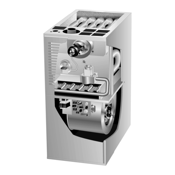
- Page 5 VENT ADAPTER CABINET TOP HEAT EXCHANGER ASSEMBLY FLUE BOX COMBUSTION AIR PROVE INDUCER SWITCH 80UHG CABINET FRONT ACCESS PANEL BURNER ASSEMBLY TRANSFORMER CONTROL BOARD SECONDARY LIMITS CABINET BOTTOM BLOWER ASSEMBLY DOOR INTERLOCK SWITCH FIGURE 1 FIGURE 2...
- Page 6 VEST PANEL FIGURE 3 DANGER CAUTION Electrostatic discharge can affect electronic components. Take precautions during furnace installation and service to protect the furnace's electronic controls. Precautions will help to avoid control exposure to electrostatic dis charge by putting the furnace, the control and the technician at the same electrostatic poten tial.
- Page 7 3− Furnace Control (A3) a−Electronic Ignition (See Figure 5) On a call for heat the SureLight control monitors the com 80UHG−2, −3 Models bustion air inducer pressure switch. The control will not be 80UHG−2 and −3 model units are equipped with the Len gin the heating cycle if the prove switch is closed (by−...
- Page 8 The SureLight board is equipped with two LED lights for troubleshooting. The diagnostic codes are listed below in table 3. TABLE 3 DIAGNOSTIC CODES MAKE SURE TO ID LED’S CORRECTLY: REFER TO INSTALLATION INSTRUCTIONS FOR CONTROL BOARD LAYOUT. LED #1 LED #2 DESCRIPTION Power −...
- Page 9 SURELIGHT INTEGRATED CONTROL BOARD TERMINAL DESIGNATIONS SURELIGHT IGNITOR FIGURE 6 FIGURE 7 NORMAL FLAME SIGNAL u MICROAMPS LOW FLAME SIGNAL v 0.2 MICROAMPS MINIMUM FLAME SIGNAL v 0.15 MICROAMPS NOTE - The 80UHG furnace contains electronic components that are polarity sensitive. Make sure that the furnace is wired correctly and is properly grounded.
- Page 10 DANGER NOTE If fan off" time is set too low, residual heat in *NOTE-If flame is established beyond the 10 second flame heat exchanger may cause primary limit S10 to trip, re stabilization period then lost, the control resets for five more sulting in frequent cycling of blower.
- Page 11 EGC 2 DIAGNOSTIC CODES DIAG #2 DIAG #1 DIagnostic Condition FIGURE 10...
- Page 12 BLOWER CONTROL A15 TERMINAL DESIGNATIONS Terminal Designation Type Function (See fig. 10) FIGURE 11 EGC 2 CONTROL JACK/PLUG 20 TERMINAL DESIGNATIONS Pin # Function...
- Page 13 INSULATING COVER (s)
- Page 15 B-Heating Start Up PROVE SWITCH WARNING White Rodgers 36E Gas Valve -- Honeywell VR8205 Gas Valve -- White Rodgers 36E Gas Valve -- Honeywell VR8205 Gas Valve -- NOTE–When unit is initially started, steps 1 through 11 may need to be repeated to purge air from pilot line. Turning Off Gas To Unit C-Safety or Emergency Shutdown D-Extended Period Shutdown...
- Page 16 B-Gas Piping C-Testing Gas Piping IMPORTANT IMPORTANT TABLE 9 GAS VALVE REGULATION Natural FIGURE 20 L.P.
- Page 17 NOTE-Shut unit off and remove manometer as soon as an accurate reading has been obtained. Take care to replace pressure tap plug. Divide by two NOTE- To obtain accurate reading, shut off all other gas appliances connected to meter. IMPORTANT...
- Page 18 WARNING NOTE- The following is a generalized procedure and does not apply to all thermostat controls. °...
- Page 19 BLOWER SPEED TAP SELECTION Leaded Motors NOTE-Use papers or protective covering in front of fur nace while cleaning furnace. FIGURE 24...
- Page 20 HEAT EXCHANGER REMOVAL (unit shown in horizontal position) FIGURE 25 CAUTION...
- Page 22 ABNORMAL HEATING MODE NORMAL HEATING MODE...
- Page 26 HEATING SEQUENCE CONTINUED NORMAL HEATING MODE ABNORMAL HEATING MODE 15 SECOND COMBUSTION AIR INDUCER PREPURGE INITIATED BY CLOSED PRESSURE SWITCH. IS VOLTAGE ABOVE 75 VOLTS? LEDS SIGNAL IGNITOR WARM UP −− 20 SECONDS. ALTERNATING IS THERE A PROPER GROUND? FAST FLASH 4 SECOND TRIAL FOR IGNITION.
- Page 29 VIII-Troubleshooting-SureLight Control...