Lennox ML196UHE Installation Instructions Manual
Hide thumbs
Also See for ML196UHE:
- Unit information (56 pages) ,
- User's information manual (7 pages) ,
- Unit information (57 pages)
Table of Contents
Advertisement
© 2021 Lennox Industries Inc.
Dallas, Texas USA
Contents
Unit Dimensions - inches (mm) ......................................2
ML196UHE .....................................................................3
Shipping and Packing List ..............................................3
Safety .............................................................................3
Use of Furnace as a Construction Heaterl .....................4
General ...........................................................................5
Combustion, Dilution, Ventilation Air...............................5
Setting Equipment ..........................................................8
Filters ............................................................................13
Duct System .................................................................13
Pipe Fittings Specifications...........................................13
Joint Cementing Procedure ..........................................16
Venting Practices ..........................................................16
INSTALLATION
INSTRUCTIONS
ML196UHE
MERIT
SERIES GAS FURNACE
®
UPFLOW / HORIZONTAL AIR DISCHARGE
507966-04
04/2021
Supersedes 507966-03
THIS MANUAL MUST BE LEFT WITH THE
HOMEOWNER FOR FUTURE REFERENCE
This is a safety alert symbol and should never be
ignored. When you see this symbol on labels or in man-
uals, be alert to the potential for personal injury or death.
Improper installation, adjustment, alteration, service
or maintenance can cause property damage, personal
injury or loss of life. Installation and service must be
performed by a licensed professional HVAC installer (or
equivalent), service agency or the gas supplier.
As with any mechanical equipment, contact with sharp
sheet metal edges can result in personal injury. Take
care while handling this equipment and wear gloves and
protective clothing.
Gas Piping ....................................................................36
Electrical .......................................................................39
Unit Start-Up .................................................................42
Gas Pressure Measurement.........................................44
Proper Combustion.......................................................44
High Altitude .................................................................44
Testing Combustion Air For Non-Dierct Vent ................46
Other Unit Adjustments.................................................46
Service..........................................................................48
Repair Parts List ...........................................................49
Start-Up Checklist.........................................................51
Blower Data ..................................................................53
Page 1
WARNING
CAUTION
Advertisement
Table of Contents

Related Manuals for Lennox ML196UHE


Summary of Contents for Lennox ML196UHE
-
Page 1: Table Of Contents
INSTALLATION INSTRUCTIONS ML196UHE © 2021 Lennox Industries Inc. Dallas, Texas USA MERIT SERIES GAS FURNACE ® UPFLOW / HORIZONTAL AIR DISCHARGE 507966-04 04/2021 Supersedes 507966-03 THIS MANUAL MUST BE LEFT WITH THE HOMEOWNER FOR FUTURE REFERENCE This is a safety alert symbol and should never be ignored. -
Page 2: Unit Dimensions - Inches (Mm)
Unit Dimensions - inches (mm) NOTE - 60C size units that require air volumes over 1800 cfm must have one of the following: EXHAUST AIR 1. Single side return air and Optional Return Air Base 3-3/8 OUTLET with transition that must accommodate required (86) 20 x 25 x 1 inch (508 x 635 x 25 mm) air filter to maintain proper velocity. -
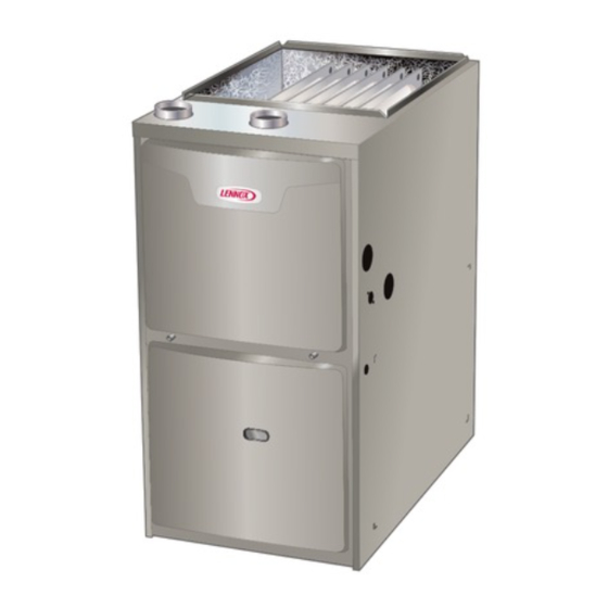
Page 3: Ml196Uhe
ML196UHE Gas Furnace Shipping and Packing List Package 1 of 1 contains The ML196UHE Category IV gas furnace is shipped ready for installation in the upflow or horizontal position. The furnace is 1 - Assembled ML196UHE unit shipped with the bottom panel in place. The bottom panel must... -
Page 4: Use Of Furnace As A Construction Heaterl
This ML196UHE furnace must be installed so that its elec- Use of Furnace as Construction Heater trical components are protected from water. -
Page 5: General
These instructions are intended as a general guide and do not supersede local codes in any way. Consult authorities If the ML196UHE is installed as a Non-Direct Vent Fur- having jurisdiction before installation. nace, follow the guidelines in this section. - Page 6 complete and official position of the ANSI on the refer- Even a small leak around the base of the unit at the plat- enced subject, which is represented only by the standard form or at the return air duct connection can cause a po- in its entirety.
- Page 7 EQUIPMENT IN CONFINED SPACE EQUIPMENT IN CONFINED SPACE - ALL AIR FROM OUTSIDE (Inlet Air from Ventilated Crawlspace and Outlet Air to Outside) (Inlet Air from Crawl Space and Outlet Air to Outside) Roof Terminated VENTILATION LOUVERS Exhaust Pipe (Each end of attic) ROOF TERMINATED EXHAUST PIPE OUTLET...
- Page 8 Upflow Applications INLET AIR LOCATION) The ML196UHE gas furnace can be installed as shipped in the upflow position. Refer to Figure 12 for clearances. NOTE-Each air duct opening shall have a free area of at least one Select a location that allows for the required clearances square inch per 2,000 Btu (645mm per .59kW) per hour of the total...
-
Page 9: Setting Equipment
SETTING EQUIPMENT UPFLOW APPLICATION Place level on blower Place level on the front blower deck screws to check deck to check side to side forward tilt UNIT FRONT AIR FLOW 1/2” max. SIDE VIEW HORIZONTAL APPLICATION UNIT FRONT AIR FLOW 1/2”... - Page 10 Refer to Engineering Handbook for additional information. no sagging, cracks, gaps, etc. For no reason should ML196UHE applications which include side return air return and supply air duct systems ever be connected and a condensate trap installed on the same side of...
- Page 11 Optional Return Air Base CONDENSATE (Upflow Applications Only) TRAP FURNACE FRONT 23 (584) 3−1/4 IF BASE Overall (83) IS USED (Maximum) Minimum WITHOUT 11 (279) IAQ CABINET, Maximum 22−7/16 INDOOR AIR A SINGLE Unit side return air 14 (356) (570) QUALITY RETURN AIR Opening...
- Page 12 The ML196UHE furnace can be installed in horizontal ap- NOTE - Heavy-gauge sheet metal straps may be used to plications with either right- or left-hand air discharge. suspend the unit from roof rafters or ceiling joists. When straps are used to suspend the unit in this way, support Refer to Figure 17 for clearances in horizontal applica- must be provided for both the ends.
-
Page 13: Filters
Lennox Product cabinet to ensure a tight seal. If a filter is installed, size the Specifications bulletin. Additional information is provided return air duct to fit the filter frame. - Page 14 D2665 Fittings) IMPORTANT ASTM PRIMER & SOLVENT CEMENT SPECIFICATION ML196UHE exhaust and intake connections are made PVC & CPVC Primer F656 of PVC. Use PVC primer and solvent cement when PVC Solvent Cement D2564 using PVC vent pipe. When using ABS vent pipe, use...
- Page 15 Use PVC primer and solvent cement or ABS solvent ce- inside socket surface of fitting and male end of pipe to ment meeting ASTM specifications, refer to TABLE 2. depth of fitting socket. As an alternate, use all purpose cement, to bond ABS, Canadian Applications Only - Pipe, fittings, primer and PVC, or CPVC pipe when using fittings and pipe made of solvent cement used to vent (exhaust) this appliance must...
-
Page 16: Joint Cementing Procedure
Joint Cementing Procedure Venting Practices All cementing of joints should be done according to the specifications outlined in ASTM D 2855. Piping Suspension Guidelines DANGER SCHEDULE 40 DANGER OF EXPLOSION! PVC - 5' all other pipe* - 3' Fumes from PVC glue may ignite during system check. Allow fumes to dissipate for at least 5 minutes before placing unit into operation.. - Page 17 The ML196UHE can be installed as either a Non-Direct REPLACING FURNACE THAT WAS PART OF A Vent or a Direct Vent gas central furnace. COMMON VENT SYSTEM NOTE - In Non-Direct Vent installations, combustion air CHIMNEY is taken from indoors and flue gases are discharged out- OR GAS doors.
- Page 18 Doing so will cause freeze-ups and may block the terminations. What is the furnace capacity? TABLE 4 MINIMUM VENT PIPE LENGTHS ML196UHE Model MIN. VENT LENGTH* Which style termination 15 ft. or 5 ft. plus 2 elbows 030, 045, -070, -090, 110, 135 being used? or 10 ft.
- Page 19 TABLE 5 Maximum Allowable Intake or Exhaust Vent Length in Feet NOTE - Size intake and exhaust pipe length separately. Values in table are for Intake OR Exhaust, not combined total. Both Intake and Exhaust must be same pipe size. NOTE - Additional vent pipe and elbows used to terminate the vent pipe outside the structure must be included in the total vent length calculation.
- Page 20 TABLE 5 Continued Maximum Allowable Intake or Exhaust Vent Length in Feet NOTE - Size intake and exhaust pipe length separately. Values in table are for Intake OR Exhaust, not combined total. Both Intake and Exhaust must be same pipe size. NOTE - additional vent pipe and elbows used to terminate the vent pipe outside the structure must be included in the total vent length calculation.
- Page 21 TABLE 6 Maximum Allowable Exhaust Vent Lengths With Furnace Installed in a Closet or Basement Using Ventilatd Attic or Crawl Space For Intake Air in Feet NOTE - Additional vent pipe and elbows used to terminate the vent pipe outside the structure must be included in the total vent length calculation.
- Page 22 TYPICAL EXHAUST AND INTAKE PIPE CONNECTIONS IN UPFLOW DIRECT OR NON-DIRECT VENT APPLICATIONS 2” EXHAUST 2” EXHAUST INTAKE INTAKE 2” 2” 2” 2” 3” 3” 030/045/070 Only 1−1/2” TRANSITION Exhaust 2” 6” Min Exhaust DO NOT transition from larger to smaller DO NOT transition pipe in horizontal runs from smaller to larger...
- Page 23 Intake Piping TYPICAL AIR INTAKE PIPE CONNECTIONS The ML196UHE furnace may be installed in either direct UPFLOW NON−DIRECT VENT APPLICATIONS vent or non-direct vent applications. In non-direct vent ap- plications, when intake air will be drawn into the furnace INTAKE...
- Page 24 The ML196UHE is then classified as a direct vent, of exhausted air as well as the maximum volume of Category IV gas furnace.
- Page 25 TABLE 7 Maximum Allowable Exhaust Vent Pipe Length (in ft.) Without Insulation In Unconditioned Space For Winter Design Temperatures Single - Stage High Efficiency Furnace Winter Vent Unit Input Size Design Pipe Temp °F (°C) Diam 1-1/2 in 32 to 21 2 in (0 to -6) 2-1/2 in...
- Page 26 ‡ Permitted only if veranda, porch, deck or balcony is fully open on a minimum of two sides beneath the floor. Lennox recommends avoiding this location if possible. Figure 32...
- Page 27 ‡ Permitted only if veranda, porch, deck or balcony is fully open on a minimum of two sides beneath the floor. Lennox recommends avoiding this location if possible. Figure 33 Page 27...
- Page 28 8” and TABLE 8 a minimum distance of 6” with a termination elbow. See Figure 42. Exhaust Pipe Termination Size Reduction ML196UHE Model Termination Pipe Size *030, *045, *070 1-1/2” (38mm) *090 2”...
- Page 29 7 - If intake and exhaust piping must be run up a side wall to position above snow accumulation or other obstructions, piping must be supported. At least one FIELD-PROVIDED Accelerator not required REDUCER MAY BE bracket must be used within 6” from the top of the for 3”...
- Page 30 FIELD FABRICATED WALL TERMINATION NOTE − FIELD−PROVIDED REDUCER MAY BE 2” (51mm) 3” (76mm) REQUIRED TO ADAPT LARGER VENT PIPE SIZE Vent Pipe Vent Pipe TO TERMINATION A− Minimum clearance above grade or average 12” (305 mm) 12” (305 mm) snow accumulation B−...
- Page 31 Crawl Space and Extended Horizontal Venting (USA) KIT 15Z70 Lennox provides kit 51W18 (USA) kit 15Z70 (Canada) to (CANADA) install 2” or 3” PVC exhaust piping through the floor joists and into the the crawl space. See Figure 45. This kit can also be used as a supplemental drain for installations with condensate run back in the vent pipe (ie.
- Page 32 Heating cable kit is available from Lennox in various lengths; 6 ft. (1.8m) - kit no. 26K68 and 24 ft. (7.3m) - kit no. 26K69. Page 32...
- Page 33 Condensate Trap With Optional Overflow Switch CONDENSATE TRAP LOCATIONS (Unit shown in upflow position with remote trap) From Evaporator Coil HorizontalFurnace4” Min. to 5” Max.above condensatedrain connection) FieldProvidedVent Min. 1” Above Condensate Drain Connection 1” Min. 2” Max. FurnaceCondensate DrainConnection *5’...
- Page 34 Furnace with Evaporator Coil Using a Separate Drain (Unit shown in horizontal left-hand discharge position) Field Provided Vent Evaporator (4” min. to 5” max. above Coil condensate connection) 4”min 5”max 5’ max. PVC Pipe Only Condensate Drain Connection (Trap at coil is optional) Drain Pan Piping from furnace and evaporator coil must slope down a minimum 1/4”...
- Page 35 TRAP / DRAIN ASSEMBLY USING 1/2” PVC OR 3/4” PVC Optional Condensate Drain Connection Adapter 3/4 inch slip X 3/4 inch mpt (not furnished) 90° Street Elbow 3/4 inch PVC (not furnished) Adapter 3/4 inch slip X 3/4 inch mpt (not furnished) Condensate Drain Connection In Unit 1 (25 mm) Min.
-
Page 36: Gas Piping
6 - In some localities, codes may require installation of a Gas Piping manual main shut-off valve and union (furnished by Gas supply piping should not allow more than 0.5”W.C. installer) external to the unit. Union must be of the drop in pressure between gas meter and unit. - Page 37 Upflow Application Upflow Application Left Side Piping Right Side Piping (Standard) (Alternate) 1/2” NPT 1/2” NPT MANUAL MAIN SHUT-OFF VALVE MANUAL MAIN SHUT-OFF VALVE GROUND GROUND JOINT JOINT UNION UNION DRIP LEG FIELD PROVIDED AND INSTALLED DRIP LEG NOTE - BLACK IRON PIPE ONLY TO BE ROUTED INSIDE OF CABINET Figure 56 Horizontal Applications Possible Gas Piping Configurations...
- Page 38 TABLE 9 Gas Pipe Capacity - ft3/hr (m3/hr) Nominal Internal Length of Pipe - feet (m) Iron Pipe Diameter Size Inches inches (3.048) (6.096) (9,144) (12,192) (15.240) (18.288) (21.336) (24.384) (27.432) (30,480) (mm) (mm) .622 (12.7) (17.799) (4.87) (3.34) (2.69) (2.29) (2.03) (1.84)
-
Page 39: Electrical
C22.1) for Canada. A green ground wire is provided in the field make-up box. NOTE - The ML196UHE furnace contains electronic com- ponents that are polarity sensitive. Make sure that the fur- nace is wired correctly and is properly grounded. - Page 40 One line voltage “120 HUM” 1/4” spade terminal is pro- 2 - When the ML196UHE is running in the heating vided on the furnace integrated control. See Figure 60 for mode, the indoor blower will run on the heating integrated control configuration. This terminal is energized speed (HEAT).
- Page 41 Figure 59 Page 41...
-
Page 42: Unit Start-Up
Be sure to smell next to the floor because some gas is heavier than air and will settle on the floor. TABLE 11 The gas valve on the ML196UHE is equipped with a gas 1/4” QUICK CONNECT TERMINALS control switch (lever). Use only your hand to move switch. - Page 43 Priming Condensate Trap 9 - Replace the access panel. 10- Turn on all electrical power to to the unit. The condensate trap should be primed with water prior 11- Set the thermostat to desired setting. to start-up to ensure proper condensate drainage. Either pour 10 fl.
-
Page 44: Gas Pressure Measurement
When testing supply gas pressure, use the 1/8” N.P.T. plugged tap or pressure post located on the gas valve TABLE 14 to facilitate test gauge connection. See figure 61. Check ML196UHE Unit CO2% Nat CO2% LP gas line pressure with unit firing at maximum rate. Low pressure may result in erratic operation or underfire. - Page 45 TABLE 15 Manifold and Supply Line Pressure 0-10,000ft. Manifold Pressure in. wg. Supply Line Pressure ML196 in. w.g. Unit 0 - 4500 ft 4501 - 5500 ft 5501 - 6500 ft 6501 - 7500 ft 7501 - 10,000 ft 0 - 10000 ft. Natural 13.0 Models...
-
Page 46: Testing Combustion Air For Non-Dierct Vent
After the ML196UHE gas furnace has been started, the condition of use. following test should be conducted to ensure proper vent-... - Page 47 Annual Furnace Maintenance At the beginning of each heating season, and to comply with the Lennox Limited Warranty, your system should be checked as follows: 1 - Check wiring for loose connections, voltage at Figure 62 indoor unit and amperage of indoor motor.
-
Page 48: Service
10- Inspect the furnace intake and exhaust pipes to make Cleaning the Burner Assembly sure they are in place, structurally sound, without If cleaning the burners becomes necessary, follow the holes, blockage or leakage and the exhaust pipe steps below: is sloped toward the furnace. -
Page 49: Repair Parts List
ADDENDUM FOR ALL THE PROVINCES OF CANADA See below for venting in all the provinces of Canada. Lennox approves the following termination for use in all the provinces of Canada. 12”... - Page 50 Requirements for Commonwealth of Massachusetts Modifications to NFPA-54, Chapter 10 4 - INSPECTION. The state or local gas inspector of the side wall, horizontally vented, gas-fueled equipment Revise NFPA-54 section 10.8.3 to add the following shall not approve the installation unless, upon requirements: inspection, the inspector observes carbon monoxide For all side wall, horizontally vented, gas-fueled equip-...
-
Page 51: Start-Up Checklist
Start-Up & Performance Check List UNIT SET UP (typical) Furnace: Model Number_______________ Serial Number_________________ SUPPLY Line Voltage GAS SUPPLY LP Propane Gas Natural Gas Piping Connections Tight Leak Tested Flter Supply Line Pressure “W.C.________ RETURN AIR Gas Supply Pressure DUCT SYSTEM SUPPLY AIR DUCT Sealed INTAKE / EXHAUST PIPE... - Page 52 UNIT OPERATION HEATING MODE COOLING MODE GAS MANIFOLD PRESSURE “W.C._____ INDOOR BLOWER AMPS______ COMBUSTION SAMPLE CO CO PPM_______ TEMPERATURE DROP ______ Return Duct Temperature _________ INDOOR BLOWER AMPS______ Supply Duct Temperature _______ Temperature Drop = _________ TEMPERATURE RISE TOTAL EXTERNAL STATIC (dry coil) Supply Duct Temperature ________ Supply External Static _______ Return Duct Temperature...
-
Page 53: Blower Data
Blower Data ML196UH030XE36B PERFORMANCE (Less Filter) Air Volume / Watts at Various Blower Speeds External High Medium-High Medium Medium-Low Static (Black) (Brown) (Blue) (Yellow) (Red) Pressure in. w.g. Watts Watts Watts Watts Watts 0.00 1435 1170 1000 0.10 1400 1130 0.20 1360 1085... - Page 54 Blower Data ML196UH070XE48B PERFORMANCE (Less Filter) Air Volume / Watts at Various Blower Speeds External High Medium-High Medium Medium-Low Static (Black) (Brown) (Blue) (Yellow) (Red) Pressure in. w.g. Watts Watts Watts Watts Watts 0.00 1855 1710 1510 1330 1240 0.10 1825 1685 1485...
- Page 55 Blower Data ML196UH090XE60C PERFORMANCE (Less Filter) Air Volume / Watts at Various Blower Speeds External High Medium-High Medium Medium-Low Static (Black) (Brown) (Blue) (Yellow) (Red) Pressure in. w.g. Watts Watts Watts Watts Watts 0.00 2105 1860 1705 1585 1425 0.10 2075 1820 1675...
- Page 56 ML196UH135XE60D PERFORMANCE (Less Filter) Air Volume / Watts at Different Blower Speeds Single Side Return Air − Air volumes in bold (over 1800 Bottom Return Air, Side Return Air with Return Air from cfm) require Optional Return Air Base and field fabricated External Both Sides or Return Air from Bottom and One Side.