Table of Contents
Advertisement
QQ
3 7 63 1515 0
SERVICE MANUAL
10
2003
49784
TE
L 13942296513
1
PRECAUTION. . . . . . . . . . . . . . . . . . . . . . . . . . . . . . . . . . . . . . . . . . . . . . . . . . . . . . . . . . . . . . . . . . . . . . . . . 1-2
2
SPECIFIC SERVICE INSTRUCTIONS . . . . . . . . . . . . . . . . . . . . . . . . . . . . . . . . . . . . . . . . . . . . . . . . . . . . . . 1-4
3
DISASSEMBLY . . . . . . . . . . . . . . . . . . . . . . . . . . . . . . . . . . . . . . . . . . . . . . . . . . . . . . . . . . . . . . . . . . . . . . . 1-5
4
ADJUSTMENT . . . . . . . . . . . . . . . . . . . . . . . . . . . . . . . . . . . . . . . . . . . . . . . . . . . . . . . . . . . . . . . . . . . . . . . 1-23
5
TROUBLESHOOTING . . . . . . . . . . . . . . . . . . . . . . . . . . . . . . . . . . . . . . . . . . . . . . . . . . . . . . . . . . . . . . . . . 1-27
www
.
http://www.xiaoyu163.com
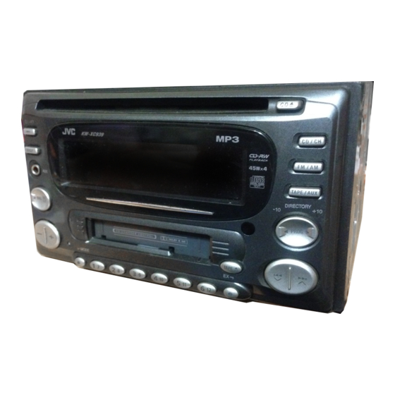
CD/CASSETTE RECEIVER
KW-XC55
TABLE OF CONTENTS
x
ao
u163
y
i
COPYRIGHT © 2003 VICTOR COMPANY OF JAPAN, LIMITED
http://www.xiaoyu163.com
2 9
8
Q Q
3
6 7
1 3
1 5
Area suffix
UN ----------------------------Asean
co
.
9 4
2 8
0 5
8
2 9
9 4
2 8
m
No.49784
9 9
9 9
2003/10
Advertisement
Chapters
Table of Contents

Related Manuals for JVC KW-XC55


Summary of Contents for JVC KW-XC55
-
Page 1: Table Of Contents
3 7 63 1515 0 SERVICE MANUAL CD/CASSETTE RECEIVER 49784 2003 KW-XC55 L 13942296513 Area suffix UN ----------------------------Asean TABLE OF CONTENTS PRECAUTION............... . . 1-2 SPECIFIC SERVICE INSTRUCTIONS . -
Page 2: Precaution
http://www.xiaoyu163.com 3 7 63 1515 0 SECTION 1 PRECAUTION Safety Precautions Burrs formed during molding may be left over on some parts of the chassis. Therefore, pay attention to such burrs in the case of preforming repair of this system. Please use enough caution not to see the beam directly or touch it in case of an adjustment or operation check. - Page 3 http://www.xiaoyu163.com 3 7 63 1515 0 Preventing static electricity Electrostatic discharge (ESD), which occurs when static electricity stored in the body, fabric, etc. is discharged, can destroy the laser diode in the traverse unit (optical pickup). Take care to prevent this when performing repairs. 1.2.1 Grounding to prevent damage by static electricity Static electricity in the work area can destroy the optical pickup (laser diode) in devices such as CD players.
-
Page 4: Specific Service Instructions
http://www.xiaoyu163.com 3 7 63 1515 0 SECTION 2 SPECIFIC SERVICE INSTRUCTIONS This service manual does not describe SPECIFIC SERVICE INSTRUCTIONS. L 13942296513 u163 1-4 (No.49784) http://www.xiaoyu163.com... -
Page 5: Disassembly
http://www.xiaoyu163.com 3 7 63 1515 0 SECTION 3 DISASSEMBLY Main body 3.1.1 Removing the front panel assembly (See Fig.1, 2) (1) From the both side of the main body, remove the four Front panel assembly screws A attaching the front panel assembly. (See Figs.1, Joints a (2) Release the four joints a using a screwdriver, then remove the front panel assembly toward the front. -
Page 6: See Fig.
http://www.xiaoyu163.com 3 7 63 1515 0 3.1.4 Removing the top chassis assembly and bottom chassis assembly (See Fig.5 to 7) • Prior to performing the following procedures, remove the front CN702 panel assembly, rear bracket and heat sink. (1) From the back side of the main body, disconnect the card wire from the connector CN702 on the main board in the... -
Page 7: See Fig.
http://www.xiaoyu163.com 3 7 63 1515 0 3.1.6 Removing the CD mechanism assembly (See Fig.9) • Prior to performing the following procedures, remove the front CD mechanism assembly panel assembly, rear bracket, heat sink, top chassis assembly, main board and CD mecha control board. (1) Remove the three screws J attaching the CD mechanism assembly to the top chassis assembly. - Page 8 http://www.xiaoyu163.com 3 7 63 1515 0 3.1.9 Removing the cassette mechanism assembly (See Fig.13) • Prior to performing the following procedures, remove the front panel assembly, rear bracket, heat sink, bottom chassis assembly, changer control board and mecha control board. (1) From the bottom side of the bottom chassis assembly, remove the four screws M attaching the cassette mechanism assembly to the bottom chassis assembly.
- Page 9 http://www.xiaoyu163.com 3 7 63 1515 0 CD mechanism assembly 3.2.1 Removing the CD mechanism control board 3.2.2 Removing the loading motor (See Fig.1 and 2) (See Fig.3 to 5) (1) Unsolder the part a and b on the CD mechanism control •...
-
Page 10: No.49784)1
http://www.xiaoyu163.com 3 7 63 1515 0 3.2.3 Removing the CD mechanism assembly Damper bracket CD mechanism assembly (See Fig.1, 6 to 9) • Prior to performing the following procedure, remove the CD mechanism control board and the front bracket (loading mo- tor). - Page 11 http://www.xiaoyu163.com 3 7 63 1515 0 3.2.4 Removing the feed motor assembly (See Fig.10) • Prior to performing the following procedure, remove the CD FD screw Part i mechanism control board, the front bracket (loading motor) Feed motor assembly and the CD mechanism assembly. (1) Remove the two screws F and the feed motor assembly.
- Page 12 http://www.xiaoyu163.com 3 7 63 1515 0 Cassette mechanism assembly REFERENCE: Prior to performing the following procedures, turn the mode gear on the bottom of the body until the respective part comes to the EJECT position (Refer to Fig.1). Mode gear Fig.1 3.3.1 Removing the cassette guide (See Fig.2)
-
Page 13: Http://Www.xiaoyu163.Com
http://www.xiaoyu163.com 3 7 63 1515 0 3.3.3 Removing the cassette hanger assembly / cassette holder (See Fig.4 to 7) (1) Check the mode is set to EJECT. Push down the front part Cassette holder assembly of the cassette holder and move in the direction of the ar- row to release the joint c. - Page 14 http://www.xiaoyu163.com 3 7 63 1515 0 3.3.4 Removing the side bracket assembly Side bracket assembly (See Fig.8 to 10) Joint i (1) Remove the screw A attaching the side bracket assembly. (2) Detach the front side of the side bracket assembly upward and pull out forward to release the joint i and j in the rear.
- Page 15 http://www.xiaoyu163.com 3 7 63 1515 0 3.3.5 Removing the pinch arm (F) assembly (See Fig.11 and 12) (1) Remove the polywasher and pull out the pinch arm (F) as- sembly. (2) Remove the compulsion spring. 3.3.6 Removing the pinch arm (R) assembly (See Fig.11 and 12) (1) Remove the polywasher and pull out the pinch arm (R) as- sembly.
- Page 16 http://www.xiaoyu163.com 3 7 63 1515 0 3.3.8 Removing the head / tape guide Flywheel assembly (F) Belt (See Fig.16 and 17) REFERENCE: It is not necessary to remove the slide chassis assembly. (1) Remove the band attaching the wire to the head. (2) Remove the two screws B, the head and the head support spring.
- Page 17 http://www.xiaoyu163.com 3 7 63 1515 0 3.3.10 Disassembling the flywheel assembly (F) FFC pad (See Fig.19 and 20) (1) Push and turn counterclockwise the spring holder (F) to re- lease the three joints p on the bottom of the flywheel. (2) The spring holder (F), the TU spring and the friction gear play come off.
- Page 18 http://www.xiaoyu163.com 3 7 63 1515 0 3.3.13 Removing the gear base arm / gear base link assembly (See Fig.23 to 25) (1) Move the gear base arm in the direction of the arrow. Gear base arm (2) Insert a slotted screwdriver to the gear base spring under Joint t Joints s the gear base arm, and release the gear base arm upward...
- Page 19 http://www.xiaoyu163.com 3 7 63 1515 0 3.3.15 Removing the mode gear Mode gear Mode switch actuator (See Fig.26 and 29) (1) Remove the polywasher on the bottom and pull out the mode gear. 3.3.16 Removing the mode switch actuator (See Fig.26, 27 and 29) (1) Pull out the mode switch actuator at the bottom.
- Page 20 http://www.xiaoyu163.com 3 7 63 1515 0 3.3.19 Removing the gear base assembly / take up gear / reflector gear (See Fig.30 to 32) (1) Push in the pin d’ of the gear base assembly on the upper Slot e' side of the body and move the reflector gear toward the bottom, then pull out.
- Page 21 http://www.xiaoyu163.com 3 7 63 1515 0 3.3.21 Removing the side bracket assembly Side bracket assembly (See Fig.33 to 37) Boss g' (1) Remove the eject cam plate spring. (2) Push the joint f’ through the slot to remove the load rack downward.
- Page 22 http://www.xiaoyu163.com 3 7 63 1515 0 3.3.22 Removing the main motor assembly / sub motor assembly (See Fig.38 to 40) (1) Remove the belt at the bottom. Main motor (2) Remove the polywasher and pull out the mode gear. assembly (3) Pull out the reduction gear (B).
-
Page 23: Adjustment
0dB (1µV,50Ω/open terminal) (7) Laser power meter(Reader:LP800102) (8) Prove for MD (Reader:LP8010-02) (9) Pre masterd disc (TGYS-1) (10)Test disc (JVC:CTS1000) Measuring conditions (Amplifier section) • Power supply voltage....DC14.4V (11V to 16V allowance) • Load impedance.... 4Ω (4Ω to 8Ω allowance) •... - Page 24 http://www.xiaoyu163.com 3 7 63 1515 0 Information for using a car audio service jig (1) We're advancing efforts to make our extension cords common for all car audio products. Please use this type of extension cord as follows. (2) As a U-shape type top cover is employed, this type of extension cord is needed to check operation of the mechanism assembly after disassembly.
- Page 25 http://www.xiaoyu163.com 3 7 63 1515 0 Arrangement of adjusting & test points Cassette mechanism (Surface) Motor assembly Tape speed adjust Azimuth screw A (Forward) Playback head Azimuth screw B (Reverse) L 13942296513 Head section view Playback head Azimuth screw B Azimuth screw A (Reverse) (Forward)
- Page 26 http://www.xiaoyu163.com 3 7 63 1515 0 Item Conditions Adjustment and Confirmation methods S.Values Adjust 1. Head azi- Test tape: Head height adjustment muth adjust- SCC-1659 Adjust the azimuth directly. When you adjust the height A line ment VT703 (10kHz) using a mirror tape, remove the cassette housing from the mechanism chassis.
-
Page 27: Troubleshooting
http://www.xiaoyu163.com 3 7 63 1515 0 SECTION 5 TROUBLESHOOTING Service mode 1.Service mode setting operation Power off condition, then press button, button and button together more than 2sec. 2.Service mode menu Service mode menu can select the next item by press button. - Page 28 http://www.xiaoyu163.com 3 7 63 1515 0 Flow of functional operation untill TOC read (CD) Power ON Set Function CD When the laser diode correctly When the pickup correctly moves emits to the inner area of the disc Microprocessor $82 $81 Microprocessor Disc inserted commands...
- Page 29 http://www.xiaoyu163.com 3 7 63 1515 0 Feed section Is the voltage output at Is the wiring for IC621 Is 3.3V present at IC621 IC621 pin "40" 5V or 0V? (56)~(64) correct? pin "6"? Check CD 8V Check the vicinity of and 5V.
- Page 30 http://www.xiaoyu163.com 3 7 63 1515 0 Maintenance of laser pickup Replacement of laser pickup (1) Cleaning the pick up lens Turn off the power switch and,disconnect the Before you replace the pick up, please try to clean the lens power cord from the ac outlet. with a alcohol soaked cotton swab.
- Page 31 http://www.xiaoyu163.com 3 7 63 1515 0 L 13942296513 u163 (No.49784)1-31 http://www.xiaoyu163.com...
- Page 32 http://www.xiaoyu163.com 3 7 63 1515 0 L 13942296513 u163 VICTOR COMPANY OF JAPAN, LIMITED AV & MULTIMEDIA COMPANY MOBILE ENTERTAINMENT CATEGORY 10-1,1chome,Ohwatari-machi,Maebashi-city,371-8543,Japan (No.49784) Printed in Japan http://www.xiaoyu163.com...
-
Page 33: Schematic Diagrams
3 7 63 1515 0 SCHEMATIC DIAGRAMS CD/CASSETTE RECEIVER KW-XC55 CD-ROM No.SML200310 Area suffix UN ----------------------------Asean L 13942296513 Contents Block diagram Standard schematic diagrams Printed circuit boards 2-5,6 u163 No.49784SCH COPYRIGHT 2003 VICTOR COMPANY OF JAPAN, LTD. 2003/10 http://www.xiaoyu163.com... -
Page 34: Tel 13942296513
http://www.xiaoyu163.com 3 7 63 1515 0 Safety precaution Burrs formed during molding may be left over on some parts of the chassis. Therefore, pay attention to such burrs in the case of preforming repair of this system. Please use enough caution not to see the beam directly or touch it in case of an adjustment or operation check. -
Page 35: Block Diagram
TAPE-Lch IC501 SEG1 to 75 BUS_I/O AUXL TAPE-Rch LCD1 LCD DRIVER BUS_SCK AUXR AUX IN Each block IC761 JVC BAS IC911 Changer control board Mecha control board BUS SI BUS SO SCK,SI/SO MAIN SUBMO+ SI/SO MUTE-OUT IC402 BUS SCK RESET,PREQ... -
Page 36: Standard Schematic Diagrams
http://www.xiaoyu163.com Standard schematic diagrams 3 7 6 3 1 5 1 5 0 Main amplifier section QAU0223-001 R291 4.7k C291 CH-Rch 1/50 C201 IC951 R203 R201 R271 TAPE-Rch C272 1/50 R221 M61508FP-X 1/50 IC901 R241 CD-Rch C242 LA4743K 1/50 TUNER-Rch C202 R204 R202... - Page 37 http://www.xiaoyu163.com CD servo control, LCD & Key control section 3 7 6 3 1 5 1 5 0 CD-Rch R252 R251 C253 C252 4.7/25 R253 R-CH 120p C663 C612 R613 220/10 D691 C662 Q691 R694 2SD601A/RS/-X 0.01 IC661 R614 R612 FAN8037 MA152WK-X R611...
- Page 38 http://www.xiaoyu163.com 3 7 6 3 1 5 1 5 0 Cassette mechanism control section IC402 LB1641 CN403 QGF1219F1-10 C425 0.01 Q403 2SB1322/RS/-T C424 R424 R425 2.2k R426 Q402 R401 DTC114EKA-X R448 IC432 R417 IC-PST9333U-X R420 120k Q401 R443 X431 C411 2.2K 0.015 R450...
-
Page 39: Printed Circuit Boards
http://www.xiaoyu163.com Printed circuit board 3 7 6 3 1 5 1 5 0 Main board Reverse side Forward side (Main board) (Main board) L911 IC911 IC911 CN911 Q914 R161 R261 R162 R262 CN951 CN951 CN702 R926 R922 CN702 C917 C783 C927 B231 R927... - Page 40 http://www.xiaoyu163.com 3 7 6 3 1 5 1 5 0 Front board Reverse side Forward side (Switch board) D522 R592 R590 R589 R588 R593 R591 R587 (LCD board) S533 R599 R554 D561 D562 R598 D521 D529 D530 S511 R540 S501 D524 D532 R595...
-
Page 41: Www Ao Co
http://www.xiaoyu163.com 3 7 63 1515 0 < M E M O > L 13942296513 u163 http://www.xiaoyu163.com... - Page 42 http://www.xiaoyu163.com 3 7 63 1515 0 L 13942296513 u163 VICTOR COMPANY OF JAPAN, LIMITED AV & MULTIMEDIA COMPANY MOBILE ENTERTAINMENT CATEGORY 10-1,1chome,Ohwatari-machi,Maebashi-city,371-8543,Japan Printed in Japan (No.49874SCH) http://www.xiaoyu163.com...
-
Page 43: Parts List
3 7 63 1515 0 PARTS LIST [ KW-XC55 ] * All printed circuit boards and its assemblies are not available as service parts. Area suffix UN ----------------------------Asean L 13942296513 - Contents - 3- 2 Exploded view of general assembly and parts list (Block No.M1) 3- 4 CD mechanism assembly and parts list (Block No.MB) - Page 44 http://www.xiaoyu163.com 3 7 63 1515 0 Exploded view of general assmbly and parts list Block No. L 13942296513 u163 http://www.xiaoyu163.com...
- Page 45 http://www.xiaoyu163.com 3 7 63 1515 0 General assembly Block No. [M][1][M][M] Symbol No. Part No. Part Name Description Local QUB220-09VLVL LUG WIRE QYSDST2004Z SCREW 2mm x 4mm LV40847-002A SPECER LV21157-001A MECHA BKT(CA) QYSDST2604Z SCREW 2.6mm x 4mm QYSDST2604Z SCREW 2.6mm x 4mm(x4) FSYH4036-050 SPECER LV10611-003A...
- Page 46 http://www.xiaoyu163.com 3 7 63 1515 0 CD mechanism assembly and parts list Block No. Grease TN-CCD1001Z-138S G-31SA G-31SA(Bottom side) RX-405 L 13942296513 u163 106 29 http://www.xiaoyu163.com...
- Page 47 http://www.xiaoyu163.com 3 7 63 1515 0 CD mechanism Block No. [M][B][M][M] Symbol No. Part No. Part Name Description Local Symbol No. Part No. Part Name Description Local 303105310T FEED MO ASSY 303105311T SPINDLE MO ASSY 30310101T FRAME 303105312T FEED SCREW ASSY 30310103T DANPER PIN (x2)
- Page 48 http://www.xiaoyu163.com 3 7 63 1515 0 Cassette mechanism assembly and parts list Block No. CDS-802JE3 L 13942296513 u163 http://www.xiaoyu163.com...
- Page 49 http://www.xiaoyu163.com 3 7 63 1515 0 Cassette mechanism Block No. [M][P][M][M] Symbol No. Part No. Part Name Description Local Symbol No. Part No. Part Name Description Local 2-1031-7030-C2S SCREW (x2) X-0802-1009S MAIN CHASSIS AS X-0802-1002S SLIDE CHASSIS A X-0802-1003S SIDE BKT ASSY X-0802-1004S CASSETTE HANGER X-0802-1005S...
- Page 50 http://www.xiaoyu163.com 3 7 63 1515 0 Grease point 1/2 FG-84M MEA-512R MEN-223 SW-902 CFD-409 CFD-250H EP-56 SW-474B L 13942296513 u163 http://www.xiaoyu163.com...
- Page 51 http://www.xiaoyu163.com 3 7 63 1515 0 Grease point 2/2 L 13942296513 u163 http://www.xiaoyu163.com...
- Page 52 http://www.xiaoyu163.com 3 7 63 1515 0 Electrical parts list Main board Symbol No. Part No. Part Name Description Local Block No. [0][1][0][0] NCB31HK-102X C CAPACITOR 1000pF 50V K Symbol No. Part No. Part Name Description Local NCB31HK-103X C CAPACITOR 0.01uF 50V K NCB31HK-103X C CAPACITOR 0.01uF 50V K...
- Page 53 http://www.xiaoyu163.com 3 7 63 1515 0 Symbol No. Part No. Part Name Description Local Symbol No. Part No. Part Name Description Local C613 NCB31HK-103X C CAPACITOR 0.01uF 50V K C943 NCB31HK-103X C CAPACITOR 0.01uF 50V K C614 NDC31HJ-5R0X C CAPACITOR 5pF 50V J C944 QERF1CM-107Z...
- Page 54 http://www.xiaoyu163.com 3 7 63 1515 0 Symbol No. Part No. Part Name Description Local Symbol No. Part No. Part Name Description Local R182 NRSA63J-102X MG RESISTOR 1kΩ 1/16W J R676 NRSA63J-333X MG RESISTOR 33kΩ 1/16W J R191 NRSA63J-472X MG RESISTOR 4.7kΩ...
-
Page 55: Front Board
http://www.xiaoyu163.com 3 7 63 1515 0 Symbol No. Part No. Part Name Description Local Symbol No. Part No. Part Name Description Local R907 NRSA63J-473X MG RESISTOR 47kΩ 1/16W J D529 SML-310DT/KL/-X R908 NRSA63J-0R0X MG RESISTOR 0Ω 1/16W J D530 SML-310DT/KL/-X R911 NRS181J-222X MG RESISTOR... - Page 56 http://www.xiaoyu163.com 3 7 63 1515 0 Symbol No. Part No. Part Name Description Local Symbol No. Part No. Part Name Description Local R551 NRSA63J-621X MG RESISTOR 620Ω 1/16W J IC461 HD74HC126FP-X R552 NRSA63J-621X MG RESISTOR 620Ω 1/16W J R553 NRSA63J-821X MG RESISTOR 820Ω...
- Page 57 http://www.xiaoyu163.com 3 7 63 1515 0 Symbol No. Part No. Part Name Description Local R446 NRSA63J-473X MG RESISTOR 47kΩ 1/16W J R447 NRSA63J-473X MG RESISTOR 47kΩ 1/16W J R449 NRSA63J-103X MG RESISTOR 10kΩ 1/16W J R450 NRSA63J-473X MG RESISTOR 47kΩ 1/16W J R461 NRSA63J-223X MG RESISTOR...
- Page 58 http://www.xiaoyu163.com 3 7 63 1515 0 Packing materials and accessories parts list Block No. KIT : A2 A3 L 13942296513 u163 3-16 http://www.xiaoyu163.com...
- Page 59 http://www.xiaoyu163.com 3 7 63 1515 0 Packing and accessories Block No. [M][3][M][M] Symbol No. Part No. Part Name Description Local VJC3300-001SS BLIND PLATE QYSDSP5006Z SCREW 5mm x 6mm(x8) QYSSSP5006Z SCREW 5mm x 6mm(x8) QAM0397-001 CAR CABLE RM-RK31 REMOCON UNIT ------------------- BATTERY SRW-KW800 SCREW PARTS KIT A2 A3...