Table of Contents
Advertisement
Quick Links
Advertisement
Table of Contents

Related Manuals for Bosch UMS-20 Series


Summary of Contents for Bosch UMS-20 Series
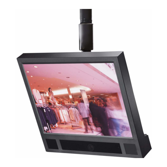
- Page 1 UMS Series Public View Monitor UMS-20xxxA and UMS-20xxxC Installation Manual...
-
Page 2: Important Safeguards
9. Safety Check - Upon completion of servicing or repairs to the unit, ask the service technician to perform safety checks to ensure proper operating condition. F01U029703 | 1.0 | 2006.07 Bosch Security Systems, Inc. - Page 3 IEC Publication 227 or IEC Publica- temperature requirements. tion 245. 2. Mechanical Loading - When rack-mounting the equip- ment, ensure that a hazardous condition is not created by uneven mechanical loading. Bosch Security Systems, Inc. F01U029703 | 1.0 | 2006.07...
-
Page 4: Safety Precautions
WARNING: This is a Class A product. In a domestic environ- ment, this product may cause radio interference, in which case, the user may be required to take adequate measures. F01U029703 | 1.0 | 2006.07 Bosch Security Systems, Inc. - Page 5 Avertissement : Ce produit est un appareil de Classe A. Son utilisation dans une zone résidentielle risque de provoquer des interférences. Le cas échéant, l’utilisateur devra prendre les mesures nécessaires pour y remédier. Bosch Security Systems, Inc. F01U029703 | 1.0 | 2006.07...
- Page 6 Cordons d’alimentation 220-240 V, 50 Hz Les cordons d’alimentation 220-240 V, 50 Hz, d’entrée ou de sortie, doivent être conformes à la dernière version de la publi- cation IEC 227 ou IEC 245. F01U029703 | 1.0 | 2006.07 Bosch Security Systems, Inc.
- Page 7 Bosch Security Systems, Inc. F01U029703 | 1.0 | 2006.07...
-
Page 8: Document Conventions
For additional information, see www.boschsecurity.com Related Publications Refer to the latest Bosch Security Systems Databook for the most up-to-date datasheets. To obtain a copy of the Databook, please contact your local Bosch representative. You can also visit the Bosch Security Systems World Wide Web site at: http://www.boschsecurity.com to view a current listings of our publications. - Page 9 | UMS Series F01U029703 | 1.0 | 2006.07 Installation Manual Bosch Security Systems, Inc.
-
Page 10: Table Of Contents
Installing the UMS Series Power Mounting Power Connection Video Connections Remote Control Battery Installation Monitor Remote Control Functions (Bosch) Monitor Remote Control Operating Modes Navigating the Monitor On-screen Display (OSD) Monitor Remote Control On-screen Display Menus Input Select Menu Using the Card Reader... - Page 11 Card reader does not display images 9.12 Monitor does not display AUTO or AUX video when turned on UMS Ordering Information 10.1 Power Supply 10.2 Mounting Options 10.3 Replacement Parts Specifications F01U029703 | 1.0 | 2006.07 Installation Manual Bosch Security Systems, Inc.
-
Page 12: Unpacking
This equipment should be unpacked and handled with care. If an item appears to have been damaged in shipment, notify the shipper. Verify that all parts shown in the Parts List are included. If any items are missing, notify your Bosch Security Systems Sales or Customer Ser- vice Representative. -
Page 13: Description
The UMS Series also features feed-through wiring and a button-less housing, to minimize unauthorized tampering, and a remote control to control the optional card reader. See Section 4, Monitor Remote Control Functions (Bosch), on page 6 for more information. General Features The UMS Series features a 20.1-inch LCD flat-panel monitor with either a high resolution color... -
Page 14: Installing The Ums Series
UMS Series housing. The following illustration details the mounting hole patterns on the back of the UMS monitor: 17.88 8.94 3.94 1.97 2.95 1.48 6.96 8.13 8.97 8.28 Fig. 3.1 UMS Series Mounting Hole Pattern Bosch Security Systems, Inc. Installation Manual F01U029703 | 1.0 | 2006.07... -
Page 15: Power Connection
To connect the camera to a monitoring station, attach a coax cable to the Video Out connec- tor on the unit to the input connector of the external monitor/recorder. NOTICE! UMS models that feature an internal card reader do not include a Video In connector. F01U029703 | 1.0 | 2006.07 Installation Manual Bosch Security Systems, Inc. -
Page 16: Remote Control Battery Installation
Fig. 3.2 Battery Installation Slide the battery cover back into place. NOTICE! Replace batteries when required or at least once a year. Dispose of used batteries properly. Bosch Security Systems, Inc. Installation Manual F01U029703 | 1.0 | 2006.07... -
Page 17: Monitor Remote Control Functions (Bosch)
| Monitor Remote Control Functions (Bosch) UMS Series Public View System Monitor Remote Control Functions (Bosch) This section details the functions and the usage of the Bosch remote control. Button Function AUTO Switches between images from the auxiliary video to the surveillance video when motion is detected. -
Page 18: Monitor Remote Control Operating Modes
Use the Bosch remote control to make any necessary adjustments to the UMS. To navigate the set up menus, follow the steps below: Power on the unit by aiming the Bosch remote control at the bottom portion of UMS and press the ON button. -
Page 19: Video Menu
| Monitor Remote Control Functions (Bosch) UMS Series Public View System 4.3.1 Video Menu The Video menu allows you to customize the screen by adjusting the Sharpness, Brightness, Backlight, Contrast, Color, and Tint from a range of 0-100 . -
Page 20: Input Select Menu
All other input selections causes the UMS to enter the Power Save mode. In this case, do the following: Press the Power On button on the Bosch remote control. When the monitor displays the message DPMS Power Save Mode, press MENU again. -
Page 21: Using The Card Reader
UMS. – Utilize a digital camera to take photos; then transfer the memory card to the UMS. F01U029703 | 1.0 | 2006.07 Installation Manual Bosch Security Systems, Inc. - Page 22 NOTICE! On units supplied with a card reader, a SanDisk remote control is included. This remote control allows additional features to be controlled via the card reader. 5.2.3 Removing the Flash Memory Card To remove your flash memory card, pull the card out. Bosch Security Systems, Inc. Installation Manual F01U029703 | 1.0 | 2006.07...
-
Page 23: Card Reader Remote Control Functions (Sandisk®)
Navigates left Card Reader On-screen Display Menu Selections NOTICE! See Section 4, Monitor Remote Control Functions (Bosch), on page 6 for information on installing the batteries for your SanDisk remote control. Use the memory card reader remote control to make any necessary adjustments to the images stored on your memory card. -
Page 24: Card Reader Menu Selections
6.2.2 Display Photo Info Menu The Display Photo Info menu allows you to display the image information (date, time, size of file, and resolution). Fig. 6.2 Photo Info Menu Bosch Security Systems, Inc. Installation Manual F01U029703 | 1.0 | 2006.07... - Page 25 To preview the changes, press the MENU/SELECT button on the memory card reader remote control and then select the Exit option on the screen. Press the NEXT or PREVIOUS button to view each image. Fig. 6.5 Picture Position Menu F01U029703 | 1.0 | 2006.07 Installation Manual Bosch Security Systems, Inc.
-
Page 26: Language Menu
The Language menu allows you to switch languages for the card reader OSD. Fig. 6.6 Language Menu 6.2.7 Exit Menu The Exit menu allows you to exit the screen. To resume playing your images, press PLAY/ SLIDE SHOW. Bosch Security Systems, Inc. Installation Manual F01U029703 | 1.0 | 2006.07... -
Page 27: Configuring Motion Detection
PIR sensor is used to control switching in the AUTO mode. Press the AUTO button on the Bosch remote control. If you have a memory card inserted, the UMS displays the image(s) on the screen (otherwise the screen is black). For informa- tion on how to insert a memory card see Section 5.2.2, Inserting the Flash Memory Card... -
Page 28: Camera Tilt And Pivot Adjustments
Fig. 8.1 High-resolution, Color Camera Adjustment Points Ref. # Description Tilt adjustment; thumb nut Pivot point Rotate adjustment dial; used to square camera once adjustments have been made Bosch Security Systems, Inc. Installation Manual F01U029703 | 1.0 | 2006.07... -
Page 29: Dip Switch Location For The High-Resolution Color Camera
Shutter speed to be fixed at 1/100 second Normal position Backlight Set to this position when a strong light is in the background Compensation Normal position (BLC) Synchronization Internal Synchronization mode Mode L.L. Linelock mode F01U029703 | 1.0 | 2006.07 Installation Manual Bosch Security Systems, Inc. -
Page 30: Wide Dynamic Range (Wdr) Series Camera
Fig. 8.4 Wide Dynamic Range (WDR) Camera Dip Switch Location The following chart explains the selectable dip switches for the Wide Dynamic Range (WDR) Camera: Camera is in WDR mode Bosch Security Systems, Inc. Installation Manual F01U029703 | 1.0 | 2006.07... -
Page 31: Focusing The Camera
Power Save Mode. When the sensor detects light, the monitor automatically switches to the ON mode. NOTICE! The looping output video is still active so that external recording continues in the Power Save mode. F01U029703 | 1.0 | 2006.07 Installation Manual Bosch Security Systems, Inc. -
Page 32: Troubleshooting
Option Switches (see Figure 9.2 on page 22 for details) RS-232 (factory use only) LCD Monitor Video Aux Video In Internal Camera Video Out Loop Video In Reserved for future use Power Connector Phase Control Power to Camera Bosch Security Systems, Inc. Installation Manual F01U029703 | 1.0 | 2006.07... -
Page 33: Screen Flickers
Below is a table of maximum distances that the specified wire gauges can traverse with a 24 V transformer: Gauge Distance Gauge Distance 20 AWG 40 ft 14 AWG 170 ft 18 AWG 70 ft 12 AWG 270 ft 16 AWG 100 ft F01U029703 | 1.0 | 2006.07 Installation Manual Bosch Security Systems, Inc. -
Page 34: No Video Displayed
Power LED to turn the monitor OFF; this action saves the settings. Press the POWER button again to re-activate the monitor. If there is still no video displayed, contact your Bosch Security Systems representative or customer service. Only displays Power Save mode In this case, the Video option on the Input Select menu may be OFF. -
Page 35: Remote Control Does Not Activate The Monitor
This kit contains the Bosch branded remote, a SanDisk remote, and batteries. If the Bosch remote control is not available, it is possible to navigate through the screens by using the buttons on the back of your unit. See the image below for the location for the these buttons: Fig. -
Page 36: Memory Card Images Appear Stretched And Out Of Proportion
To confirm the true size of your photo, follow these steps: Press either the AUTO or AUX button on the Bosch remote control. Press the PAUSE button and then press the MENU/SELECT button on the SanDisk remote control. -
Page 37: Monitor Does Not Display Auto Or Aux Video When Turned On
9.12 Monitor does not display AUTO or AUX video when turned on – Ensure that the MEM button on the monitor remote control (Bosch) was used to save the operating mode. – Press the AUTO or AUX button on the monitor remote control (Bosch). If you pressed the On/Off buttons on either remote, the display always returns to the CAM mode. -
Page 38: Ums Ordering Information
Camera Replacement Kit: One (1) wide dynamic camera with 3.8–9.5 mm lens 315 5531 925 Remote Control Replacement Kit: One (1) Monitor Remote Control (Bosch) One (1) Memory Card Reader Remote Control (SanDisk) Four (4) AAA Batteries Bosch Security Systems, Inc. -
Page 39: Specifications
Compatible Flash Memory Card Formats: SmartMedia™ (SM), Secure Digital/MultiMedia Card (SD/MMC), Compact Flash™ (CF), Sony Memory Iris Range f/1.2-360 f/1.3-360 Stick™ (MS) Iris/Shutter DC Auto Iris Format 1/4 in. 1/3 in. F01U029703 | 1.0 | 2006.07 Installation Manual Bosch Security Systems, Inc. - Page 40 (114.3 x 127 x 91.44 mm) Material Steel case Finish Powder-coated white Input Power Connector Detachable, 3-wire IEC grounded plug Output Power Connector Screw terminal block Safety UL, cUL Bosch Security Systems, Inc. Installation Manual F01U029703 | 1.0 | 2006.07...
- Page 41 | Specifications UMS Series Public View System F01U029703 | 1.0 | 2006.07 Installation Manual Bosch Security Systems, Inc.
- Page 42 Backlight compensation 18 Exit 15 Backlight option 8 Language 15 Blending option 8 Picture Position 14 Bosch remote control 16 Slide Show Delay 14 Brightness option 8 TV Screen Display 14 Mirroring option 9 CAM mode 7 Misc. menu 9...
- Page 43 Select 13 Select Memory Card menu 13 Sharpness option 8 Slide Show Delay menu 14 Specifications 2 power 3 Synchronization mode 22 System Power LED 21 System Pulse LED 21 F01U029703 | 1.0 | 2006.07 Installation Manual Bosch Security Systems, Inc.
- Page 44 5600 JB Eindhoven Singapore 577180 Phone: +31 40 2577 200 Phone +65 6319 3450 Phone +1 800 289 0096 Fax: +31 40 2577 202 +65 63139 3499 +1 585 223 9180 nl.securitysystems@bosch.com www.boschsecurity.com www.boschsecurity.us www.boschsecurity.nl © Bosch Security Systems, Inc., 2006 www.boschsecurity.com...