
Related Manuals for Avaya WLAN 2332


Summary of Contents for Avaya WLAN 2332
-
Page 1: Installation Guide
WLAN Series 2332 Access Point Installation Guide Avaya WLAN 2300 Release 7.0 Document Status: Standard Document Number: NN47250-307 Document Version: 02.02... - Page 2 Avaya does not guarantee that these links will work all the time and has no control over the availability of the linked pages.
- Page 3 2332-A1, 2332-A2, 2332-A3, 2332-A4, 2332-A5, 2332-A6, 2332-E1, 2332-E2, 2332-E3, 2332-E4, 2332-E5, 2332-E6, 2332-E7, 2332-E8, 2332-E9, 2332-J1. Federal Communications Commission (FCC) Compliance Notices This section includes the following FCC statements for the WLAN 2332-A1 and related Series 2332 access points: • FCC ID: RVW2332 (Applies to 2332-A1) •...
-
Page 4: Canadian Ic Statement
Any changes or modifications not expressly approved by the party responsible for compliance could void the user's authority to operate this equipment. Contact Avaya for a list of approved 2.4 GHz and 5.0 GHz external antennas. This device must be operated with the CAT-5 Ethernet cable installed on each activated Ethernet Port of a Series 2332 access point to ensure compliance with the Class B emissions standards. -
Page 5: Declaration Of Conformity
Broadband Radio Access Networks (BRAN); 5 GHz high performance RLAN. Certifications are harmonized to the EN standards covering essential requirements under article 3.2 of the R&TTE Directive. Compliance includes testing with antennas as specified in attached table. SAR: EN 50385:2002 NN47250-307 Avaya WLAN 2332 Access Point Installation Guide... - Page 6 2332, overholder de væsentlige krav og øvrige relevante krav i direktiv 1999/ 5/EF. English English Hereby, Avaya declares that this WLAN Radio Model 2332, is in compliance with the essential requirements and other relevant provisions of Directive 1999/5/EC. Estonia Eesti Käesolevaga kinnitab Avayaseadme WLAN Radio Model 2332, vastavust...
- Page 7 Directiva 1999/5/CE. Romania Român Astfel, Avaya declarã acel acest WLAN Radio Model 2332, este în conformitate cu cerinþele necesare ºi proviziile alte semnificative de Directive 1999 5 EC. NN47250-307 Avaya WLAN 2332 Access Point Installation Guide...
- Page 8 In Italy and Latvia the end-user must apply for a license from the national spectrum authority to operate this device outdoors. Please consult the Avaya WLAN 2300 Series Outdoor Solutions Guide for further infor- mation regarding restrictions and operating conditions for outdoor configurations.
- Page 9 In Italy the end-user must apply for a license from the national spectrum authority to operate this device outdoors. Please consult the Avaya WLAN 2300 Series Outdoor Solutions Guide for further information regarding restrictions and operating conditions for outdoor configurations.
-
Page 10: Korea Mic Compliance Statement
Without permission granted by the NCC, any company, enterprise, or user is not allowed to change frequency, enhance transmitting power or alter original characteristic as well as performance to an approved low power radio-frequency device. NN47250-307 Avaya WLAN 2332 Access Point Release 7.0 Standard 02.02 July 2010... - Page 11 4.7.7 Manufacturers of U-NII devices are responsible for ensuring frequency stability such that an emission is maintained within the band of operation under all conditions of normal operation as specified in the user manual. NN47250-307 Avaya WLAN 2332 Access Point Installation Guide...
-
Page 12: External Antenna Statement
For a complete listing of the authorized antennas for use with this product, visit http://www.avaya.com/support. In order to ensure continued compliance, use of an antenna not on the Avaya approved antenna list is not allowed without specific authorization from Avaya. -
Page 13: Country Specific External Antenna Restrictions
Country Specific External Antenna Restrictions The following list of countries cannot use the Avaya approved antennas listed in the table. Use of these antennas would violate the local regulatory rules and approved certifications for that country or operation is not allowed in the specified frequency bands. - Page 14 NN47250-307 Avaya WLAN 2332 Access Point Release 7.0 Standard 02.02 July 2010...
-
Page 15: Table Of Contents
Avaya WLAN 2332 Series System ........ - Page 16 16 Contents Series 2332 Access Point Region Lock Mechanism ....57 IEEE 802.11a/b/g Channel Designations: ....... 58 2400 - 2483.5 MHz band .
-
Page 17: Customer Service
Customer service Visit the Avaya Web site to access the complete range of services and support that Avaya provides. Go to www.avaya.com or go to one of the pages listed in the following sections. Navigation Getting technical documentation” on page 17 Getting product training”... - Page 18 18 Customer service NN47250-307 (Version 02.02)
-
Page 19: Introducing The Avaya Wlan 2300 System
Avaya WLAN 2332 Series System ........ -
Page 20: Avaya Wlan 2332 Series System
20 Introducing the Avaya WLAN 2300 System Avaya WLAN 2332 Series System The Avaya WLAN 2300 System is an enterprise-class WLAN solution that seamlessly integrates with an existing wired enterprise network. The Avaya system provides secure connectivity to both wireless and wired users in large environments such as office buildings, hospitals, and university campuses. -
Page 21: Documentation
● Avaya WLAN—Security Switch 2300 Series Installation and Basic Configuration Guide: Instructions and specifications for installing a WSS in an Avaya WLAN 2300 System, and basic instructions for deploying a secure IEEE 802.11 wireless service ● Avaya WLAN—Series 2332 Access Point Installation Guide: Instructions and specifications for installing... -
Page 22: Text And Syntax Conventions
High voltage. This situation or condition can cause injury due to electric shock. Note. This information is of special interest. Text and syntax conventions Avaya manuals use the following text and syntax conventions: Convention Monospace text Sets off command syntax or sample commands and system responses. -
Page 23: Ap Overview
External hardware features ..........24 An Avaya Access Point (AP) provides IEEE 802.11 wireless access to the network. APs are designed for use with an Avaya WLAN—Security Switch (WSS). -
Page 24: External Hardware Features
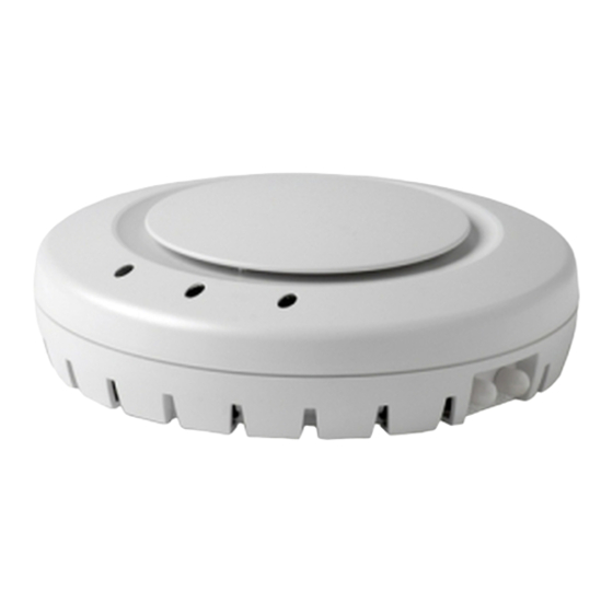
24 AP overview External hardware features Figure 1 Figure 2 show the external hardware features of the Series 2332 access point. Figure 1. AP Model —Top View Diameter 16.76 cm (6.6 inches) Height 6.10 cm (2.4 inches) Figure 2. AP Model Series 2332 —Bottom View External antenna Kensington security connectors... -
Page 25: Cable Ports
The AP receives power and data through the RJ-45 ports. Use a Category 5 (Cat 5) cable with straight-through signaling and standard RJ-45 connectors to connect an AP to an WSS or other device in the network. The Series 2332 access point supports 802.3af, and also can receive PoE from Avaya switches and Avaya-approved power injectors. - Page 26 26 AP overview The AP has LEDs that provide status information of the device. Figure 3 shows the locations of the LEDs. Table 1 describes the LEDs. Figure 3. Health and Radio LEDs—Series 2332 access point Radio 1 LED Radio 2 LED Health LED Table 1.
- Page 27 • The radio has failed. Unlit Means one of the following: • Radio is disabled. • Radio is enabled, but no clients are associated with the radio and there is no traffic activity. Avaya WLAN Series 2332 Access Point Installation Guide...
- Page 28 28 AP overview NN47250-307 (Version 02.02)
-
Page 29: Installing And Connecting A Series 2332 Access Point
Before installing an AP, you might need to generate a network plan and an AP work order with WLAN Management Software . (See “WLAN Management software network plan and work orders” on page 32.) Avaya WLAN Series 2332 Access Point Installation Guide... -
Page 30: Unpacking An Ap
Three adhesive rubber feet ● One documentation pack that includes the following documents: ● Avaya WLAN Series 2332 Access Point Quick Installation Guide ● Avaya WLAN 2300 Series Access Point Mounting Template ● Avaya WLAN 2300 Series Outdoor Solution Guide... - Page 31 Open the carton and carefully remove the contents, if you have not already done so. Place the packing materials back in the carton and save the carton. Verify that you received each item in the previous list. If any item is missing or damaged, contact Avaya. Avaya WLAN Series 2332 Access Point Installation Guide...
-
Page 32: Installation Requirements And Recommendations
If you are using the WLAN Management Software to plan your Avaya Mobility System installation, you might want to create and verify a network plan for the entire Avaya network installation and generate an AP work order, before installing any access points. A network plan and the AP work orders provide the following information about AP installation and configuration: ●... -
Page 33: Additional Radio Safety Advisories
FCC-certified equipment. Avaya Series 2332 access point products meet the uncontrolled environmental limits found in OET-65 and ANSI C95.1-1991, if proper installation procedures are followed. To ensure compliance with these exposure requirements, this device must be installed in such a manner as to maintain a minimum of 20 cm separation distance between the radiating element(s) and all persons. - Page 34 10/100 Ethernet straight-through wiring. Pins 4, 5, 7, and 8 are used when Avaya Power over Ethernet (PoE) is enabled on the port. RD stands for Receive Data and TD stands for Transmit Data.
-
Page 35: Installing A Series 2332 Access Point
T-bar clamp Box cutter Small screwdriver (3-mm or 1/ 8-inch) Junction box Junction box Two #6-32 x 1-inch machine screws Yes Universal mounting bracket Small screwdriver (3-mm or 1/ 8-inch) #2 Phillips-head screwdriver Avaya WLAN Series 2332 Access Point Installation Guide... -
Page 36: Suspended Ceiling Installation-Flush Ceiling Tiles
36 Installing and connecting a Series 2332 Access Point Table 3. Required Mounting Hardware and Tools— Series 2332 access point (continued) Included with the Mounting Option Required Hardware and Tools Product Solid wall or ceiling Two #6 sheet metal screws and two drywall anchors Universal mounting bracket Hammer... - Page 37 Unlock hole on the AP as shown in Figure Caution! To avoid damage to the AP’s lock mechanism or electronic components, do not use excessive force when inserting a tool into the Unlock or Lock hole. Avaya WLAN Series 2332 Access Point Installation Guide...
- Page 38 38 Installing and connecting a Series 2332 Access Point Figure 7. Step 5—Unlocking the Bracket Remove the bracket as shown in Figure 8 on page Figure 8. Step 6—Removing the Bracket Install the universal mounting bracket as follows onto the T-bar or T-bar clamp: As shown in Figure 9, place the universal mounting bracket against the T-bar or...
- Page 39 Insert the Cat-5 cable into the connector: 10 Install the Kensington lock (optional). Loop the Kensington lock’s cable around an object that cannot be moved or damaged by a person pulling on the cable. Avaya WLAN Series 2332 Access Point Installation Guide...
- Page 40 40 Installing and connecting a Series 2332 Access Point Insert the key into the Kensington lock. Insert the Kensington lock into the security slot on the AP. Rotate the key right or left to secure the lock to the AP. Pull on the lock to verify that it is secured to the AP.
-
Page 41: Suspended Ceiling Installation-Drop Ceiling Tiles
Slide each half of the clamp onto the T-bar so that the clamp lip is fully on the T-bar. Slide the two halves of the clamp toward each other until the tabs are inserted completely into the holes and the clamp fits snugly on the T-bar. Avaya WLAN Series 2332 Access Point Installation Guide... - Page 42 42 Installing and connecting a Series 2332 Access Point Figure 13 shows an example for a 23.9-mm (15/16-inch) T-bar. Figure 14 shows an example for a 15.9-mm (5/8-inch) T-bar. Figure 13. Step 3—Installing the T-bar Clamp for a 23.9-mm (15/16-inch) T-bar T-bar Slide together T-bar clamp halves...
- Page 43 Rotate the universal mounting bracket clockwise until the flanges snap into place on the T-bar clamp as shown in Figure 18 on page Avaya WLAN Series 2332 Access Point Installation Guide...
- Page 44 44 Installing and connecting a Series 2332 Access Point Figure 17. Step 6—Top View Universal mounting bracket T- bar T-bar clamps (attached to T-bar) Port connector opening (Viewed from above ceiling tiles, looking down.) Figure 18. Step 6—Bottom View Port connector Universal mounting bracket opening T-bar...
- Page 45 11 Lock the AP onto the bracket by inserting the 3-mm or 1/8-inch screwdriver into the Lock hole on the access point as shown in Figure Caution! To prevent possible damage to the AP, make sure the device is fully locked onto the bracket before releasing it. Avaya WLAN Series 2332 Access Point Installation Guide...
-
Page 46: Junction Box Installation
46 Installing and connecting a Series 2332 Access Point Figure 20. Step 10—Locking the Bracket Lock T-bar 12 To ensure that the AP is fully locked onto the bracket, gently pull down on the access point and attempt to rotate it from side to side. If the access point comes off the bracket, relock the device onto the bracket as described in step 11 on page... - Page 47 Insert the #6-32 x 1-inch machine screws in the universal mounting bracket’s screw holes, and use a #2 Phillips-head screwdriver to tighten them. Avaya WLAN Series 2332 Access Point Installation Guide...
- Page 48 48 Installing and connecting a Series 2332 Access Point Figure 23. Step 3—Placing the Bracket on the Junction Box Junction box Port connector opening Pull the Cat-5 cable about 15 cm (about 6 inches) out of the junction box and through the port connector opening to create enough slack to insert the cable into the port connector.
-
Page 49: Solid Wall Or Ceiling Installation
If you plan to route the Cat-5 cable externally along the wall or ceiling, mark ❍ the locations of both the center screw hole and the screw hole by the port connector opening. Avaya WLAN Series 2332 Access Point Installation Guide... - Page 50 50 Installing and connecting a Series 2332 Access Point If you plan to route the Cat-5 cable through a hole in the wall or ceiling, mark ❍ the location of the center screw hole only. You cannot use the screw hole by the port connector opening if you cut a hole for the opening.
- Page 51 Do not insert screws in the four holes on the edges of the bracket. (These are the holes indicated by the dashed lines in Figure 27.) The AP fits into these holes. They are not screw holes. Avaya WLAN Series 2332 Access Point Installation Guide...
- Page 52 52 Installing and connecting a Series 2332 Access Point Figure 27. Steps 5 and 6—Bracket Placement on Solid Wall or Ceiling As shown in Figure 28, insert the Cat-5 cable into the connector: Figure 28. Step 8—Cable Placement Cable Universal mounting bracket NN47250-307 (Version 02.02)
- Page 53 12 If the other end of the Cat-5 cable is not already connected and the link activated, then go to “Connecting an AP to a WSS” on page 54. Otherwise, go to “Verifying AP health” on page Avaya WLAN Series 2332 Access Point Installation Guide...
-
Page 54: Connecting An Ap To A Wss
WSS. You can use the CLI or WLAN Management Software to configure an AP or Distributed AP connection. (See the Avaya WLAN Security Switch 2300 Series Configuration Guide or the Avaya WLAN Management Software 2300 Series User Guide.) Figure 30 shows how to insert a Cat-5 cable into a 10/100 Ethernet port on a WSS. - Page 55 The 10/100 Ethernet ports on a WSS are configured as wired network ports by default. You or the system administrator must change the port type for a WSS port directly connected to an AP to activate the link. (See the Avaya WLAN 2300 Series—Security Switch Installation and Basic Configuration Guide.)
-
Page 56: Verifying Ap Health
56 Installing and connecting a Series 2332 Access Point Verifying AP health After you install the AP and enable PoE on the Ethernet cable connected to the AP, you can easily verify the AP’s status by observing the LEDs, particularly the health LED. (See Figure 3 on page 26.) The health or LINK LED indicates whether the AP is ready for operation. -
Page 57: Series 2332 Access Point Region Lock Mechanism
2.4 : 5.1 2332-E8 13 : 7 2.4 : 5.7 2332-E9 13 : NO 5 2.4 : NO 5.0 GHz Specials Specials Specials 2332-J1 14 : 1, 2 2.4 : 5.1, 5.2 Avaya WLAN Series 2332 Access Point Installation Guide... -
Page 58: Ieee 802.11A/B/G Channel Designations
58 Series 2332 Access Point Region Lock Mechanism IEEE 802.11a/b/g Channel Designations: 2400 - 2483.5 MHz band IEEE Mode 11b/g 11b/g 11b/g 11b/g 11b/g 11b/g 11b/g 11b/g 11b/g 11b/g 11b/g Channel Number Frequency [GHz] 2.412 2.417 2.422 2.427 2.432 2.437 2.442 2.447 2.452 2.457 2.462 IEEE Mode 11b/g 11b/g 11b/g Channel Number... -
Page 59: 5.15 - 5.35 Ghz Bands
1, 2, 3, 4, 5, 6, 7, 8, 9, 10, 11, (802.11b/g): 12, 13 5.0 GHz bands 36, 40, 44, 48, 52, 56, 60, 64, (802.11a): 100, 104, 108, 112, 116, 136, Avaya WLAN Series 2332 Access Point Installation Guide... - Page 60 60 Series 2332 Access Point Region Lock Mechanism NN47250-307 (Version 02.02)
-
Page 61: External Antennas
Lower cost of coverage – External antennas improve overall system ❍ efficiency by effectively directing available energy to where it’s needed. This ensures overall system utility is maximized for any installation. Avaya WLAN Series 2332 Access Point Installation Guide... - Page 62 62 External Antennas The WLAN 2300 series external antennas are the only external antennas certified by Avaya for use with WLAN 2300 systems. WLAN Series 2332 Access Points outfitted with non-certified external antennas are not supported under support agreements. The WLAN 2300 system must be upgraded to WSS Software v6.0 (or later) and WMS v6.0 (or later) in order to support Series 2332 access points and their associated external antennas.
-
Page 63: External Antenna Selector Guide For The Series 2332 Access Points For Indoor Operation
DR4000074E6 24203 WLAN Omni-directional Patch Panel Ceiling Mount Antenna with an average gain of 0.0 dBi and a 3-foot cable with a Reverse SMA connector. For use in contemporary in-building WLAN applications. Avaya WLAN Series 2332 Access Point Installation Guide... - Page 64 64 External Antennas SQ2405DDN36RSM DR4000073E6 24403 WLAN Bi-directional Patch Panel Ceiling Mount Antenna with an average gain of 4.5 dBi and a 3-foot cable with a Reverse SMA connector. For use in Offices, Shopping Complexes, Transportation Terminals, Educational Campuses, Hallways, and Tunnels. S2409PN36RSM DR4000076E6 24883...
- Page 65 5.725 - 5.85 GHz. It is 7" in height, and has a 3-foot cable with a Reverse SMA connector. For use in Warehouses, Auditoriums, Shopping Malls, industrial complexes and other locations. Avaya WLAN Series 2332 Access Point Installation Guide...
- Page 66 66 External Antennas S51514WPN36RSM DR4000071E6 5133 WLAN Directional Patch Panel Antenna with an average gain of 13.1 dBi from 5.15 - 5.25 GHz, 13.0 dBi from 5.25 - 5.35 GHz, 13.0 dBi from 5.470 - 5.725 GHz and 12.9 dBi from 5.725 - 5.85 GHz.
-
Page 67: Antenna Selection Decision Trees
For more information see “Dual-band, Tri-mode 802.11a/b/g Spatial Diversity Antenna” in the Antenna Descriptions section. Avaya WLAN Series 2332 Access Point Installation Guide... - Page 68 68 External Antennas Figure 31. 5 GHz Antennas NN47250-307 (Version 02.02)
-
Page 69: Dual-Band 802.11A/B/G (2.4/5.0 Ghz)
Order Number: DR4000069E6 ● Cushcraft Model SQ5153WPN36RSM ● 5.15 - 5.25 GHz, 3.2 dBi Peak Gain ● 5.25 - 5.35 GHz, 2.5 dBi Peak Gain ● 5.470 - 5.725 GHz, 1.6 dBi Peak Gain Avaya WLAN Series 2332 Access Point Installation Guide... - Page 70 70 External Antennas ● 5.725 - 5.85 GHz, 0.1 dBi Peak Gain ● Ultra-compact, low profile design with minimum visual impact ● Ideal for large indoor open spaces and locations with high ceilings ● Measures 2” x 2” x ¾” NN47250-307 (Version 02.02)
- Page 71 External Antennas 71 Avaya WLAN Series 2332 Access Point Installation Guide...
- Page 72 72 External Antennas NN47250-307 (Version 02.02)
- Page 73 Rugged design suitable for industrial environments ● Ceiling, I-beam and mast mounting options ● Suitable for large indoor open spaces and locations with high ceilings ● Slim aspect measuring 11.5” x 1” Avaya WLAN Series 2332 Access Point Installation Guide...
- Page 74 74 External Antennas NN47250-307 (Version 02.02)
- Page 75 External Antennas 75 Avaya WLAN Series 2332 Access Point Installation Guide...
- Page 76 76 External Antennas High-Gain Directional Panel Antenna Order Number: DR4000071E6 ● Cushcraft Model S51514WPN36RSM ● 5.15 - 5.25 GHz, 13.1 dBi ● 5.25 - 5.35 GHz, 13.0 dBi Peak Gain ● 5.470 - 5.725 GHz, 13.0 dBi Peak Gain ● 5.725 - 5.85 GHz, 12.9 dBi Peak Gain ●...
- Page 77 External Antennas 77 Avaya WLAN Series 2332 Access Point Installation Guide...
- Page 78 78 External Antennas NN47250-307 (Version 02.02)
-
Page 79: 13 High-Gain Directional Panel Antenna
Wall or pole mounting available for 1.5" to 3.5" diameter pole giving up to 15° of down-tilt ● Symmetrical and uniform 90 degree H-plane and 5.5 degree E-plane patterns ● Measures 2.74" in diameter x 24.6" Long Avaya WLAN Series 2332 Access Point Installation Guide... - Page 80 80 External Antennas NN47250-307 (Version 02.02)
- Page 81 External Antennas 81 Avaya WLAN Series 2332 Access Point Installation Guide...
- Page 82 82 External Antennas NN47250-307 (Version 02.02)
- Page 83 External Antennas 83 Avaya WLAN Series 2332 Access Point Installation Guide...
- Page 84 84 External Antennas NN47250-307 (Version 02.02)
- Page 85 External Antennas 85 Avaya WLAN Series 2332 Access Point Installation Guide...
- Page 86 86 External Antennas 14 High-Gain Directional Panel Antenna Order Number: DR4000091E6 ● Cushcraft Model SR49120DAN36RS ● 5.15 - 5.25 GHz, 10.0 dBi Peak Gain ● 5.25 - 5.35 GHz, 9.9 dBi Peak Gain ● 5.470 - 5.725 GHz, 9.6 dBi Peak Gain ●...
- Page 87 External Antennas 87 Avaya WLAN Series 2332 Access Point Installation Guide...
- Page 88 88 External Antennas NN47250-307 (Version 02.02)
- Page 89 External Antennas 89 Avaya WLAN Series 2332 Access Point Installation Guide...
- Page 90 90 External Antennas NN47250-307 (Version 02.02)
- Page 91 External Antennas 91 Avaya WLAN Series 2332 Access Point Installation Guide...
-
Page 92: Antenna Descriptions - 802.11B/G (2.4 Ghz) Antennas
92 External Antennas Antenna descriptions – 802.11b/g (2.4 GHz) antennas Omni-directional Colinear Dipole Antenna Order Number: DR4000088E6 ● Cushcraft Model S2403BPXN36RSM ● 2.4 - 2.5 GHz, 4.9 dBi Peak Gain ● Rugged housing suitable for industrial deployments ● Ideal for large open areas ●... - Page 93 External Antennas 93 ● Measures 11.5” x 1” Avaya WLAN Series 2332 Access Point Installation Guide...
- Page 94 94 External Antennas NN47250-307 (Version 02.02)
- Page 95 External Antennas 95 Avaya WLAN Series 2332 Access Point Installation Guide...
- Page 96 96 External Antennas Omni-directional Ceiling Panel Antenna Order Number: DR4000073E6 ● Cushcraft Model SQ2405DDN36RSM ● 2.4 - 2.5 GHz, 4.5 dBi Peak Gain ● Bi-directional, low profile ceiling antenna ● Paintable with light, non-metallic coating for custom color matching ● 3-foot cable ●...
- Page 97 External Antennas 97 Avaya WLAN Series 2332 Access Point Installation Guide...
- Page 98 98 External Antennas NN47250-307 (Version 02.02)
- Page 99 ● 2.4 - 2.5 GHz, 0.0 dBi Peak Gain ● Very uniform and symmetrical antenna pattern ● Well-suited for high-density deployments ● 3-foot cable ● Measures only 2” x 2” x 0.7” Avaya WLAN Series 2332 Access Point Installation Guide...
- Page 100 100 External Antennas NN47250-307 (Version 02.02)
- Page 101 External Antennas 101 Avaya WLAN Series 2332 Access Point Installation Guide...
- Page 102 102 External Antennas Directional Panel Antenna Order Number: DR4000075E6 ● Cushcraft Model S2406PN36RSM ● 2.4 - 2.5 GHz, 6.5 dBi Peak Gain ● Well-suited for wall mounted applications ● Good for hallways and corridors ● Easy to disguise or hide ●...
- Page 103 External Antennas 103 Avaya WLAN Series 2332 Access Point Installation Guide...
- Page 104 104 External Antennas NN47250-307 (Version 02.02)
- Page 105 2.4 - 2.5 GHz, 8.8 dBi Peak Gain ● Well-suited for wall mounted applications ● Good for hallways and corridors where multi-path and scattering can be a problem ● 3-foot cable ● Measures only 6” x 6” x 1.25” Avaya WLAN Series 2332 Access Point Installation Guide...
- Page 106 106 External Antennas NN47250-307 (Version 02.02)
- Page 107 External Antennas 107 Avaya WLAN Series 2332 Access Point Installation Guide...
- Page 108 108 External Antennas Directional Yagi Antenna Order Number: DR4000077E6 ● Cushcraft Model PC2415NA36RSM ● 2.4 - 2.5 GHz, 14.1 dBi Peak Gain ● Articulating mount for precise direction pointing ● Good for long and narrow zones like tunnels ● 3-foot cable ●...
- Page 109 External Antennas 109 Avaya WLAN Series 2332 Access Point Installation Guide...
- Page 110 110 External Antennas NN47250-307 (Version 02.02)
- Page 111 Uniform 120 degree H-plane and 14 degree E-plane pattern ● Wall or pole mounting options available ● Designed for long, wide coverage environments ● 3-foot cable ● Measures 23" x 3" x 2" Avaya WLAN Series 2332 Access Point Installation Guide...
- Page 112 112 External Antennas NN47250-307 (Version 02.02)
- Page 113 External Antennas 113 Avaya WLAN Series 2332 Access Point Installation Guide...
- Page 114 114 External Antennas 11 Directional Patch Panel Antenna Order Number: DR4000086E6 ● Cushcraft Model S241290PN36RSM ● 2.4 - 2.5 GHz, 12 dBi Peak Gain ● Uniform 90 degree H-plane and 17 degree E-plane pattern ● Tilt-mount available for precise direction pointing(shown) ●...
- Page 115 External Antennas 115 Horizontal Polarization BW = 90 Deg Avaya WLAN Series 2332 Access Point Installation Guide...
-
Page 116: 2.4/5.0 Ghz Dual Antenna
116 External Antennas 2.4/5.0 GHz Dual antenna 12 Dual-band, Tri-mode 802.11a/b/g Spatial Diversity Antenna Order Number: DR4000078E6 ● Cushcraft Model S24493DSN36RSM ● 2.4 - 2.5 GHz, 3.0 dBi Peak Gain ● 4.90 - 5.15 GHz, 4.0 dBi Peak Gain ● 5.15 - 5.25 GHz, 3.9 dBi Peak Gain 5.25 - 5.35 GHz, 3.2 dBi Peak Gain 5.470 - 5.725 GHz, 2.9 dBi Peak Gain... - Page 117 Each antenna port can be used individually for simultaneous 802.11a and 802.11b/g ● Well-suited for high data rate office applications ● 3-foot cable ● Measures 6.16” x .89” x 3.66” Azimuth Pattern for 2.4 GHz Avaya WLAN Series 2332 Access Point Installation Guide...
- Page 118 118 External Antennas Elevation Pattern 1 for 2.4 GHz NN47250-307 (Version 02.02)
- Page 119 External Antennas 119 Elevation Pattern 2 for 2.4 GHz Avaya WLAN Series 2332 Access Point Installation Guide...
- Page 120 120 External Antennas Azimuth Pattern for 5.0 GHz NN47250-307 (Version 02.02)
- Page 121 External Antennas 121 Elevation Pattern 1 for 5.0 GHz Avaya WLAN Series 2332 Access Point Installation Guide...
-
Page 122: Glossary Of Common Antenna Terminology
122 External Antennas Elevation Pattern 2 for 5.0 GHz Glossary of common antenna terminology The following glossary includes basic antenna terminology that can help in the selection and/or recommendation of a particular antenna. These terms are used throughout the remainder of the document: Omnidirectional (Omni) –... - Page 123 - as if looking directly at the antenna from the side. H-Plane graph – The horizontal plane graph shows the radiated antenna coverage pattern as a horizontal cross section - as if looking directly at the antenna from above. Avaya WLAN Series 2332 Access Point Installation Guide...
- Page 124 124 External Antennas NN47250-307 (Version 02.02)
-
Page 125: Ap Troubleshooting
WSS port connected to the AP. For an indirect connection through the network: • Configure a AP connection on a WSS. • Verify that an Avaya-approved PoE source is supplying power to the AP. Avaya WLAN Series 2332 Access Point Installation Guide... - Page 126 126 AP troubleshooting Table 5. Health LED States (Series 2332 Access Points) (continued) Health or LINK Diagnosis Remedy LED Appearance Slowly alternating AP is booting with an image Wait a few seconds for the boot process to green and amber received from a WSS.
-
Page 127: Ap Technical Specifications
Table 10 on page 131 lists the MAC address allocation scheme. (For specifications for the WSS, see the Avaya WLAN-Security Switch 2300 Series Configuration Guide.) Note. The Series 2332 access points are designed and approved to be used only with Avaya WLAN—Security Switch (WSS) models 2360/2361, and 2350. - Page 128 128 AP technical specifications Table 6. AP Mechanical and Compliance Specifications (continued) Specification Description Power over Ethernet 42 VDC to 57 VDC (46 VDC nominal) (PoE) IEEE 802.3af Status indicators Health/WSS and radio LEDs (For descriptions of the LEDs, see “Status LEDs”...
- Page 129 Association rates 11 Mbps, 5.5 Mbps, 2 Mbps, and 1 Mbps, with automatic fallback Modulation BPSK, QPSK, CCK Transmit power Based on the country of operation specified by the system administrator Avaya WLAN Series 2332 Access Point Installation Guide...
-
Page 130: Mac Addresses
130 AP technical specifications Table 9. 802.11g Radio Specifications Specification Description Antenna type Integrated omnidirectional with (2) radiating elements to allow for the use of diversity Antenna gain Internal: 3.86 dBi peak (Azimuth) and 2.48 dBi peak (Elevation) Frequency band 2.4 GHz to 2.4835 GHz based on country regulations Operating channels Based on the country of operation specified by the system... - Page 131 Addresses end in even numbers. The first BSSID is equal to the AP’s base MAC address. The next BSSID is equal to the AP’s base MAC address + 2, and so on. Avaya WLAN Series 2332 Access Point Installation Guide...
- Page 132 132 AP technical specifications NN47250-307 (Version 02.02)
-
Page 133: Translated Caution Statement, Warning Conventions And Warning Messages
The WLAN Access Point 2332 Series radios are disabled by default and can be enabled only by a system administrator using the WSS. Attention! Les communications radios points d'accès WLAN 2332 Série de sont désactivées par défaut et peuvent être activées uniquement par un administrateur système utilisant le WSS. Achtung! Der WLAN Access Point 2332 Familie Radios sind standardmäßig ausgeschaltet und... -
Page 134: Warning Conventions
134 Translated caution statement, warning conventions and warning messages Warning conventions Warning! This situation or condition can cause injury. Avertissement! Cette situation ou condition peut entraîner un risque de blessure. Warnung! Diese Situation oder dieser Umstand kann zu Verletzungen führen. Advertencia! Esta situación o condición puede causar lesiones. -
Page 135: Qualified Service Personnel Warning
Leia e siga todos os avisos e instruções destacados no produto ou que façam parte da documentação. Avviso! L'installazione deve essere eseguita esclusivamente da personale qualificato. Leggere e seguire tutti gli avvisi e le istruzioni presenti sul prodotto o inclusi nella documentazione. Avaya WLAN Series 2332 Access Point Installation Guide... -
Page 136: Radio Safety Warnings
136 Translated caution statement, warning conventions and warning messages Radio safety warnings Warning! Install this device in such a manner as to maintain a minimum of 20 cm (7.9 inches) separation distance between the radiating element(s) and all persons. This safety warning conforms with FCC radio frequency exposure limits. - Page 137 Non utilizzare il punto di accesso nelle vicinanze di involucri esplosivi non schermati o in qualsiasi ambiente in cui siano presenti sostanze esplosive, a meno che il dispositivo non sia stato modificato per tale uso da personale qualificato. Avaya WLAN Series 2332 Access Point Installation Guide...
- Page 138 138 Translated caution statement, warning conventions and warning messages Warning! Do not touch or move the access point when the antennas are transmitting or receiving. Avertissement! Ne touchez pas le point d'accès lors de l'émission ou de la réception des antennes. Warnung! Berühren und bewegen Sie den Zugangspunkt nicht, wenn die Antennen senden oder empfangen.
- Page 139 Avviso! Prima di utilizzare un dispositivo wireless in un ambiente pericoloso, controllare i codici locali e nazionali e consultare i relativi servizi antinfortunistici per le restrizioni sull'uso. Avaya WLAN Series 2332 Access Point Installation Guide...
- Page 140 Avertissement! Les émetteurs intentionnels, tels que les points d'accès WLAN 2332 Série de ne sont pas destinés à fonctionner avec des antennes autres que celles fournies par . Un émetteur intentionnel peut fonctionner uniquement avec une antenne agréée. Pour une liste complète des antennes agréées à utiliser avec ce produit, rendez-vous sur le site Web http://www.avaya.com/support...
-
Page 141: Index
49 health LED suspended, flush tiles 36 description 26 troubleshooting with 57, 125 connections dual-homed 25 verifying AP health with 56 LEDs 54 High-Gain Directional Panel Antenna 76, 79 troubleshooting 57, 125 Avaya WLAN Access Point 2332 Series Installation Guide... - Page 142 PoE (Power over Ethernet) solid surface 49 pin signals 34 suspended ceilings 41 specifications 128 suspended ceilings, flush tiles 36 use with Avaya devices only 32 T-bar ceilings. See suspended ceilings ports 25 warnings, cables 33 product documentation 21 warnings, radio 32...
- Page 143 Wide-band Omni Antenna 73 WLAN Management System wall installation recommendations 32 work order 32 WLAN Security Switch. See WSS work order, WLAN Management System 32 WSS (WLAN Security Switch) AP LEDs 54 recommendation 32 Avaya WLAN Access Point 2332 Series Installation Guide...
- Page 144 NN47250-307 (Version 02.02)