Sony MZ-E10 Service Manual
Hide thumbs
Also See for MZ-E10:
- Operating instructions (2 pages) ,
- Operating instructions (2 pages) ,
- Operating instructions (2 pages)
Table of Contents
Advertisement
Quick Links
SERVICE MANUAL
Ver 1.0 2002.11
US and foreign patents licensed from Dolby
Laboratories Licensing Corporation
Audio playing system
MiniDisc digital audio system
Laser diode properties
Material: GaAlAs
Wavelength: λ = 790 nm
Emission duration: continuous
Laser output: less than 44.6 µW*
* This output is the value measured at a distance of 200 mm from the
objective lens surface on the optical pick-up block with 7 mm aperture.
Revolutions
Approx. 300 rpm to 2,700 rpm
Error correction
ACIRC (Advanced Cross Interleave Reed Solomon Code)
Sampling frequency
44.1 kHz
Coding
ATRAC (Adaptive TRansform Acoustic Coding)
ATRAC3: LP2/LP4
Modulation system
EFM (Eight to Fourteen Modulation)
Number of channels
2 stereo channels
1 monaural channel
Frequency response
20 to 20,000 Hz ± 3 dB
Outputs
Headphones/earphones: dedicated headphone/ remote control jack,
output level 5 mW + 5 mW(US model) load impedance 16 ohms,
5 mW + 5 mW (Other models)
load impedance 16 ohms
Power requirements
Lithium-ion rechargeable battery (Built-in: LIP- 3WMB, 3.7 V,
340 mAh, Li-ion)
External power jack (for the battery charging stand): Power rating 6 V
DC
Sony Corporation
9-874-219-01
Personal Audio Company
2002K0200-1
Published by Sony Engineering Corporation
© 2002.11
Model Name Using Similar Mechanism
MD Mechanism Type
Optical Pick-up Mechanism Type
SPECIFICATIONS
Battery life
1)
Batteries
Lithium-ion
built-in
rechargeable
battery
3)
1)
Measured with the power save function on (see
" Preserving battery power" ).
2)
Measured in accordance with the JEITA (Japan Electronics and
Information Technology Industries Association) standard (using a Sony
MDW-series Mini-disc).
3)
With a fully charged battery.
Note
The battery life may be shorter than that specified, depending on the
operating conditions,the temperature of the location.
Dimensions
Approx. 81.9 x 72.2 x 9.9 mm (w/h/d) ( 3
(not including projecting parts and controls)
Mass
Approx. 55 g (1.6 oz) (including the built-in rechargeable battery)
Supplied accessories
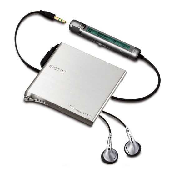
Headphones/earphones with a remote control (1)
Battery charging stand (1)
AC power adaptor (for the supplied battery charging stand) (1)
Headphone adaptor (1)
Carrying pouch (1)
Design and specifications are subject to change without notice.
PORTABLE MINIDISC PLAYER
MZ-E10
US Model
Canadian Model
AEP Model
UK Model
E Model
Tourist Model
NEW
MT-MZE10-184
ABX-1ES
(Unit: Approx. hours) (JEITA
SP Stereo
LP2
LP4
(normal)
Stereo
Stereo
23
33
40
1
7
/
x 2
/
4
8
2)
)
13
x
/
in.)
32
Advertisement
Table of Contents

Related Manuals for Sony MZ-E10


Summary of Contents for Sony MZ-E10
-
Page 1: Specifications
“ Preserving battery power” ). Error correction Measured in accordance with the JEITA (Japan Electronics and ACIRC (Advanced Cross Interleave Reed Solomon Code) Information Technology Industries Association) standard (using a Sony Sampling frequency MDW-series Mini-disc). 44.1 kHz With a fully charged battery. -
Page 2: Table Of Contents
LES DIAGRAMMES SCHÉMATIQUES ET LA LISTE DES PIÈCES SONT CRITIQUES POUR LA SÉCURITÉ DE FONCTIONNEMENT. NE REMPLACER CES COMPOSANTS QUE PAR DES PIÈSES SONY DONT LES NUMÉROS SONT * Replacement of SN761058ZQL (IC501) and LC896442-VH4- DONNÉS DANS CE MANUEL OU DANS LES SUPPÉMENTS PUBLIÉS PAR SONY. -
Page 3: Servicing Note
MZ-E10 SECTION 1 SERVICING NOTE When repairing this device with the power on, if you remove the main board, this device stops working. In this case, you work without the device stopping by fastening the hook of the Open/Close detection switch (S803). -
Page 4: General
MZ-E10 SECTION 2 This section is extracted from GENERAL instruction manual. The Player Playing an MD Insert an MD. 1 Slide OPEN to open the lid. 2 Insert an MD. 3 Close the lid. 1 i (Headphones/earphones) jack 2 GROUP button 3 “3-color info-LED”... -
Page 5: Disassembly
MZ-E10 SECTION 3 DISASSEMBLY The equipment can be removed using the following procedure. Bracket ASSY POWER board, MAIN board Mechsnism deck Panel ASSY (S), upper (MT-MZE10-184) CONTROL board Optical pick-up ASSY (ABX-1ES) Note : Follow the disassembly procedure in the numerical order given. -
Page 6: Bracket Assy
MZ-E10 3-3. BRACKET ASSY 7 Two screws (M1.4) Sheet (blind) 6 Screw (M1.4) 0 Bracket ASSY 9 Switch flexible board (CN801) 2 Plate, retainer 1 Screw (M1.4) 4 Lid (DC), battery case 5 Konb (power) 3-4. POWER BOARD, MAIN BOARD... -
Page 7: Control Board
MZ-E10 3-5. CONTROL BOARD Bracket ASSY 7 CONTROL board 6 Button (control) 4 Cover (control) 5 Switch flexible board (CN801) 2 Remove three claws 3 Knob (open) 1 Screw (M1.4) 3-6. OPTICAL PICK-UP ASSY (ABX-1ES) 3 Screw, tapping 6 Optical pick-up ASSY... -
Page 8: Test Mode
MZ-E10 SECTION 4 TEST MODE 4-1. GENERAL Remote control LCD • When entered in the TEST MODE, this set provides the Overall Adjustment mode which allows CD and MO discs to be auto- matically adjusted. In the Overall Adjustment mode, the system... - Page 9 MZ-E10 4-4. MANUAL MODE 4. During each test mode, the display is changed from one to another each time DISPLAY key is pressed. 4-4-1. Outline of the function The Manual mode is designed to perform adjustments and operational checks on the set’s operation according to each •...
- Page 10 MZ-E10 4-6. KEY CHECK MODE 4-6-1. Outline of the function This mode is used to check to make sure that each of the keys (including the slide switch) on the set operates normally. 4-6-2. Setting the Key Check mode 1. Set the TEST MODE. Press and hold down DISPLAY (for more than 2 sec) to set the Key Check mode.
-
Page 11: Electrical Adjustments
MZ-E10 SECTION 5 ELECTRICAL ADJUSTMENTS 5-1. GENERAL 5-3-2. Changing Adjustment values Adjustment settings are cleared when NV initialize is performed. In this set, CD and MO discs can be automatically adjusted by set- So right after performing NV initialize you must rewrite the correct ting the Overall Adjustment mode within the TEST MODE, data according to the microcomputer version. - Page 12 MZ-E10 12.Press the key. (Address section starts flashing.) 24.Press the key to return to Manual mode. LCD display LCD display 862 88D3 862 VarWrt 01 This section (address) flashes. Data value. 13.Press the key to return to Manual mode. 25.Press the key and write in the correction data.
- Page 13 MZ-E10 Adjustment value:1.05V 3. Press key to write the adjustment value, item No. will Standard value:1.04 to 1.055V change to 743. MAIN BOARD (SIDE A) 5-4-4. VC2 adjustment method 1. Set the overall adjustment mode and set the item No. to 743.
- Page 14 MZ-E10 2. Set the manual mode, item No. will change to 754. Adjustment value:1.75V Standard value:1.75 to 1.80V LCD display MAIN BOARD (SIDE A) 754 ChgV L XX TP909 HOLD C302 3. Connect a digital voltmeter to TP962 on the main board and...
- Page 15 MZ-E10 5-5-5.Current Amplifier (L) adjustment method 4. Adjust with the remote control keys so VOL + VOL – 1. Connect TP953 to TP959 on the main board. that the temperature value is at room temperature. 2. Set the test mode.
- Page 16 MZ-E10 2. Insert CD disc in the set, and press . key to set the Overall 3. Press the key. CD Adjustment mode. LCD display Automatic adjustments are made. 043 Res *** LCD display XXX CD RUN After reset is completed LCD display XXX: Item No.
- Page 17 MZ-E10 . Overall MO adjustment items 5. Press the key and set the adjustment setting to 01. VOL + Item No. Contents LCD display ALFA offset adjustment 023 Patch 01 IJ offset adjustment FE offset adjustment 6. Press the key.
- Page 18 MZ-E10 Varsion 1.000 Address Data Address Data 8921 8962 8922 8963 8923 8964 8924 8965 8925 8966 8926 8967 8928 8968 8929 8969 892A 896A 892B 896B 892C 896C 892D 896D 892E 896E 8931 8971 8932 8972 8933 8973 8934...
-
Page 19: Diagrams
MZ-E10 SECTION 6 DIAGRAMS 6-1. BLOCK DIAGRAMS IC301 HEADPHONE AMP (D CLASS AMP) IC501 Q303 RF AMP,FOCUS/TRACKING ERROR AMP OUT1 D LPWM+ L-CH VREF EFMO A-GND VREF10 OUT2 RF OUT D RPWM+ R-CH J301 EFMIN VCC-1 D-GND PEAK Q102,202 PEAK... -
Page 20: Printed Wiring Boards - Main Section (1/2)
MZ-E10 : Uses unleaded solder. 6-2. PRINTED WIRING BOARDS – MAIN SECTION (1/2) – See page 25 for Notes. CN801 Semiconductor C804 Location CONTROL BOARD (SIDE A) HOLD C302 Ref. No. Location TP909 S804 (CLASS-D) CONTROL BOARD (SIDE B) HOLD... -
Page 21: Printed Wiring Boards - Main Section (2/2)
MZ-E10 : Uses unleaded solder. See page 25 for Notes. 6-3. PRINTED WIRING BOARDS – MAIN SECTION (2/2) – MAIN BOARD (SIDE B) 1-686-492- (11) -
Page 22: Schematic Diagram - Main Section (1/3)
MZ-E10 6-4. SCHEMATIzC DIAGRAM – MAIN SECTION (1/3) – See page 25 for Notes. See page 26 for IC Pin Function Description. -
Page 23: Schematic Diagram - Main Section (2/3)
MZ-E10 6-5. SCHEMATIzC DIAGRAM – MAIN SECTION (2/3) – See page 25 for Notes. -
Page 24: Schematic Diagram - Main Section (3/3)
MZ-E10 6-6. SCHEMATIzC DIAGRAM – MAIN SECTION (3/3) – See page 25 for Notes. - Page 25 MZ-E10 WAVEFORMS Note on Printed Wiring Boards • X : parts extracted from the component side. • : Through hole. • : Pattern from the side which enables seeing. (The other layers' patterns are not indicated.) Caution: 1.3 Vp-p Pattern face side:...
-
Page 26: Ic Pin Function Descrintion
MZ-E10 6-7. IC PIN FUNCTION DESCRINTION • IC601 LC-896442-VH4-16-E (DIGITAL SIGNAL PROCESSOR, DIGITAL SERVO SIGNAL PROCESSOR, EFM/ACIRC ENCODER/DECODER, SHOCK PROOF MEMORY CONTROLLER, 16M BIT D-RAM, SYSTEM CONTROL) (MAIN BOARD) Pin No. Pin Name Description MWEB – Not used (open) XD_MUTE... - Page 27 MZ-E10 Pin No. Pin Name Description XSLP MTR OP Start/stop signal output to motor drive (CXA8125ER-TBM-E) XDISC DET Not used (connected to ground) D_EN2 Drive control signal output to Headphone AMP (NJU-8713V-TE2) 53 to 56 SMON 0 to 3 –...
- Page 28 MZ-E10 Pin No. Pin Name Description D LPWM+ L-CH audio signal output D PWM– Not used (open) D RPWM+ R-CH audio signal output D RPWM– Not used (open) D CPWM Not used (open) DPVDD – Power supply VVDD – Power supply...
- Page 29 MZ-E10 Pin No. Pin Name Description VCC2 – Power supply MAD4 – Not used 175 to 180 ADR11 to 16 – Not used – Ground ADR17 – Not used – Not used (open) DEFECT – Not used (open) DECLK –...
-
Page 30: Ic Block Diagrams
MZ-E10 6-8. IC BLOCK DIAGRAMS IC951 SC901582EPR2 NSW4 VREF TIME CAP_C_LIM DIVIDER VI2DET NSW3 LOGIC SIGNAL I_CTL1 RECEIVER NSW1 LOGIC I_SEL SIGNAL I_CTL2 RECEIVER AD_SEL WK_DET VREF PWR_WAKE DELAY VREF BATT VOLTAGE REFERENCE IC901 SC901580EPR2 (HP AMP) AMP1 CONTROL BANDGAP... - Page 31 MZ-E10 IC301 NJU8713V-TE2 BEEP VSS 0 VSS 0 OUT 1 OUT 2 VDD 0 VDD 0 BPZ OUTPUT IC551 CXA8125ER-TBM-E LOGIC PRE DRIVE SPPD 36 SPGND SPMAX 35 SPVS IN2F 34 SPCIN PHASE COMP. IN2R 33 SPIL WAVE REG. 32 SPVCO PHASE COMP.
- Page 32 MZ-E10 IC501 SN761058ZQL AVCC PEAK/ OFTRK T-ON BOTM 42 FE ABCD 41 ABCD 40 RFI A GND 39 ASSY OFC-C1 38 CIG TPP/WPP OFC-C2 37 EFMO VREF10 DGND RESET 34 VGIN VREF09 33 SBUS AVCC2 AVCC2 32 SCK PD-NI CPOUT...
-
Page 33: Exploded Views
MZ-E10 SECTION 7 EXPLODED VIEWS NOTE : • -XX, -X mean standardized parts, so they • The mechanical parts with no reference The components identified by may have some difference from the original number in the exploded views are not mark 0 or dotted line with mark one. -
Page 34: Mechanism Deck Section (Mt-Mze10-184)
MZ-E10 7-2. MECHANISM DECK SECTION (MT-MZE10-184) M902 supplied supplied M901 The components identified by mark 0 or dotted line with mark 0 are critical for safety. Replace only with part number specified. Les composants identifiés par une marque 0 sont critiques pour la sécurité. -
Page 35: Electrical Parts List
MZ-E10 SECTION 8 ELECTRICAL PARTS LIST MAIN NOTE : • Due to standardization, replacements in the • SEMICONDUCTORS The components identified by mark 0 parts list may be different from the parts In each case, u : µ , for example :... - Page 36 MZ-E10 MAIN Ref. No. Part No. Description Remark Ref. No. Part No. Description Remark C902 1-135-837-91 TANTAL. CHIP 22uF 6.3V FB803 1-469-082-21 FERRITE C903 1-135-837-91 TANTAL. CHIP 22uF 6.3V C904 1-164-935-11 CERAMIC CHIP 470PF < IC > C905 1-164-943-11 CERAMIC CHIP 0.01uF...
- Page 37 MZ-E10 MAIN POWER CONTROL Ref. No. Part No. Description Remark Ref. No. Part No. Description Remark R310 1-218-990-11 SHORT CHIP R903 1-208-707-11 METAL CHIP 0.5% 1/16W R311 1-218-953-11 RES-CHIP 1/16W R904 1-218-981-11 RES-CHIP 220K 1/16W R312 1-218-969-11 RES-CHIP 1/16W R905...
- Page 38 MZ-E10 CONTROL Ref. No. Part No. Description Remark R814 1-218-961-11 RES-CHIP 4.7K 1/16W R815 1-218-965-11 RES-CHIP 1/16W R816 1-218-965-11 RES-CHIP 1/16W < SWITCH > S801 1-786-401-21 SWITCH, TACTILE (., > N, x, VOL–, VOL+) ****************************************************** MISCELLANEOUS ************* 1-686-493-11 PWB, SWITCH FLEXIBLE...
- Page 39 MZ-E10 MEMO...
- Page 40 MZ-E10 REVISION HISTORY Clicking the version allows you to jump to the revised page. Also, clicking the version at the upper right on the revised page allows you to jump to the next revised page. Ver. Date Description of Revision...