
Related Manuals for Meyer Sound MILO 120


Summary of Contents for Meyer Sound MILO 120
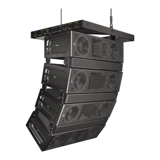
- Page 1 M SERIES OPERATING INSTRUCTIONS MILO 120 High-Power Expanded Coverage Curvilinear Array Loudspeaker Keep these important operating instructions. Check www.meyersound.com for updates.
- Page 2 MILO, TruPower, RMS and REM are trademarks of Meyer Sound. Meyer Sound, Meyer Sound MAPP Online, SIM and QuickFly are registered trademarks of Meyer Sound Laboratories Inc. (Reg. U.S. Pat. & Tm. Off.). All third-party trademarks mentioned herein are the property of their respective trademark holders.
-
Page 3: Important Safety Instructions
2. Keep these instructions. 12. Use only with the caster rails or rigging specified by 3. Heed all warnings. Meyer Sound, or sold with the loudspeaker. Handles 4. Follow all instructions. are for carrying only. 5. Do not use this loudspeaker near water. -
Page 4: Safety Summary
Vuelva a conectar la alimentacion without using weather protection par du personnel qualifié et agréé de voltaje una vez efectuadas equipment from Meyer Sound. par le constructeur. todas las interconexiones de Do not allow water or any señalizacion de audio. -
Page 5: Table Of Contents
How Line Arrays Work MILO 120 Curvilinear Array High Frequencies Mid to Low Frequencies Adjusting Line Array Coverage Using MILO 120 As Downfill for MILO Curvilinear Arrays High-Frequency Design Strategies Low-Frequency Design Strategies Electronically Driving the Array High-Frequency Equalization Strategies... - Page 6 Applications CHAPTER 7: QuickFly Rigging ® MILO 120 Custom AlignaLinks MILO 120 As Downfill in MILO/MILO 120 Curvilinear Arrays MG-3D/M Multipurpose Grid MCF-MILO Caster Frame APPENDIX A: Amplifier Replacement and Optional Rain Hood Using the Rain Hood (Weather-Protected Loudspeakers) Removing the HP-4/MILO 120 Amplifier Replacing the HP-4/MILO 120 Amplifier...
-
Page 7: Introduction
Chapter 3: Amplification and Audio will help you under- offers a helpful tip relevant to the topic stand and harness the power of the MILO 120 amplifier and at hand. audio systems. Amplifier specifications, connectivity, limit- ing and cooling system components are all covered. - Page 8 INTRODUCTION...
-
Page 9: Chapter 1: Introducing The Milo 120 Loudspeaker
MILO or M3D line array loudspeaker systems. The weather-protected version of MILO 120 includes MILO 120 can also be used to form wide coverage arrays or comprehensive weather protection to suit frequent use in in other fill applications that can be satisfied by one or two inclement outdoor applications as well as permanent instal- cabinets. -
Page 10: Rigging And Transport
European and US truck widths, while its AlignaLinks are fully compatible with the optional MCF- MILO caster frame — allowing you to transport stacks of MILO 120, with or without the MILO 120-I insert, and facili- tating the use of forklifts. NOTE:... -
Page 11: Integrated Amplifier And Processing
MILO 120’s mid-high section (560 Hz to 4.2 kHz) uses a long-term power compression to less than 1 dB (versus the single 1.5-inch exit, 4-inch diaphragm compression driver typical 3 to 6 dB for conventional systems). - Page 12 CHAPTER 1...
-
Page 13: Chapter 2: Power Requirements
120 V AC from line to ground in the above ex- 120 loudspeaker. ample). AC POWER MILO 120 uses a NEMA L6-20P, an IEC 309 male power When AC power is applied to the MILO 120 loudspeaker, connector or a multi-pin VEAM connector and complies with worldwide product safety standards. -
Page 14: Current Requirements
16 A pk 37 A pk term peak If MILO 120 shuts down due to either low or high voltage, its power supply automatically turns on again after three seconds if the voltage has returned to either normal oper- NOTE: For best performance, the AC cable ating window. -
Page 15: Power Connector Wiring Conventions
VEAM multi-pin connector power pin-out Figure 2.4. �������������� If your MILO 120 loudspeaker is fitted with the VEAM multi- pin connector, see the Meyer Sound document VEAM Cable Wiring Reference (part number 06.033.113) for the wiring conventions and pin-outs for AC, audio, and RMS connec- tions. -
Page 16: Electrical Safety Issues
TIP: Use the ring located on the rear of MILO 120’s cabinet (to the right of the ampli- fier) to provide strain relief for power and signal cables. Do not use this ring for any other purpose. -
Page 17: Chapter 3: Amplification And Audio
The input impedance grounding schemes are not recommended. for a single MILO/MILO 120 loudspeaker is 10 kOhms: if n represents the number of MILO/MILO 120 loudspeakers in an array, paralleling the inputs of n MILO/MILO 120 loud-... -
Page 18: Amplification And Protection Circuitry
Figure 3.2 shows how MILO 120’s drivers are A ring/stud fitting is provided on the rear of the MILO 120 connected to the amplifier. loudspeaker to act as a strain relief for cabling. Using this fitting will minimize the chance of cables being damaged... -
Page 19: The Trupower® Limiting System
CHAPTER 3 To utilize the strain relief fitting, insert the signal, data, and The actual power is monitored for three of MILO 120’s four AC connections into each loudspeaker as the array is being amplifier channels. When the safe continuous power level rigged (swag all cables under the optional rain hood’s side... -
Page 20: Very-High Frequency Limiters
Very-High Frequency Limiters FANS AND COOLING SYSTEM The two 2-inch diaphragm very-high frequency compres- MILO 120 uses a forced-air cooling system with four fans sion drivers are powered by the fourth amplifier channel. to prevent the amplifier modules from overheating. The fans... - Page 21 NOTE: In the highly unlikely event that the secondary fans do not keep the temperature below 85˚ C, the MILO 120 loudspeaker automati- cally shuts down until AC power is removed and reapplied. If the MILO 120 loudspeaker shuts down again after cooling and reapplying AC power, con- tact Meyer Sound for repair information.
- Page 22 CHAPTER 3...
-
Page 23: Chapter 4: Rms Remote Monitoring System
Sound self-powered loudspeakers with a Windows-based communication board and in the computer RMS database PC at the sound mix position or other location. MILO 120 is unless you modify it. Loudspeaker View labels can be modi- RMS-ready and fitted standard with an RMS communica- fied at any time, allowing you to customize how you view... -
Page 24: Service Led (Red)
When used in combination with the Service But- ton, the card will be decommissioned from the network and the red Service LED will blink. Figure 4.4: Sample RMS display panel showing MILO, MILO 120 and M3D-Sub loudspeakers. Activity LED (Green) -
Page 25: Chapter 5: Line Arrays And System Integration
The MILO 120 loudspeaker employs a unique combination of drivers to enable you to optimize both coverage and di- rectivity in a MILO 120 line array system. To achieve optimal NOTE: Due to the larger splay angles, the results, it’s important to understand how these components... -
Page 26: Mid To Low Frequencies
MILO/MILO 120 array, the design will be depen- dent on three factors: Regardless of the needs of your system design, fine-tuning coverage for a MILO 120 curvilinear array will be dependent ■ Number of Array Elements. Determining the number on three factors:... -
Page 27: High-Frequency Design Strategies
MILO are used to cover lon- more elements in the array, the more directional the array ger distances, while greater angles for MILO 120 are used in becomes, providing more SPL in this range. The directional... -
Page 28: Line Driver
IN CH 1 Post Array (4) 700-HP SUB (4) 700-HP SUB IN CH 2 Post Array IN CH 3 Post HPF Digital Delay Digital Delay/EQ 2 In x 6 Out Sample block diagram of MILO, MILO 120, 700-HP system Figure 5.2. -
Page 29: Using Milo/Milo 120 With Subwoofers
Using the LD-3’s filters helps to easily integrate and opti- pensates for the air absorption of the air at high fre- mize your MILO/MILO 120 arrays with subwoofers. The use quencies. Each section allows different correction set- of high-pass filters augment array headroom by removing tings according to the distance each section’s intended... -
Page 30: Milo/Milo 120 And The 700-Hp Subwoofer
In applications where M3D-Sub features like directional low- ity to be vertically arrayed with MILO/MILO 120 since they frequency control are not needed, a MILO/MILO 120 array share the same width. -
Page 31: Digital Signal Processors
(DSP) are optional and should be used very carefully due to phase shifts that can cause cancellations. If DSP is used, both MILO 120 loudspeakers and subwoof- ers should be fed from the same DSP in order to keep their delay time the same. - Page 32 CHAPTER 5...
-
Page 33: Chapter 6: System Design And Integration Tools
CHAPTER 6 CHAPTER 6: SYSTEM DESIGN AND INTEGRATION TOOLS Meyer Sound offers two comprehensive tools to assist you As its name indicates, MAPP Online is an online applica- with the acoustical and functional requirements of system tion: when a prediction is requested, data is sent over the design and optimization. -
Page 34: Sim Measurement System
■ Optimizing subwoofer integration Source Independent Measurement Technique ■ Optimizing loudspeaker arrays The SIM audio analyzer implements the Meyer Sound SIM can also be used in the following applications: source independent measurement technique, a dual-chan- nel method that accommodates statistically unpredictable ■... -
Page 35: Chapter 7: Quickfly Rigging
QuickFly attach to the MILO standard rigging frame. facilitates flying or ground stacking MILO 120 loudspeakers When setting the angles for the MILO 120, use the in a variety of applications. numbers engraved on the rear AlignaLinks as a guide, and ignore the numbers engraved on the frame. -
Page 36: Milo 120 As Downfill In Milo/Milo 120 Curvilinear Arrays
Front hole not used 13 (optimal for most applications) and 15 degrees of splay between the last MILO standard and the top-most MILO 120 cabinet in the array. Use the MILO 120 custom Top (rigging) AlignaLinks between the two cabinets to achieve these position angles. -
Page 37: Mg-3D/M Multipurpose Grid
MILO/MILO 120 loudspeakers and/or M3D transport stacks of up to four MILO/MILO 120 cabinets, us- line array loudspeakers (or M3D-Subs) in numerous configu- ing the MILO 120 AlignaLinks to secure the cabinets to the rations (Figure 7.6). caster frame. - Page 38 Figure 7.10. Configuration for transporting cabinets on the MCF-MILO caster frame leaving the MILO 120-I; in this case, there is a splay of 4 degrees between the last cabinet and the caster frame.
-
Page 39: Appendix A: Amplifier Replacement And Optional Rain Hood
(Figure A.4). �� �� Figure A.2: A fully opened rain hood installed on a MILO 120 �� CAUTION: When operating a weather-pro- ����... -
Page 40: Replacing The Hp-4/Milo 120 Amplifier
REMOVING THE HP-4/MILO 120 AMPLIFIER (WITH RAIN HOOD) 4. Carefully install the fabric rain hood, using the stainless If you need to remove and replace the HP-4/MILO 120 am- steel screws and washers. plifier from a weather-protected MILO 120 loudspeaker, first remove the rain hood, then remove the amplifier follow-... -
Page 41: Appendix B: Milo 120 Specifications
APPENDIX B APPENDIX B: MILO 120 SPECIFICATIONS ACOUSTICAL Note: The low-frequency power response of the system will increase according to the length of the array. Operating frequency range 60 Hz - 18 kHz Note: Recommended maximum operating frequency range. Response depends upon loading conditions and room acoustics. - Page 42 APPENDIX B AUDIO INPUT Type Differential, electronically balanced Max. common mode range ±15 V DC, clamped to earth for voltage transient protection Connectors Female XLR input with male XLR loop output or VEAM Input impedance 10 kΩ differential between pins 2 and 3 Wiring Pin 1: Chassis/earth through 220 kΩ, 1000 pF, 15 V clamp network to provide virtual ground lift at audio frequencies...
- Page 43 Black textured Protective grille Powder-coated hex stamped steel Rigging QuickFly MRF-MILO rigging frame, MILO 120 AlignaLink connectors and 3/8” x 1.125” quick release pins Dimensions 54.00” w x 14.47” h x 22.00” d (1372 mm x 368 mm x 559 mm) Weight 235 lbs (106.60 kg)
- Page 44 APPENDIX B...
- Page 48 Meyer Sound Laboratories Inc. 2832 San Pablo Avenue Berkeley, CA 94702 www.meyersound.com © 2004 T: +1 510 486.1166 Meyer Sound Laboratories Inc. F: +1 510 486.8356 05.142.003.01 A...