Table of Contents
Advertisement
Quick Links
Advertisement
Table of Contents

Related Manuals for Planet WNAP-6300


Summary of Contents for Planet WNAP-6300
- Page 1 802.11n Outdoor Wireless CPE AP/Router WNAP-6300 User’s Manual Version 1.0...
- Page 2 Copyright Copyright© 2011 by PLANET Technology Corp. All rights reserved. No part of this publication may be reproduced, transmitted, transcribed, stored in a retrieval system, or translated into any language or computer language, in any form or by any means, electronic, mechanical, magnetic, optical, chemical, manual or otherwise, without the prior written permission of PLANET.
- Page 3 inches) during normal operation. The availability of some specific channels and/or operational frequency bands are country dependent and are firmware programmed at the factory to match the intended destination. The firmware setting is not accessible by the end user. CE Mark Warning This is a Class B product.
- Page 4 Do not dispose of WEEE as unsorted municipal waste and have to collect such WEEE se parately. Revision User’s Manual for PLANET IEEE802.11b/g/n Wireless LAN Outdoor CPE AP/Router Model: WNAP-6300 Rev: 1.0 (December, 2010)
-
Page 5: About This Manual
About This Manual This user manual is intended to guide professional installer to install the IEEE WNAP-6300 (the WNAP-6300) and how to build the infrastructure centered on it. It includes procedures to assist you in avoiding unforeseen problems. Conventions For your attention on important parts, special characters and patterns are used in this manual: Note: This indicates an important note that you must pay attention to. -
Page 6: Table Of Contents
Content Chapter 1 Introduction......................... 1 1.1 Introduction........................... 1 1.2 Appearance ..........................2 1.3 Key Features ..........................2 1.4 Typical Application ........................3 Chapter 2 Hardware Installation ......................4 2.1 Preparation before Installation...................... 4 Professional Installation Required ....................4 Safety Precautions.......................... 4 Installation Precautions........................ - Page 7 5.6 Reboot ............................44 5.7 System Log..........................45 5.8 Ping Watch Dog.......................... 46 Chapter 6 Status..........................47 6.1 View WNAP-6300 Basic Information..................47 6.2 View Association List ........................48 6.3 View Network Flow Statistics...................... 49 6.4 View Bridge Table........................50 6.5 View ARP Table ..........................
- Page 8 Figure 10 Pole Mounting – Step 3......................11 Figure 11 Move the Rubber........................12 Figure 12 Login Page........................... 15 Figure 13 Main Page of WNAP-6300....................16 Figure 14 Basic System Settings ......................17 Figure 17 RADIUS Settings ......................... 20 Figure 15 Basic Wireless Settings ....................... 28 Figure 16 Site Survey...........................
- Page 9 TABLE Table 1 WNAP-6300 Factory Default Settings ..................13 Table 2 ACSII ............................53 Table 3 Public Software Name and Description................... 55...
-
Page 10: Chapter 1 Introduction
As an 802.11b/g compliant wireless device, the WNAP-6300 is able to give stable and efficient wireless performance, while designed with IEEE 802.11n standard and high output power makes it possible to deliver several times faster data rate than normal wireless device and higher bandwidth with longer range for outdoor applications. -
Page 11: Appearance
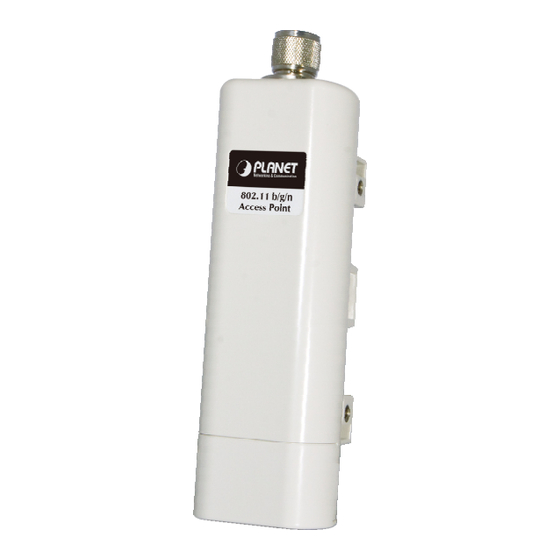
1.2 Appearance Figure 1 WNAP-6300 Outlook 1.3 Key Features Compliant with IEEE 802.11b/g and IEEE 802.11n as well Support Power Through Ethernet which is supplied with 12VDC. High reliable watertight housing endures almost any harsh environments Four operating modes including AP, Wireless Client, WDS and AP+WDS Support 64/128/152-bit WEP and 802.1X, WPA, WPA2, WPA&WPA2,WPA-PSK, WPA2-PSK, and... -
Page 12: Typical Application
1.4 Typical Application This section describes the typical applications of WNAP-6300. By default, it is set to AP mode which allows it to establish a wireless coverage; besides, it is also able to join any available wireless network under wireless client mode. The WNAP-6300 is able to deliver stable and efficient broadband connectivity for various applications. -
Page 13: Chapter 2 Hardware Installation
To keep you safe and install the hardware properly, please read and follow these safety precautions. If you are installing WNAP-6300 for the first time, for your safety as well as others’, please seek assistance from a professional installer who has received safety training on the hazards involved. -
Page 14: Installation Precautions
EMD (Lightning) DAMAGE IS NOT COVERED UNDER WARRNTY. Users MUST use the “Power cord & PoE Injector” shipped in the box with the WNAP-6300. Use of other options will cause damage to the WNAP-6300. Users MUST power off the WNAP-6300 first before connecting the external antenna to it. Do not switch from built-in antenna to the external antenna from WEB management without physically attaching the external antenna onto the WNAP-6300;... - Page 15 Pole Mounting Ring Power Adapter & PoE Injector Warning: Users MUST use the “Power Adapter & PoE Injector” shipped in the box with WNAP-6300. Use of other options will cause damage to the WNAP-6300. Chapter 2 Hardware Installation Page 6...
-
Page 16: Hardware Installation
2.2 Hardware Installation Physical Connection The bottom of the WNAP-6300 is the movable cover. Grab the cover by pressing the push bolt and pull it out as the figure shown below. Figure 3 Move the Cover align the rail Plug a standard Ethernet cable into the RJ45 port. (Cat5/5e with 8-wire required) -
Page 17: Figure 5 Seal The Bottom
Slide the cover back to seal the bottom of the WNAP-6300. Figure 5 Seal the Bottom Plug the power cord into the DC port of the PoE injector as the following right picture shows. Figure 6 Connect to PoE Injector... -
Page 18: Figure 7 Complete Set
Figure 7 Complete Set Note: Be reminded, the UTP wire distance toward your WNAP-6300 to the Ethernet devices, such as Ethernet Switch, is 100 meters, this passive POE injector can be in any point of this 100 meters UTP distance where there is a shell or protected location for this POE injector. -
Page 19: Pole Mounting
Pole Mounting Turn the WNAP-6300 over. Put the pole mounting ring through the middle hole of it. Note that you should unlock the pole mounting ring with a screw driver before putting it through WNAP-6300 as the following right picture shows. -
Page 20: Figure 10 Pole Mounting – Step 3
Now you have completed the hardware installation of WNAP-6300. Figure 10 Pole Mounting – Step 3 Chapter 2 Hardware Installation Page 11... -
Page 21: Using The External Antenna
If you prefer to use the external antenna with N-type connector for your application instead of the built-in directional antenna, please follow the steps below. Grab the black rubber on the top of WNAP-6300, and slightly pull it up. The metal N-type connector will appear. -
Page 22: Chapter 3 Basic Settings
Chapter 3 Basic Settings 3.1 Factory Default Settings We’ll elaborate the WNAP-6300 factory default settings. You can re-acquire these parameters by default. If necessary, please refer to the “Restore Factory Default Settings”. Table 1 WNAP-6300 Factory Default Settings Features Factory Default Settings... -
Page 23: System Requirements
3.3 How to Login the Web-based Interface The WNAP-6300 provides you with user-friendly Web-based management tool. Open Web browser and enter the IP address (Default: 192.168.1.1) of WNAP-6300 into the address field. You will see the login page as below. -
Page 24: Figure 12 Login
Figure 12 Login Page Enter the username (Default: admin) and password (Default: admin) respectively and click “Login”. As you can see, this management interface provides five main options in the black bar above, which are Status, System, Wireless, Management and Tools. Chapter 3 Basic Settings Page 15... -
Page 25: Figure 13 Main Page Of Wnap-6300
Figure 13 Main Page of WNAP-6300 Note: The username and password are case-sensitive, and the password should be no more than 19 characters! Chapter 3 Basic Settings Page 16... -
Page 26: Basic System Settings
3.4 Basic System Settings For users who use the WNAP-6300 for the first time, it is recommended that you begin configuration from “Basic Settings” in “System” shown below: Figure 14 Basic System Settings Basic Settings Network Mode: Specify the network mode, including Bridge and Router. It is easy to configure parameters in Bridge Mode;... - Page 27 WNAP-6300 is able to obtain IP settings automatically from that DHCP server. Note: When the IP address of the WNAP-6300 is changed, the clients on the network often need to wait for a while or even reboot before they can access the new IP address. For an immediate access to the bridge, please flush the netbios cache on the client computer by running the “nbtstat...
- Page 28 LAN Settings: When DHCP Server is disabled, users can specify IP address and subnet mask for WNAP-6300 manually. Make sure the specified IP address is unique on your network in order to prevent IP conflict. When DHCP Server is enabled, users may specify DHCP IP Address Range, DHCP Subnet Mask, DHCP Gateway and Lease Time (15-44640 minutes).
-
Page 29: Radius Settings
Bridge mode and AP + Bridge mode are similar to AP mode when device is set to Router mode; WAN is on wired port and LAN is on wireless port. Thus users must also connect. WNAP-6300 with another wireless device before it is set to Router mode and access WNAP-6300 via the connected wireless device. -
Page 30: Time Settings
3.6 Time Settings Compliant with NTP, the WNAP-6300 is capable of keeping its time in complete accord with the Internet time. Make configuration in “Time Settings” from “System”. To use this feature, check “Enable NTP Client Update” in advance. -
Page 31: Firewall Settings
Source IP Filtering: The source IP filtering gives users the ability to restrict certain types of data packets from your local network to Internet through WNAP-6300. Use of such filters can be helpful in securing or restricting your local network. - Page 32 Destination IP Filtering: The destination IP filtering gives you the ability to restrict the computers in LAN from accessing certain websites in WAN according to specified IP addresses. Check the “Enable Source IP Filtering” checkbox and enter the IP address of the clients to be restricted. Hit Apply to make the setting take effect.
- Page 33 Source Port Filtering: The source port filtering enable you to restrict certain ports of data packets from your local network to Internet through WNAP-6300. Use of such filters can be helpful in securing or restricting your local network. Figure 21 Source Port Filtering...
- Page 34 Destination Port Filtering: The destination port filtering enables you to restrict certain ports of data packets from your local network to Internet through WNAP-6300. Use of such filters can be helpful in securing or restricting your local network. Figure 22 Destination Port Filtering...
- Page 35 Port Forwarding: The port forwarding allows you to automatically redirect common network services to a specific machine behind the NAT firewall. These settings ne are only necessary if you wish to host some sort of server like a web server or mail server on the private local network behind WNAP-6300’s NAT firewall.
- Page 36 Figure 24 DMZ Chapter 3 Basic Settings Page 27...
-
Page 37: Basic Wireless Settings
Wireless Mode Four operating modes are available on WNAP-6300. Wireless Client: The WNAP-6300 is able to connect to the AP and thus join the wireless network around it. AP: The WNAP-6300 establishes a wireless coverage and receives connectivity from other wireless devices. - Page 38 Usually “Full” is preferred. Data Rate Usually “Auto” is preferred. Under this rate, the WNAP-6300 will automatically select the highest available rate to transmit. In some cases, however, like where there is no great demand for speed, you can have a relatively-low transmit rate for compromise of a long distance.
- Page 39 Channel Mode Four levels are available: 5MHz, 10MHz, 20MHz and 40MHz. The last one can enhance data throughput, but it takes more bandwidth, thus it might cause potential interference. Extension Channel Protection Mode This is to avoid conflict with other wireless network and boost the ability of your device to catch all 802.11g transmissions.
-
Page 40: Site Survey
3.9 Site Survey Under wireless client mode, the WNAP-6300 is able to perform site survey, through which, information on the available access points will be detected. Open “Basic Settings” in “Wireless”, by clicking the “Site Survey” button beside “Wireless Mode”... -
Page 41: Chapter 4 Advanced Settings
Chapter 4 Advanced Settings 4.1 Advanced Wireless Settings Open “Advanced Settings” in “Wireless” to make advanced wireless settings. Figure 17 Advanced Wireless Settings WMM Support WMM (Wi-Fi Multimedia) is a subset of 802.11e. It allows wireless communication to define a priority limit on the basis of data type under AP mode only, thus those time-sensitive data, like video/audio data, may own a higher priority than common one. - Page 42 Under 802.11n mode, enable it to obtain better data rate if there is no negative compatibility issue. RTS Threshold The WNAP-6300 sends RTS (Request to Send) frames to certain receiving station and negotiates the sending of a data frame. After receiving an RTS, that STA responds with a CTS (Clear to Send) frame to acknowledge the right to start transmission.
- Page 43 Available only under AP mode, it defines the maximum amount of wireless clients allowed to be connected. Space in Meter/ACK Timeout To decrease the chances of data retransmission at long distance, the WNAP-6300 can automatically adjust proper ACK timeout value by specifying distance of the two nodes. Flow Control It allows the administrator to specify the incoming and outgoing traffic limit by checking “Enable...
-
Page 44: Wireless Security Settings
4.2 Wireless Security Settings To prevent unauthorized radios from accessing data transmitting over the connectivity, the WNAP-6300 provides you with rock solid security settings. Security Settings Open “Security Settings” in “Wireless” as below: Figure 18 Security Settings Network Authentication Open System: It allows any device to join the network without performing any security check. - Page 45 TKIP + AES: It allows for backwards compatibility with devices using TKIP. Note: We strongly recommend you enable wireless security on your network! Only setting the same Authentication, Data Encryption and Key in the WNAP-6300 and other associated wireless devices, can the communication be established! Chapter 4 Advanced Settings...
-
Page 46: Access Control
Access Control The Access Control appoints the authority to wireless client on accessing WNAP-6300, thus a further security mechanism is provided. This function is available only under AP mode. Open “Access Control” in “Wireless” as below. Figure 19 Access Control Access Control Mode If you select “Allow Listed”, only those clients whose wireless MAC addresses are in the access... -
Page 47: Wds Settings
WDS Settings Extend the range of your network without having to use cables to link the Access Points by using the Wireless Distribution System (WDS): Simply put, you can link the Access Points wirelessly. Open “WDS Settings” in “Wireless” as below: Figure 30 WDS Settings Enter the MAC address of another AP you wirelessly want to connect to into the appropriate field and click “Apply”... -
Page 48: Chapter 5 Management
Check this box to enable SNMP settings. Protocol Version Select the SNMP version, and keep it identical on the WNAP-6300 and the SNMP manager. Server Port Change the server port for a service if needed; however you have to use the same port to use that service for remote management. -
Page 49: Configure Snmpv3 User Profile
By default, it is set to public and allows all requests. Set Community Specify the password for the incoming Set requests from the management station. By default, it is set to private. Trap Destination Specify the IP address of the station to send the SNMP traps to. Trap Community Specify the password sent with each trap to the manager. -
Page 50: Password
User Name Specify a user name for the SNMPv3 administrator or user. Only the SNMP commands carrying this user name are allowed to access the WNAP-6300. Password Specify a password for the SNMPv3 administrator or user. Only the SNMP commands carrying this password are allowed to access the WNAP-6300. -
Page 51: Upgrade Firmware
The password is case-sensitive and its length can not be exceeding 19 characters! 5.3 Upgrade Firmware Open “Firmware Upload” in “Management” and follow the steps below to upgrade firmware locally or remotely through WNAP-6300’s Web: Figure 34 Upgrade Firmware Chapter 5 Management... -
Page 52: Backup/ Retrieve Settings
Click “Browse” to select the firmware file you would like to load; Click “Upload” to start the upload process; Wait a moment, the system will reboot after successful upgrade. Note: Do NOT cut the power off during upgrade, otherwise the system may crash! 5.4 Backup/ Retrieve Settings It is strongly recommended you back up configuration information in case of something unexpected. -
Page 53: Restore Factory Default Settings
Restore factory default settings via Reset Button If software in WNAP-6300 is unexpectedly crashed and no longer reset the unit via Web, you may do hardware reset via the reset button. Press and hold the button for at least 5 seconds and then release it until the PWR LED gives a blink. -
Page 54: System Log
Figure 37 Reboot 5.7 System Log System log is used for recording events occurred on the WNAP-6300, including station connection, disconnection, system reboot and etc. Open “System Log” in “Tools” as below. Figure 38 System Log Chapter 5 Management Page 45... -
Page 55: Ping Watch Dog
IP Address to Ping: Specify the IP address of the remote unit to ping. Ping Interval: Specify the interval time to ping the remote unit. Startup Delay: Specify the startup delay time to prevent reboot before the WNAP-6300 is fully initialized. -
Page 56: Chapter 6 Status
Chapter 6 Status 6.1 View WNAP-6300 Basic Information Open “Information” in “Status” to check the basic information of WNAP-6300, which is read only. Click “Refresh” at the bottom to have the real-time information. Figure 21 Basic Information Chapter 6 Status... -
Page 57: View Association List
6.2 View Association List Open “Association List” in “Connection” from “Status” to check the information of associated wireless clients. All is read only. Click “Refresh” at the bottom to view the current association list. Figure 22 Connection Chapter 6 Status Page 48... -
Page 58: View Network Flow Statistics
6.3 View Network Flow Statistics Open “Network Flow” in “Status” to check the data packets received on and transmitted from the wireless and Ethernet ports. Click “Refresh” to view current statistics. Figure 23 Network Flow Statistics Poll Interval Specify the refresh time interval in the box beside “Poll Interval” and click “Set Interval” to save settings. -
Page 59: View Bridge Table
6.4 View Bridge Table Open “Bridge Table” in “Status” as below. Click “Refresh” to view current connected status.. Figure 42 Bridge Table 6.5 View ARP Table Open “ARP Table” in “Status” as below. Click “Refresh” to view current table. Figure 43 ARP Table Chapter 6 Status Page 50... -
Page 60: View Active Dhcp Client Table
6.6 View Active DHCP Client Table Open “DHCP Client List” in “Status” as below to check the assigned IP address, MAC address and time expired for each DHCP leased client. Click “Refresh” to view current table. Figure 44 DHCP Client Table Chapter 6 Status Page 51... -
Page 61: Chapter 7 Troubleshooting
• Since the WNAP-6300 comes with a built-in directional antenna, it is recommended make the WNAP-6300 face to the direction where the AP is to get the best connection quality. • In addition, you can start “Site Survey” in “Wireless Basic Settings” to check the signal strength. -
Page 62: Appendix A. Ascii
Appendix A. ASCII WEP can be configured with a 64-bit, 128-bit or 152-bit Shared Key (hexadecimal number or ACSII). As defined, hexadecimal number is represented by 0-9, A-F or a-f; ACSII is represented by 0-9, A-F, a-f or punctuation. Each one consists of two-digit hexadecimal. Table 2 ACSII ASCII ASCII... -
Page 63: Appendix B. Gpl Declamation
Appendix B. GPL Declamation PUBLIC SOFTWARE DECLAMATION In the software we delivered, there may contains some public software, if it is, please read below carefully: 1. Definition “Public Software”, when applicable, shall mean that portion of the Licensed Software, in source code form, set forth in the below Table, and provided under the terms set forth in the Section 5, the indicated website, the complete license terms can be found. - Page 64 3. Limited Liability The supplier hereby express that the supplier shall have no liability for any costs, loss or damages resulting from Licensee’s breach of the terms and conditions applicable to use, conversion or combination of the licensed software with or into Public Software. 4.
- Page 65 idge-utils- 1.0.6.tar.gz dropbear Copyright http://matt. GNU GENERAL PUBLIC http://www.gnu.o 2002-2006 Matt ucc.asn.au LICENSE Version 2 rg/licenses/old-li Johnston /dropbear/ censes/gpl-2.0.ht Portions copyright (c) dropbear- 2004 Mihnea 0.51.tar.bz Stoenescu hostapd Copyright http://host GNU GENERAL PUBLIC http://www.gnu.o 2002-2006, Jouni ap.epitest. LICENSE Version 2 rg/licenses/old-li Malinen fi/releases/...
- Page 66 linux ftp://ftp.ker GNU GENERAL PUBLIC http://www.gnu.o nel.org/pu LICENSE Version 2 rg/licenses/old-li b/linux/ker censes/gpl-2.0.ht nel/v2.6/lin ux-2.6.20.3 .tar.bz2 Appendix B. GPL Declamation Page 57...